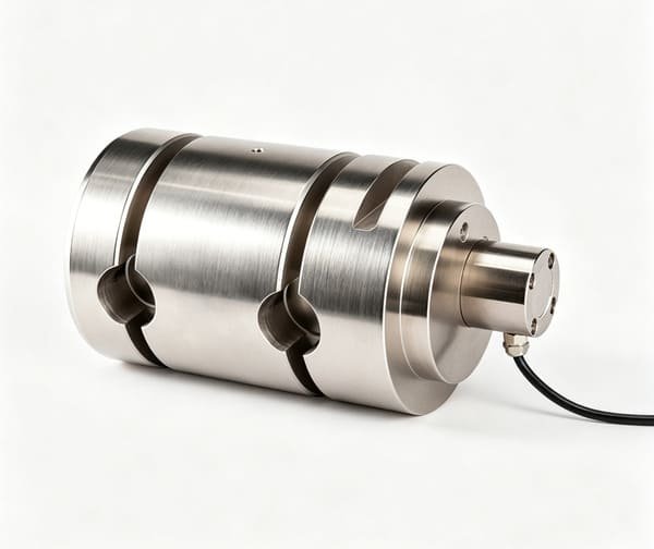
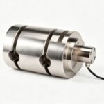
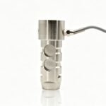
Shaft-pin load cells, also known as load pins, are robust, direct-replacement sensors designed to turn standard mechanical shafts into precise force-measuring devices.
⚙️ Key Features
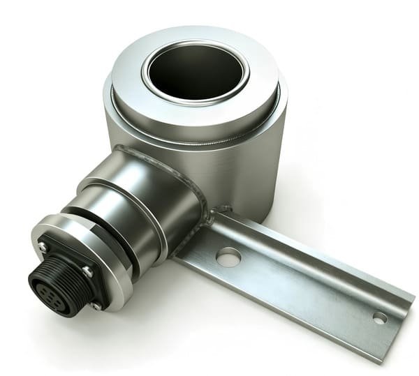
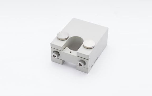
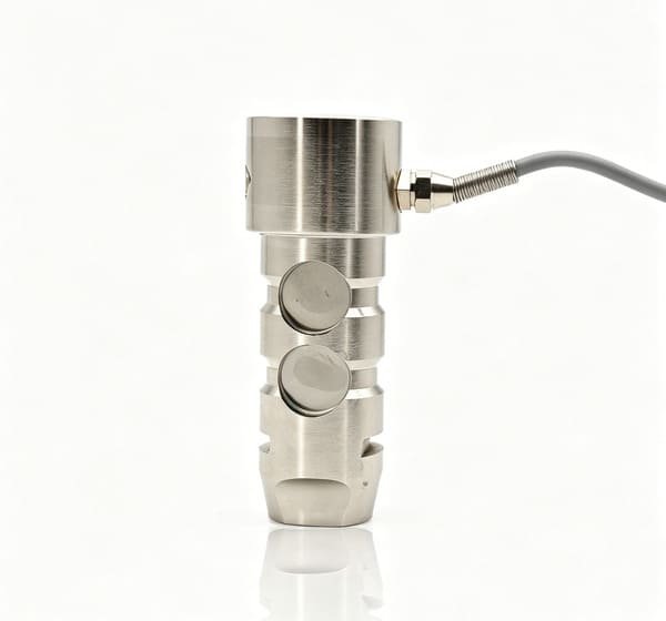
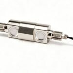
Direct Integration: Designed to directly replace standard pins, shafts, or bolts, they require minimal modifications to your existing machinery.
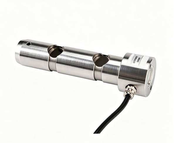
Robust & Compact: Made from high-strength stainless steel with embedded electronics, they withstand harsh environments and fit into tight spaces, protecting sensors from moisture, dust, and corrosive substances.
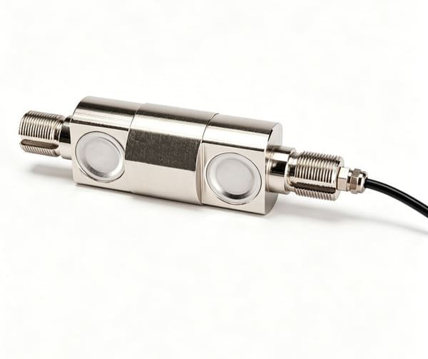
High Accuracy: Modern designs use double-ended shear beam technology for precise measurement (typically within ±0.5% of full scale or better), with excellent resistance to bending and off-center loads.
Customizable: Manufacturers offer custom lengths, diameters, and load capacities, with options for various protection classes (e.g., IP68, submersible up to 16,000 ft), ATEX/IECEx hazardous area certifications, and integrated signal amplifiers for 4-20mA or digital outputs.
📝 Usage & Installation
Proper installation is the most critical factor for optimal performance. Here are the key steps to follow:
Mechanical Installation & Alignment
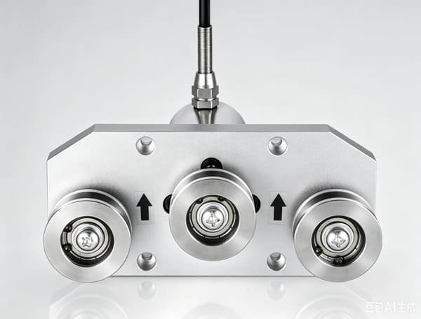
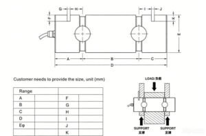
Orientation: Align the load direction marking on the pin with the actual force vector to ensure the strain gauges read correctly.
Fit & Clearance: Maintain a proper fit between the pin and housing, usually an H7/g6 recommendation. Excessive play can cause accuracy loss.
Securing: Use an anti-rotation plate (e.g., a keeper plate) to prevent the pin from rotating, which would damage the internal wiring.
Electrical Connections & Wiring
Standard Connection: With a standard mV/V output (typically ~1-2mV/V), use high-quality shielded cables to prevent noise interference.
Signal Conditioning: Use external amplifiers if your control system (e.g., PLC) cannot read millivolt signals directly. Alternatively, choose an integrated (4-20mA) or digital (RS-485) output version for simpler, longer-distance transmission.
Wiring: The calibration certificate includes a wiring diagram; typically, it uses a four-wire connection: two wires for power excitation and two for the output signal.
System Calibration
Factory Calibration: The pin includes a factory NIST-traceable certificate showing its theoretical output.
In-Situ Calibration (Crucial for Accuracy): This is the most critical step. Perform a system calibration with the pin installed in the final assembly for best accuracy. Apply known test weights or forces to record the actual signal output; this corrects for mechanical influences of your specific equipment.
Calibration Data: Record at least 3-5 test points to verify linearity and repeatability.
Recalibration: Recalibrate annually or after any significant overload event to maintain measurement integrity over time.
🏭 Common Applications
These sensors are ideal for industries requiring real-time load monitoring.
Cranes & Lifting Equipment: Monitors hook loads, winch forces, and provides crane overload protection for tower cranes, mobile cranes, and overhead cranes.
Marine & Offshore: Measures mooring line tensions, anchor forces, and towing loads in challenging offshore environments.
Industrial & Manufacturing: Monitors tension in wire cables, belting, and processes; provides feedback for automated manufacturing and assembly lines.
Heavy Machinery & Construction: Ensures safe operation and load monitoring for excavators, loaders, and other heavy equipment.
Testing & R&D: Validates new product designs and verifies force requirements in research and development settings.
Additional Use Cases: Includes elevators/hoists for weight monitoring, railway couplings for drawbar force monitoring, and aerospace systems for component stress testing.
If you have a particular equipment type or industry in mind, feel free to ask for more specific guidance.
| Range | 50-1000(KN) | Temp.Effect On Load | ±0.05%F.S/10℃ |
| Accuracy | 0.5%F.S | Insulation Resistance | ≥5000MΩ |
| Sensitivity | 1.0-2.0mV/V | Operating Temperature | -20℃-+65℃ |
| Creep | ±0.05%F.S/30min | Excitation Voltage | Suggest 10V DC |
| Zero Output | ±1%F.S | Maximum safe overload | 150%F.S |
| Input Resistance | 750±15Ω | Connection | E+:Red E-:Black S+:Green S-:White |
| Output Resistance | 700±5Ω | ||
| Temp.Effect On Zero | ±0.05%F.S/10℃ |