
Load Cell Junction Box Wiring Diagram & Adjustment Guide (Step-by-Step)
By Robin · Weighing Sensor Export Specialists · Updated 2026 · Reading time: 11 min
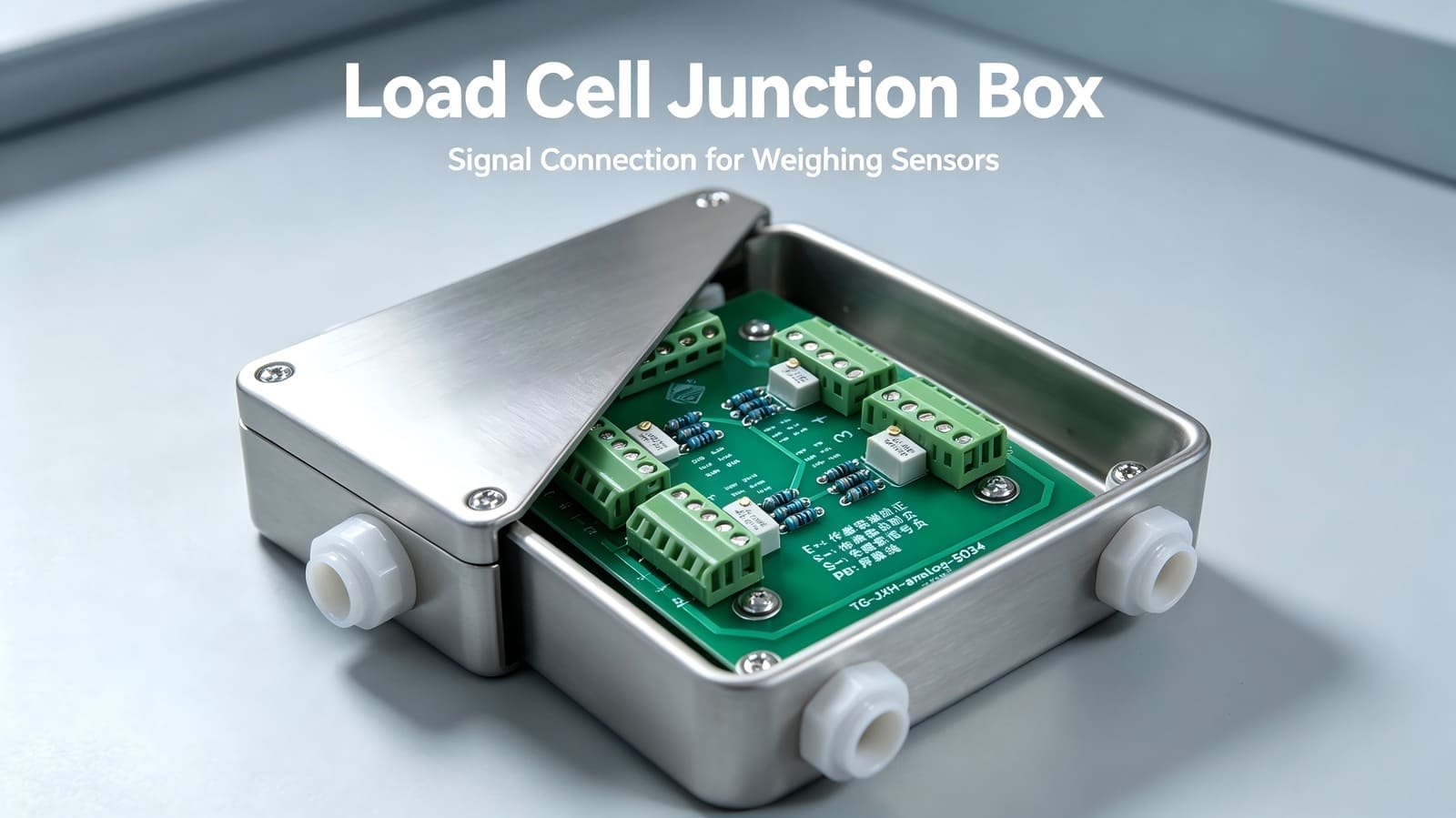
A load cell junction box (also called a summing box or combiner box) is the small
device that lets several load cells share one weighing indicator. This guide explains what it does,
how to read its wiring diagram, how to connect the cables by color, and exactly how to adjust the
corner balance of a multi-sensor scale. It also includes a troubleshooting table and the FAQs buyers
ask most.
1. What is a load cell junction box?
When a weighing system uses two or more load cells (a platform scale, a tank weigher,
a truck scale, a silo, etc.), each sensor leaves the factory with a slightly different output. Even
identical-model cells rarely produce the exact same millivolt signal under the same load. If you simply
parallel-wired them together, the stronger cells would dominate and the scale would read incorrectly at
different positions — a problem known as corner error.
A load cell junction box solves this. It sums the signals of all connected cells into a
single output for the indicator, and it contains a small adjustable resistor (trim potentiometer) on each
channel so you can fine-tune every cell’s contribution until they are balanced.
box required. You need a junction box whenever multiple load cells feed one display/controller.
2. How a junction box works
A junction box performs two jobs:
- Summing (combining) the signals. Each cell’s signal lines (S+ and S−) are tied to a common bus, so the indicator sees the algebraic sum of all cells.
- Corner / angle adjustment. A trim potentiometer on each channel lets you slightly reduce that cell’s effective output. You adjust every cell down to match the weakest one, so all corners give the same reading under the same load.
Without a junction box the system can still “receive a signal,” but the multi-sensor outputs will be
unbalanced and the scale will not weigh accurately across its platform.
3. Types of load cell junction boxes
| Type | Use case | Key feature |
|---|---|---|
| Analog junction box | For analog (mV/V) load cells | Mechanical trim pots; most common and lowest cost |
| Digital junction box | For digital (RS485 / bus) load cells | Adjustment done in software; no manual pots; better long-term stability |
| Explosion-proof junction box | Flammable / explosive environments | Certified enclosures (e.g., Ex d / Ex ia) for hazardous areas |
| Anti-surge junction box | Sites with lightning / power surges | Suppressor components minimize surge current/voltage damage |
Choose the type that matches your load cell signal type first, then the environmental
rating you need (see Section 10).
4. Load cell junction box wiring diagram
Below is a simplified schematic of a typical 4-in-1-out analog junction box. Four load
cells connect on the left; the balanced combined signal exits on the right to the weighing indicator.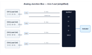
Replace the schematic with a real photo of your product if you sell the box itself. Either way, keep the
labeled terminals visible — readers and buyers look for this first.
5. Terminal block definitions
A standard junction box terminal is marked as follows (some brands use EXC/SIG instead of E/S — they mean the same thing):
| Marking | Full name | Function |
|---|---|---|
| E+ (EXC+) | Excitation power + | Supplies positive drive voltage to the cell |
| E− (EXC−) | Excitation power − | Supplies negative drive voltage to the cell |
| S+ (SIG+) | Signal output + | Positive millivolt signal from the cell |
| S− (SIG−) | Signal output − | Negative millivolt signal from the cell |
| PB / SHLD | Shielded wire / ground | Connects cable shield to the box ground post |
6. Load cell cable color codes
Wire colors are not universal — they vary by manufacturer and country. Always confirm
against the sensor’s datasheet. The two most common conventions are:
| Function | Common A | Common B |
|---|---|---|
| Excitation + (E+) | Red | Red |
| Excitation − (E−) | Black | White |
| Signal + (S+) | Green | Green |
| Signal − (S−) | White | Blue |
| Shield (SHLD) | Bare / metal braid | Bare / metal braid |
the supply voltage (e.g. 5–15 V); S+ to S− reads a few millivolts that rises when you press the cell.
7. Installation
- Fix the junction box in a suitable position on the scale body and open its top cover.
- Plug each load cell cable and the indicator signal cable into the matching terminals, following the diagram above (E+→E+, E−→E−, S+→S+, S−→S−, shield→shield).
- Tighten every cable gland nut. Fill any unused ports with the supplied rubber gasket or sealant so the enclosure stays IP-rated.
- Connect the outer shield of all cables to the box’s grounding post.
- Close and screw down the cover before powering up.
8. Corner adjustment (step-by-step)
Adjustment balances the output of every cell so the same load gives the same reading at every position.
You can only reduce a cell’s output with the trim pot, so you tune every cell down to the
lowest one.
- 1
Map cells to terminals. Label each load cell (No.1–No.4) and note which junction-box terminal (1/2/3/4) it connects to. - 2
Measure each cell under the same load. Put cell No.1 on terminal 1, apply a known pressure/weight, and record the reading. Remove it, then repeat for cells 2, 3 and 4 on their respective terminals. Keep the applied load identical each time. - 3
Balance to the lowest value. Find the smallest recorded number. Rotate each yellow trim potentiometer until every channel reads equal to that lowest value.
90 kg and 100 kg cells down until all four read 80 kg. Never force a pot past its
stop — turn gently.
After adjustment, close the cover and tighten the screws. Re-check the corner test on the assembled scale
to confirm balance.
9. Troubleshooting
| Symptom | Likely cause | What to check / do |
|---|---|---|
| No reading / no signal | Excitation not connected, no power, loose terminal | Verify E+/E− continuity and supply voltage; re-seat terminals; press each one firmly |
| Negative or reversed reading | Signal wires swapped | Swap S+ and S− at the terminal |
| Unstable / drifting display | Poor shielding/grounding, moisture, EMI | Check shield ground; reseal enclosure; route sensor cables away from power lines |
| Different reading at each corner | Unbalanced trim pots or sensor mismatch | Repeat the corner adjustment; confirm all cells are the same model |
| Reading jumps when load moves | Loose mechanical mount or bad connection | Inspect cell mounting; tighten terminals one by one |
| Overload / zero won’t settle | Wrong box type or cell rating | Confirm analog vs digital and cell capacity match the application |
10. How to choose the right junction box
- Channel count: match the number of load cells (commonly 4, 6, 8 or 10 channels).
- Signal type: analog cells → analog box; digital cells → digital box.
- Environment: stainless steel + high IP (IP65/IP67) for washdown or outdoor; explosion-proof for hazardous areas; anti-surge for lightning-prone sites.
- Matching cells: all connected cells should be the same model, with input/output impedance and sensitivity close to each other (aim for error within 0.01%).
- Cable & gland size: confirm the box accepts your cable diameter for a proper seal.
11. Frequently asked questions
What does a load cell junction box do?
It combines the signals of multiple load cells into one output for a single indicator, and lets you trim each cell so the scale weighs evenly at every corner.
Do I need a junction box for a single load cell?
No. One load cell connects directly to the indicator. A junction box is needed only when two or more cells share one display or controller.
Can I wire load cells together without a junction box?
Technically you can parallel the signals, but without the per-channel trim resistors the cells will be unbalanced and corner errors will be large. A junction box is the correct, repeatable solution.
How many load cells can one junction box handle?
It depends on the box. Standard off-the-shelf boxes have 4, 6, 8 or 10 channels; custom boxes can handle more. Match the channel count to your scale.
How do I know which wire is excitation vs signal?
Check the cell’s datasheet and color code. If unsure, use a multimeter: excitation reads supply voltage (V), signal reads a few mV that increases under load.
Analog or digital junction box — which is better?
Analog boxes are simple and cheap with manual trim pots. Digital boxes adjust in software, drift less over time, and suit systems that need remote calibration or diagnostics.
Why are my corner readings different even after adjustment?
Usually unbalanced trim pots, mismatched cells, a loose terminal, or a mechanical mounting issue. Repeat the corner test and confirm all cells are the same model and properly seated.
12. Conclusion
A load cell junction box is a small but critical part of any multi-sensor scale. Read the terminal labels
(E+/E−/S+/S−/shield), match the cable colors to the datasheet, seal the enclosure for the environment, and
balance the corners by trimming every cell down to the lowest one. Get those steps right and your scale
will weigh accurately across its whole platform.
Need load cells or junction boxes for your project?
We supply analog and digital load cells, summing/junction boxes, explosion-proof and anti-surge
versions, and full weighing kits for export. Browse our load cell catalog or
contact our engineering team for help sizing the right box and cells for your scale.