
Everything you need to know about load cells (weight sensors) — from strain gauge fundamentals and Wheatstone bridge circuits to classification, technical parameters, selection rules, calibration, and maintenance.
✏️ Updated: January 15, 2025
⏱️ 25 min read
Load cells are the unseen backbone of modern weighing and force measurement systems. From the digital scale at your doctor’s office to massive truck weigh stations on the highway, from precision laboratory balances to industrial batching plants — load cells silently convert physical force into reliable electrical signals that drive decisions worth millions of dollars every day.
If you are an engineer designing a weighing system, a procurement manager sourcing sensors for an industrial project, or a trade professional evaluating load cell suppliers, this guide will give you a thorough understanding of how load cells work, how to choose the right one, and how to get the best performance from your weighing equipment.
This guide covers load cell fundamentals, the physics behind strain gauge technology, all major classification systems, critical technical parameters explained in plain language, a practical selection methodology, IP protection ratings, calibration best practices, maintenance tips, industry certifications, and answers to the most common questions.
1. What Is a Load Cell?
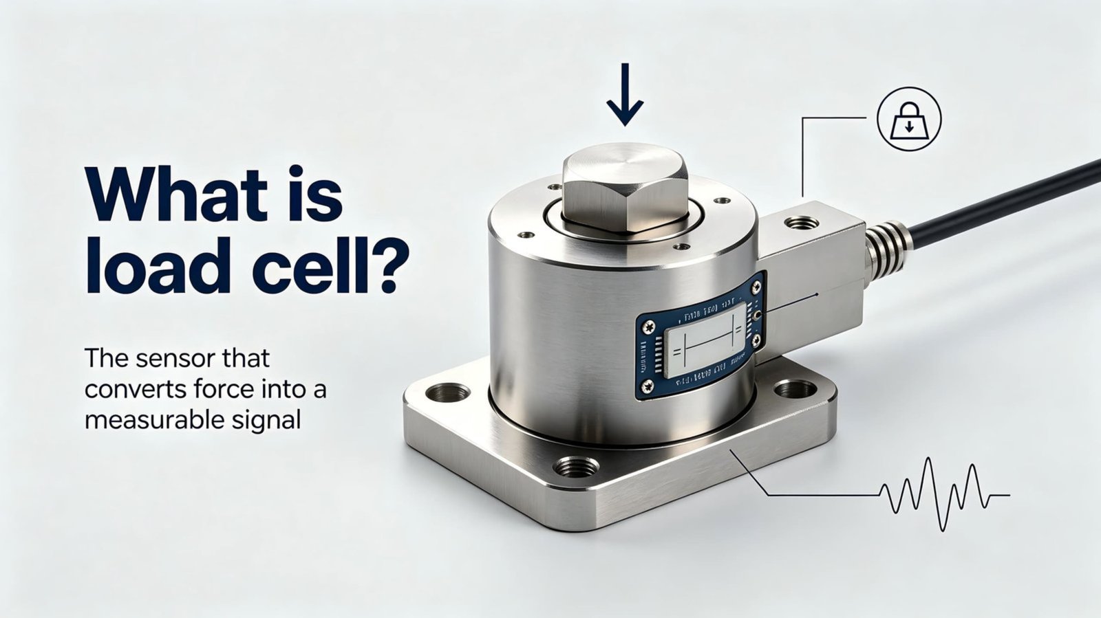
A load cell (also called a weight sensor or force transducer) is a device that converts the force of gravity acting on an object into a measurable electrical signal proportional to the applied weight or force. In simpler terms, it is the component inside a scale that actually “feels” the weight and turns that physical force into numbers you can read on a display.
Based on the conversion method, load cells are generally divided into eight categories:
- Photoelectric type
- Hydraulic type
- Electromagnetic force type
- Capacitance type
- Magnetic pole change type
- Vibration type
- Gyroscope type
- Resistance strain gauge type — the most widely used
Over 90% of load cells in industrial use today are the resistance strain gauge type. They offer an excellent balance of accuracy, reliability, cost-effectiveness, and versatility across a wide range of capacities and environments. This guide focuses primarily on this type.
2. Working Principle of a Load Cell
2.1 Definition
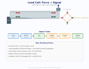
A load cell is fundamentally a transducer that converts weight or force into a measurable electrical output. The process works as follows:
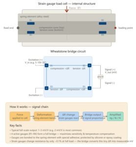
Force/Weight Applied → Elastomer Deformation → Strain Gauge Resistance Change → Wheatstone Bridge Voltage Output
2.2 Core Components
A strain gauge load cell consists of three essential parts:
| Component | Material | Function |
|---|---|---|
| Sensitive Element | Resistance strain gauge | Detects mechanical deformation and converts it to resistance change |
| Sensing Element | Metallic elastomer (stainless steel, alloy steel, or aluminum alloy) | Transfers the applied force to the strain gauge in a controlled manner |
| Measuring Circuit | Wheatstone bridge | Converts resistance change into a proportional voltage signal |
Common resistance values for strain gauges are 350Ω, 700Ω, and 1000Ω. Common elastomer materials include:
- Stainless steel (e.g., 17-4PH) — for corrosive environments
- Alloy steel (e.g., 40Cr) — for general industrial use
- Aluminum alloy (e.g., LY12) — for small-capacity and commercial applications
3. Understanding Resistance Strain Gauges
3.1 What Is a Resistance Strain Gauge?
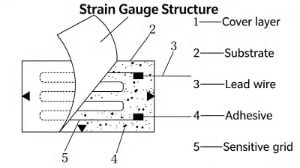
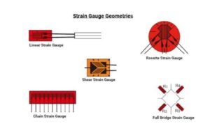
A resistance strain gauge is constructed by arranging a fine resistance wire in a grid pattern and bonding it to an insulating substrate approximately 15–16μm thick. Lead wires are welded to both ends of the resistance wire, and a protective covering layer is applied on top. When bonded to the measured object, it forms a strain sensor capable of detecting minute surface deformations.
3.2 Working Principle: The Strain Effect
The conversion principle is based on the resistance-strain effect of metallic conductors. When a metal wire is stretched, its resistance increases; when compressed, its resistance decreases. This is a physical phenomenon where the resistance value of a metal conductor changes in proportion to its mechanical deformation (elongation or shortening).
The relationship is governed by the fundamental resistance formula:
When the wire is stretched: L increases → S decreases → R increases. When compressed: L decreases → S increases → R decreases. This proportional change in resistance is the foundation of strain gauge measurement.
3.3 Classification of Metal Resistance Strain Gauges
Metal resistance strain gauges are classified into three types:
| Type | Construction | Characteristics |
|---|---|---|
| Wire Type | Fine resistance wire wound in a grid pattern | Earliest design; lower accuracy; rarely used in modern load cells |
| Foil Type | Thin metal foil etched into a grid pattern on a substrate | Most common; excellent heat dissipation; high linearity; good stability |
| Film Type | Thin film deposited directly on the elastomer via vacuum deposition | Highest performance; no adhesive layer; excellent long-term stability |
3.4 Application Methods
There are two ways to use resistance strain gauges:
- Direct bonding: The strain gauge is bonded directly onto the measured object to measure strain or stress at that specific location.
- Elastomer integration: The strain gauge is bonded to an elastic element, and together they form a complete strain sensor — this is how load cells are built.
3.5 Strain Gauge Bonding Technology
The quality of strain gauge bonding directly determines the accuracy and long-term stability of a load cell. Key bonding precautions include:
- Ensure the bonding surface is clean, flat, and free of oxide layers
- Use appropriate adhesive (cyanoacrylate for general use, epoxy for high-temperature)
- Apply uniform pressure during curing to eliminate air bubbles
- After bonding, weld the lead wires and fix them securely with insulation to prevent short circuits between the strain gauge terminals and the workpiece
- Connect strain gauges using enameled wire or flexible conductors to form a Wheatstone bridge
- Perform moisture-proof sealing after bonding is complete
4. Classification of Load Cells
Load cells can be classified from multiple perspectives. Understanding these classifications is essential for selecting the right sensor for your application.
4.1 By Force Mode
| Type | Description | Typical Applications |
|---|---|---|
| Compression type | Measures compressive force only | Truck scales, silo weighing, platform scales |
| Tension type | Measures tensile (pulling) force only | Crane scales, hanging scales, tensile testing |
| Tension & compression type | Measures both push and pull forces | Material testing machines, universal testing |
| Single-ended shear beam | Measures shear force at one end | Platform scales, floor scales, tank weighing |
4.2 By Elastomer Material
| Material | Grade | Best For |
|---|---|---|
| Stainless Steel | 17-4PH | Food, chemical, pharmaceutical, and other corrosive environments |
| Alloy Steel | 40Cr | General industrial use in non-corrosive environments |
| Aluminum Alloy | LY12 | Small-capacity, commercial weighing applications |
4.3 By Output Signal Type
| Type | Output Signal | Advantages |
|---|---|---|
| Analog load cell | Voltage or current (mV/V) | Simple structure, lower cost, widely compatible |
| Digital load cell | Digital signal (RS485, RS422, CAN bus) | Strong anti-interference, long-distance transmission, built-in diagnostics |
4.4 By Operating Temperature
| Category | Temperature Range | Applications |
|---|---|---|
| Normal temperature | -10°C to +55°C | Conventional indoor and outdoor environments |
| High temperature | Up to +200°C or higher | Metallurgy, nuclear power, foundries |
| Low temperature | Below -30°C | Freezing test, cold storage, polar operations |
4.5 By Accuracy Grade
According to comprehensive accuracy, load cells are divided into four levels:
| Grade | Accuracy Level | Typical Use Case |
|---|---|---|
| A | Highest precision | Laboratory balances, metrology standards |
| B | High precision | Trade weighing, batching systems |
| C | Medium precision | Industrial process control |
| D | General purpose | Crude weighing, overload alarms |
4.6 By Structure
The structural design of a load cell determines how it handles force, its mounting method, and its suitability for different applications:
- Column type — High capacity, robust; used in truck scales and heavy industrial weighing
- Spoke type — Low profile, high rigidity; ideal for press-fit force measurement
- Single point type — Off-center loading capability; used in bench scales and retail scales
- Micro type — Compact size; for small-capacity precision measurement
- Shear beam type — Excellent lateral load resistance; widely used in platform and floor scales
- Bridge type (bending beam) — Simple structure; for medium-capacity applications
- Shaft pin type — Integrated into pins or axles; for crane scales and hoist monitoring
- S-type — Versatile tension/compression; for hanging scales and force testing
- Canister/Compression type — Rugged cylindrical design; for heavy-duty compression weighing
5. Applications of Load Cells
Load cells are used across virtually every industry that involves weighing, force measurement, or process control:
5.1 Electronic Weighing Equipment
- Electronic truck scales and railway track scales
- Electronic platform scales and bench scales
- Electronic forklift scales and hook scales
- Electronic pricing scales (retail)
- Dynamic axle load measurement systems
- Automatic weighing and packaging machines
5.2 Industrial Process Control
- Weighing modules for hopper scales, batching scales, and canning scales
- Online control metering and dosing systems
- Material batching and mixing control
- Safety overload alarms and overload protectors
- Weight limiters for cranes and lifting equipment
5.3 Material Testing & Research
- Universal material testing machines
- Tensile, compression, and fatigue testing equipment
- Laboratory precision balances
Load cells are increasingly used in IoT smart agriculture (livestock weight monitoring), logistics automation (conveyor sorting), medical devices (patient beds, infusion pumps), aerospace (thrust measurement), and renewable energy (wind turbine load monitoring).
6. Load Cell Manufacturing Process
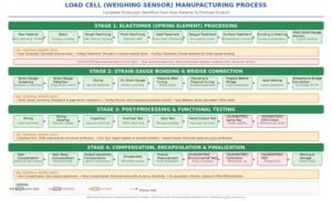
The production of a strain gauge load cell involves two main phases: elastomer machining and strain gauge bonding and compensation.
Phase 1: Elastomer Processing
- Material selection — Choose appropriate steel or aluminum alloy based on capacity and environment
- Rough machining — CNC turning and milling to create the basic elastomer shape
- Heat treatment — Quenching and tempering to achieve optimal hardness, strength, and elastic properties
- Precision machining — Fine grinding to achieve dimensional accuracy and surface finish requirements
- Surface treatment — Nickel plating, passivation, or anodizing for corrosion protection
Phase 2: Strain Gauge Bonding & Compensation
- Surface preparation — Clean and polish the bonding area
- Strain gauge bonding — Apply adhesive and bond strain gauges under controlled pressure and temperature
- Curing — Allow adhesive to fully cure per manufacturer specifications
- Wiring — Connect strain gauges into a Wheatstone bridge configuration
- Compensation — Install compensation resistors for zero balance, temperature, linearity, and sensitivity
- Sealing — Apply protective sealing (glue, potting, or welding) per IP rating requirement
- Calibration & testing — Perform full-range loading tests to verify accuracy, repeatability, and creep
7. Load Cell Compensation Technology
Due to manufacturing tolerances and material properties, raw load cells require electrical compensation to achieve the accuracy and stability needed for practical use. Compensation is what separates a quality load cell from a crude force sensor.
7.1 Common Compensation Items
| Item | Purpose |
|---|---|
| Zero unbalanced output adjustment | Adjust the no-load output to within specification |
| Zero temperature compensation | Compensate for zero drift caused by ambient temperature changes |
| Elastic modulus (sensitivity temperature) compensation | Compensate for sensitivity changes due to temperature |
| Nonlinear compensation | Correct the natural nonlinearity of the sensor’s response curve |
| Sensitivity compensation | Normalize full-load output for interchangeability |
| Output resistance adjustment | Match output impedance for multi-sensor systems |
7.2 Compensation Circuit Components
| Symbol | Name | Function | Material |
|---|---|---|---|
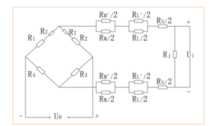
| R1–R4 | Wheatstone bridge strain gauges | Directly sense elastomer strain (typically 350Ω, 700Ω, or 1000Ω) | Constantan or Karma alloy |
| RZ | Zero compensation resistor | Adjust no-load output to required range | Manganin wire (temperature-insensitive) |
| RT | Zero temperature compensation resistor | Compensate for zero drift under temperature changes | Nickel resistor (temperature-sensitive) |
| RM | Elastic modulus compensation resistor | Compensate for sensitivity changes with temperature | Nickel wire (temperature-sensitive) |
| RL | Linear compensation resistor | Adjust natural nonlinearity for linear response | Semiconductor strain gauge |
| RS | Sensitivity compensation resistor | Adjust full-load output for interchangeability | Copper wire (temperature-insensitive) |
| RJ | Output resistance adjusting resistor | Match output impedance for multi-sensor parallel use | Metal film resistor |
7.3 Why Each Compensation Matters
Zero Temperature Compensation (RT)
When a load cell operates outdoors or in environments with significant temperature fluctuations (e.g., morning vs. noon), its internal resistance changes with temperature, causing zero drift. This makes the display unstable or causes measurement deviation. The RT nickel resistor, which is sensitive to temperature, counteracts this drift automatically.
Zero Compensation (RZ)
If the sensor’s zero output exceeds a certain range, the connected display instrument may show abnormal readings (no signal, overflow, or alarm). The RZ manganin wire resistor adjusts the no-load output back to the required range. Manganin is used because it is insensitive to temperature, ensuring the adjustment remains stable.
Output Temperature Compensation (RM)
Elastomer metals have an elastic modulus (E) that changes slightly with temperature. Under the same load, readings in hot weather will be greater than in cold weather — an unacceptable deviation for precision measurement. The RM nickel wire resistor compensates for this sensitivity-to-temperature effect.
Linear Compensation (RL)
Column-type sensors, in particular, have inherently poor linearity. The RL semiconductor strain gauge corrects this nonlinearity, enabling the sensor to meet high-precision measurement requirements.
Sensitivity Compensation (RS)
Consider a table with four legs of unequal length — it wobbles. Similarly, in a multi-sensor weighing system, if the sensitivities of individual sensors are not identical, the scale will produce different readings depending on where the object is placed. Only one reading can be correct; the rest are wrong. This violates the fundamental principle of “fair dealing” in weighing. The RS copper wire resistor normalizes each sensor’s full-load output so they are interchangeable.
8. Key Technical Parameters Explained
Understanding technical parameters is critical for evaluating and comparing load cells. Here we explain each parameter in clear, practical terms.
8.1 Rated Load (Capacity)
The maximum weight that the load cell is designed to measure. This is the fundamental specification for any load cell. Always select a capacity that exceeds your maximum expected load (including tare weight) with an appropriate safety margin.
8.2 Rated Output (Sensitivity)
The difference between the sensor’s output signal at rated load and at zero load. Because the output signal depends on the excitation voltage, the rated output is expressed in mV/V and is also called sensitivity.
A load cell with a rated load of 100 kg and an excitation voltage of 10 V outputs 0 mV at zero load and 20 mV at 100 kg. The rated output (sensitivity) = (20 − 0) / 10 = 2 mV/V.
When multiple sensors are used in parallel (e.g., in a floor scale), all sensors must have the same sensitivity and capacity. If they differ, the scale will show different weights depending on where the object is placed. When replacing a damaged sensor, find one with the same sensitivity and rated capacity — other parameters are less critical. Sensors from different manufacturers can be used together as long as these two parameters match.
8.3 Sensitivity Tolerance Range
The difference between the actual stable output and the nominal rated output, expressed as a percentage of the nominal rated output. For example, if the actual output is 2.002 mV/V and the nominal is 2.000 mV/V, the sensitivity tolerance is: (2.002 − 2.000) / 2.000 × 100% = 0.1%.
8.4 Non-Linearity Error
The maximum deviation between the straight line connecting the zero-load output and the rated-load output, and the actual measured curve obtained by incrementally increasing the load — expressed as a percentage of the rated output. A lower non-linearity error means the sensor’s response is more proportional across its entire range.
8.5 Hysteresis Error
Load is gradually increased from zero to rated load, then gradually decreased. At the same load point, the output during loading differs from the output during unloading. The maximum difference at any load point, as a percentage of the rated output, is the hysteresis error.
8.6 Repeatability Error
Under the same environmental conditions, the sensor is repeatedly loaded to rated load and unloaded. The maximum difference between output values at the same load point across multiple loading cycles, expressed as a percentage of the rated output, is the repeatability error. This is one of the most important indicators of sensor quality.
8.7 Creep
When a constant load (typically the rated load) is applied and all other test conditions remain unchanged, the change in the sensor’s output over time — expressed as a percentage of the rated output. Creep can be positive (output increases over time) or negative (output decreases over time).
8.8 Zero Balance (Zero Output)
The sensor’s output at the recommended excitation voltage with no load applied, expressed as a percentage of the rated output. A well-compensated load cell should have a very low zero balance.
8.9 Insulation Resistance
The DC impedance between the sensor’s circuit and its elastomer (metal body). This is tested after strain gauge bonding and bridge assembly. Note that the measured value depends on the test voltage: lower test voltages yield higher resistance readings, and vice versa. Always specify the test voltage when stating insulation resistance.
- Steel elastomer sensors: typically > 5,000 MΩ (at 50 VDC)
- Aluminum elastomer sensors: typically > 2,000 MΩ (at 50 VDC)
Example specification: R = 20,000 MΩ (15 VDC)
8.10 Input Resistance
The impedance measured at the excitation (power) input terminals when the signal output is open and the sensor is unloaded.
8.11 Output Resistance
The impedance measured at the signal output terminals when the excitation input is short-circuited and the sensor is unloaded.
8.12 Temperature Compensation Range
The temperature range within which the rated output and zero balance of the sensor have been strictly compensated and will not exceed specified limits.
8.13 Temperature Effect on Zero
The change in zero output caused by ambient temperature change, typically expressed as the percentage change in zero output per 10°C temperature change relative to the rated output.
8.14 Temperature Effect on Rated Output
The change in rated output due to ambient temperature change, typically expressed as the percentage change per 10°C.
8.15 Operating Temperature Range
The temperature range within which the sensor can operate without permanent harmful changes to any performance parameter.
9. Load Cell Selection Guide
Choosing the right load cell requires a thorough understanding of your installation requirements, operating environment, and accuracy needs. Here is a practical selection methodology covering structure, capacity, and accuracy.
9.1 Choosing the Right Structure
The structural form of the load cell depends on the weighing device design and environmental conditions:
- Low-profile weighing instruments: Choose shear beam, spoke type, torsion ring, or round plate type load cells.
- No height restriction: Column or double shear beam type load cells are suitable.
- Humid or dusty environments: Select a well-sealed load cell — welded seal with IP67 or IP68 rating is recommended.
- Explosion hazard areas: Use intrinsically safe (Ex ia) load cells.
- Elevated mounting (overhead): Safety and overload protection must be considered.
- High-temperature environments: Choose load cells with water-cooling jackets.
When selecting a structure, also consider maintenance accessibility and replacement cost. If a weighing system fails, can you quickly obtain replacement parts? If not, the structural choice may be inappropriate.
9.2 Choosing the Right Capacity (Weight Range)
The closer the actual weighing value is to the sensor’s rated capacity, the higher the weighing accuracy. However, in practice, factors like tare weight, vibration, impact, and load offset must be accounted for.
| System Type | Selection Rule |
|---|---|
| Static weighing system (single or multi-sensor) |
Fixed load (platform, container) + variable load (weighed material) ≤ rated capacity × 50–70% |
| Dynamic weighing system (single or multi-sensor) |
Fixed load + variable load ≤ rated capacity × number of sensors × 30–50% |
- Choose rated capacities from the manufacturer’s standard product series whenever possible. Non-standard products are more expensive and harder to replace.
- Never mix sensors with different rated capacities in the same weighing system — the system will not function correctly.
- “Variable load” refers to the actual load on the sensor. If there is a lever or attenuation mechanism between the weighing platform and the sensor, account for this multiplication/reduction factor.
9.3 Choosing the Right Accuracy
The accuracy grade should meet — but not excessively exceed — the requirements of your weighing system. If a 2,500-division sensor is sufficient, do not choose a 3,000-division sensor unnecessarily.
When multiple sensors of the same form and capacity are used in parallel, the comprehensive error is:
An electronic weighing system consists of three parts: load cell, weighing display, and mechanical structure. When the system tolerance is 1, the load cell’s comprehensive error is typically only 0.7 of the proportional component. Combined with the formula above, this makes it straightforward to determine the required sensor accuracy.
10. Protection Grade (IP Ratings) Explained
IP (International Protection) is a standard that classifies the degree of protection provided by electrical enclosures against dust and moisture. The rating consists of two numbers: the first indicates dust and foreign object protection, the second indicates moisture and waterproof protection. Higher numbers mean better protection.
| Rating | Protection Level | Test Conditions | Load Cell Construction |
|---|---|---|---|
| IP65 | Splash-proof | Water from a 6.3mm nozzle at 30 kPa (0.3 bar), 11.9–13.2 L/min, from 2.5–3m distance, 1 min/m² (min. 3 min total) | Elastomer surface sealed with glue |
| IP66 | Strong water jet protection | Water from a 12.5mm nozzle at 100 kPa (1 bar), 95–105 L/min, from 2.5–3m distance, 1 min/m² (min. 3 min total) | Cover plate sealed with glue + internal glue protection |
| IP67 | Temporary immersion protection | Immersion: water surface 150mm above sensor top, 1m above bottom, temp. difference ≤ 5K, min. 30 min | Welded cover plate (or bellows) + internal glue protection; oil-proof, waterproof, corrosion-resistant |
| IP68 | Continuous submersion protection | Per manufacturer-user agreement; conditions must be at least as severe as IP67 | Special underwater-rated construction with fully welded sealing |
- Indoor, clean environment: IP65 is sufficient
- Outdoor, occasional rain: IP66 recommended
- Washdown / food processing: IP67 minimum (IP68 for continuous wet)
- Underwater / submerged: IP68 required
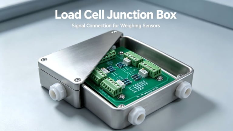
11. Load Cell Junction Box
When two or more load cells are combined in a weighing system, each sensor’s output signal will differ slightly due to manufacturing tolerances. To achieve consistent output across all sensors, a <strong;junction box (also called a summing box or <strong;junction box with trimmer) is used to balance the signals.
Primary Functions
- Signal summing: Combines the output signals from multiple sensors into a single signal for the display or controller.
- Corner adjustment (angle error correction): Adjustable resistors in the junction box allow fine-tuning of each sensor’s contribution, ensuring that the scale reads the same weight regardless of where the load is placed on the platform.
In a multi-sensor system, the system can receive signals without a junction box. However, because each sensor’s output may differ slightly, using a junction box to adjust and balance the signals is strongly recommended to ensure weighing accuracy. Without it, the system may show different readings at different positions on the weighing platform.
12. Analog vs. Digital Load Cells: Which Should You Choose?
One of the most common decisions when sourcing load cells is whether to choose analog or digital output. Each has distinct advantages:
| Feature | Analog Load Cell | Digital Load Cell |
|---|---|---|
| Output Signal | mV/V (analog voltage) | RS485, RS422, CAN bus (digital) |
| Signal Transmission Distance | Limited (typically < 30m without amplifier) | Long distance (up to 1,000m+ with RS485) |
| Anti-Interference | Susceptible to EMI/RFI; requires shielded cable | Strong immunity; digital error checking |
| Built-in Diagnostics | No self-diagnostics | Self-diagnosis, fault reporting, status monitoring |
| Individual Addressing | Not possible (all sensors share one signal) | Each sensor has unique address; individually readable |
| Cost | Lower | Higher (built-in electronics) |
| Calibration | System-level calibration required | Each sensor pre-calibrated; digital compensation |
| Best For | Simple systems, short distances, budget projects | Industrial networks, long-distance, harsh environments, smart systems |
13. Load Cell Calibration Guide
Calibration ensures your load cell maintains measurement accuracy over time. Here is a practical guide to calibration best practices.
13.1 When to Calibrate
- Initial installation: Always calibrate after installing a new load cell or system
- Routine schedule: Every 6–12 months for industrial applications; quarterly for high-precision use
- After events: Mechanical shock, overload, extreme temperature exposure, or any repair
- Legal-for-trade: Follow OIML R76 or NTEP requirements for recertification intervals
13.2 Calibration Methods
| Method | Description | Best For |
|---|---|---|
| Dead weight calibration | Apply certified test weights directly to the sensor — the most accurate method | Laboratory, trade certification, high-precision systems |
| Substitution method | Use known weights to establish reference points, then substitute with other materials | Large-capacity systems where full dead weights are impractical |
| Standard sensor comparison | Compare readings against a calibrated reference sensor | In-line verification, field testing |
| Electronic calibration | Use a calibrated signal generator to simulate sensor output | Quick checks, display/indicator verification |
13.3 Calibration Steps (General)
- Warm up the system for 15–30 minutes to stabilize electronics
- Ensure the load cell and platform are clean and free of debris
- Record the zero-load reading (zero point)
- Apply known test weights incrementally (at least 5 points: 0%, 25%, 50%, 75%, 100%)
- Record the output at each point and verify linearity
- Remove weights and verify return to zero (check for hysteresis)
- Adjust calibration parameters in the indicator/display as needed
- Document results with date, temperature, and technician initials
14. Maintenance & Troubleshooting
Proper maintenance extends the life of your load cells and ensures consistent accuracy. Here are the most common issues and how to address them.
14.1 Common Faults and Solutions
| Symptom | Possible Cause | Solution |
|---|---|---|
| Display shows zero / no signal | Broken cable, disconnected wire, excitation voltage missing | Check cable continuity; verify power supply; inspect junction box connections |
| Readings drift or fluctuate | Moisture ingress, loose connection, EMI interference, ground loop | Check sealing (IP rating); tighten connections; use shielded cable; eliminate ground loops |
| Overload error | Load exceeds rated capacity; elastomer permanently deformed | Reduce load; if permanently damaged, replace sensor; add overload protection |
| Inconsistent readings at different positions | Sensor sensitivity mismatch; corner adjustment needed | Adjust junction box potentiometers; verify all sensors have same sensitivity |
| Zero drift after temperature change | Inadequate temperature compensation; poor installation (thermal expansion) | Verify compensation quality; ensure mechanical isolation from thermal expansion |
| Readings unstable under vibration | Vibration transmitted to sensor; inadequate damping | Add vibration isolation mounts; use higher sampling rate; implement digital filtering |
14.2 Preventive Maintenance Checklist
- Monthly: Visually inspect cables, connectors, and junction boxes for damage or corrosion
- Quarterly: Clean the load cell and surrounding area; check for mechanical obstructions
- Semi-annually: Perform a calibration check with known weights; verify zero stability
- Annually: Full calibration; inspect mounting hardware for tightness; check environmental seals
- As needed: After any overload event, impact, extreme weather, or system modification
- Do not weld near the load cell without disconnecting it — welding currents can destroy strain gauges
- Do not lift or move equipment by the load cell cables
- Do not exceed the rated capacity, even temporarily, without overload protection
- Do not use load cells in environments exceeding their rated temperature range
15. Industry Certifications & Standards
When sourcing load cells for commercial, industrial, or regulated applications, certifications ensure the product meets internationally recognized standards for accuracy, safety, and quality.
| Certification | Issuing Body | Scope | Why It Matters |
|---|---|---|---|
| OIML R60 | International Organization of Legal Metrology | Metrological regulation for load cells | Required for legal-for-trade weighing in many countries; classifies accuracy (A–D) |
| OIML R76 | International Organization of Legal Metrology | Non-automatic weighing instruments | Defines requirements for complete scale systems using load cells |
| NTEP (NCWM) | National Conference on Weights and Measures (USA) | Legal-for-trade weighing in the United States | Required for commercial weighing applications in the US market |
| ATEX / IECEx | EU / IEC | Explosive atmosphere equipment | Mandatory for load cells used in hazardous (Ex) environments |
| CE / RoHS | European Union | Product safety and materials compliance | Required for sale in the EU market |
| ISO 9001 | International Organization for Standardization | Quality management system | Ensures consistent manufacturing quality and process control |
| NTEP CC | NCWM (USA) | Certificate of Conformance for weighing devices | Specific certification that a load cell model is approved for trade use in the US |
Conclusion
Load cells are precision instruments that form the heart of every modern weighing and force measurement system. Understanding their working principles, classification, technical parameters, and selection criteria empowers you to make informed decisions — whether you are designing a new system, troubleshooting an existing one, or sourcing sensors for international trade.
Key takeaways from this guide:
- The resistance strain gauge principle dominates the industry due to its balance of accuracy, cost, and versatility.
- Proper capacity selection (50–70% for static, 30–50% for dynamic) is critical for accuracy and longevity.
- When using multiple sensors in parallel, matched sensitivity and capacity are non-negotiable.
- IP rating selection should match the worst-case environmental conditions, not just the average.
- Regular calibration and maintenance prevent costly errors and extend equipment life.
- Always verify industry certifications (OIML, NTEP, ATEX) match your application’s regulatory requirements.
By applying the knowledge in this guide, you can confidently select, install, calibrate, and maintain load cells for any application — from a small retail scale to a massive industrial weighing system.
Frequently Asked Questions
What is a load cell and how does it work?
A load cell is a transducer that converts force or weight into a measurable electrical signal. The most common type uses resistance strain gauges bonded to a metallic elastomer. When force is applied, the elastomer deforms slightly, causing the strain gauges to stretch or compress, which changes their electrical resistance. This resistance change is converted into a voltage signal via a Wheatstone bridge circuit.
What are the different types of load cells?
Load cells are classified by structure (column, shear beam, single point, S-type, spoke type, canister), by force mode (compression, tension, tension/compression), by material (stainless steel, alloy steel, aluminum), by output signal (analog or digital), by temperature range (normal, high, low), and by accuracy grade (A, B, C, D).
How do I choose the right load cell for my application?
Consider the weighing device structure, environmental conditions (moisture, dust, temperature, explosion risk), required accuracy, and capacity range. For static systems, the total load should not exceed 50–70% of the rated capacity. For dynamic systems, keep it within 30–50%. Always match sensitivity and capacity when using multiple sensors in parallel.
What is the difference between analog and digital load cells?
Analog load cells output continuous voltage or current signals (typically mV/V), requiring an external amplifier and A/D converter. Digital load cells have built-in electronics that output digital signals (RS485, RS422, CAN bus), offering better noise immunity, longer transmission distances, and easier integration with PLCs and industrial networks.
What IP rating do I need for a load cell?
IP65 is splash-proof (glue-sealed elastomer), suitable for indoor use. IP66 protects against strong water jets (glue-sealed cover plate). IP67 protects against temporary immersion (welded seal), suitable for outdoor and washdown environments. IP68 allows continuous submersion, for underwater or permanently wet applications.
How often should a load cell be calibrated?
For industrial applications, calibration is recommended every 6–12 months. For legal-for-trade weighing, follow OIML or NTEP requirements. High-precision laboratory applications may require quarterly calibration. Always recalibrate after mechanical shock, overload events, extreme temperature exposure, or any repair.
What is sensitivity (rated output) in a load cell?
Sensitivity, also called rated output, is the difference between the sensor’s output signal under rated load and zero load, expressed in mV/V. For example, if a 100 kg load cell outputs 0 mV at zero load and 20 mV at 100 kg with 10V excitation, the sensitivity is (20−0)/10 = 2 mV/V. When using multiple sensors in parallel, all must have the same sensitivity.
Can I use load cells from different manufacturers together?
Yes, as long as the sensors have the same rated capacity and sensitivity (mV/V). These two parameters are the most critical for multi-sensor parallel operation. Other parameters like input/output resistance can vary slightly without major impact. However, for best performance, using identical sensors from the same manufacturer is always recommended.
Need the Right Load Cell for Your Project?
Our team of load cell specialists can help you select the perfect sensor for your application — from capacity and accuracy to IP rating and certifications. Get expert advice and competitive pricing on quality load cells.
Weight Sensor
Strain Gauge
Force Measurement
Weighing Technology
Industrial Sensors
Calibration
About the Author: This article was written by the technical team at Vektorforce, a leading supplier of load cells and weighing solutions with over 20 years of experience in the industry. We specialize in load cell manufacturing, customization, and export for global markets.
Have questions about this article or need help selecting a load cell? Contact our team — we’re happy to help.