
Sep 14, 2026
10 min read
Retrofit Weighing · Structural Monitoring
Micro Strain Sensor on a Cement Silo: Weighing 200-Tonne Silos Without Cutting a Single Leg
An eight-silo retrofit in Vietnam taught me what brochures never mention about weldable strain sensors: hot-work permits that stall week one, a sun-side zero drift worth 4 tonnes, and how to calibrate a silo that was never a scale. Here is the whole engineering story.

In this article
- Why cement silo inventory is harder than it looks
- Three retrofit options compared
- The project: eight silos, zero shutdown days
- How a weldable micro strain sensor turns a leg into a scale
- Three field problems and how we fixed them
- The calibration protocol, summarized
- Where the weighing core ends
- What I would specify today
- FAQ
1. Why Cement Silo Inventory Is Harder Than It Looks
Two years ago, a procurement manager at a ready-mix concrete plant in Vietnam emailed me a question that sounded simple: “Michael, can we know how many tonnes of cement are left in each of our silos, without touching the silo itself?”
His plant ran eight 200-tonne cement silos. Every morning, delivery trucks were dispatched on guesswork — sometimes a silo ran dry mid-pour, sometimes a full silo sat untouched for weeks and the cement inside caked. He had already asked two engineering firms for quotes. Both proposed the same thing: jack up each silo, cut the support legs, and install compression load cells underneath. Eight silos, thirty-two legs, weeks of shutdown, crane rental, and a structural engineer signing off on the modification.
He did not have weeks. A batching plant earns money when it pours.
The core tension in silo retrofit weighing: the most accurate method (load cells under the legs) demands structural modification and downtime. The non-contact methods (ultrasonic and radar level) struggle badly with cement powder — dust coats the sensor face, and aerated cement gives a false level reading for hours after filling. There is a third option most plants never hear about: measure the strain in the support legs themselves, with a sensor that welds on in under an hour.
That third option is what this article is about. I will walk you through the project we shipped, the problems nobody warned us about, and the exact specifications I now recommend when a customer asks for the same thing — starting with the sensor that made it possible: a weldable micro strain sensor.
2. Three Retrofit Options Compared
Before describing our project, here is the decision framework I now give to any plant manager comparing silo retrofit methods. I built this table after seeing all three approaches in the field:
| Criteria | Load Cells Under Legs | Radar / Ultrasonic Level | Weldable Strain Sensor |
|---|---|---|---|
| Structural modification | Major — cut legs, add mounting plates | Minor — roof penetration only | None — welds or bolts onto existing legs |
| Production downtime | Days to weeks per silo | Hours | Zero — installed while running |
| Accuracy with cement powder | Excellent (±0.1–0.5%) | Poor — dust coating, aeration error 5–10%+ | Good (±1–3% calibrated) |
| Crane / jacking required | Yes — silo must be lifted | No | No |
| Typical retrofit cost per silo | High — labor dominates | Medium — radar units are costly | Low |
| Structural approval | Usually required | Rarely | Rarely — no member is cut or weakened |
Honest trade-off: strain-based retrofit weighing will not replace a legal-for-trade truck scale, and it cannot match a properly installed load cell system’s 0.1% accuracy. If you need custody-transfer measurement or billing by weight, install load cells. But for inventory management — knowing how many tonnes remain, when to reorder, detecting abnormal loss — ±1–3% is more than enough, and the avoided downtime usually pays for the entire sensor kit on the first project.
3. The Project: Eight Silos, Zero Shutdown Days
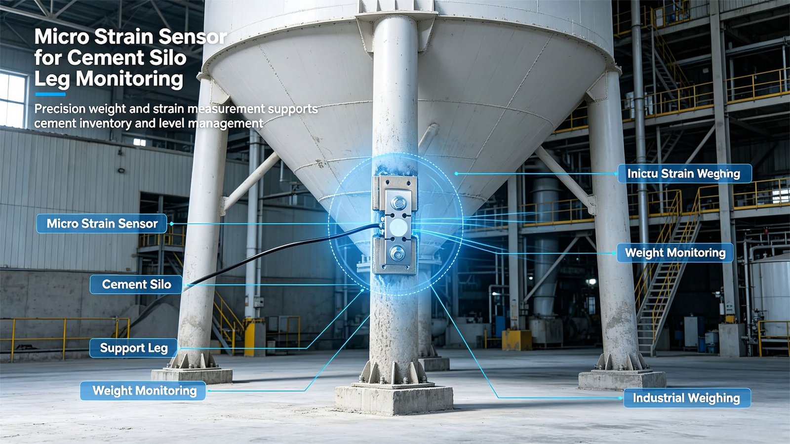
The plant’s maintenance lead found one of our application videos on YouTube — a strain sensor bolted onto the support leg of a cement silo, output climbing as the silo filled. That video did more selling than any brochure I have ever written. He sent it to me with one line: “Is this something you actually supply?”
It was. Here is the configuration we settled on after reviewing photos of his silo legs and the load data:
- 4 sensors per silo × 8 silos = 32 units of our weldable micro strain sensor (WST703), one on each support leg at matched height, all oriented to read axial compressive strain
- 8 digital weighing transmitters (WST1510, one per silo) summing the four leg signals, converting to 4–20 mA for the plant PLC and daisy-chaining RS485 Modbus RTU back to the control room
- Zero structural modification — sensors welded onto the clean section of each leg between flange plates; no cutting, no jacking, no cranes
- Installation spread over 6 working days, during normal production — the plant never stopped pouring
The sequence per silo took a crew of two technicians roughly half a day: grind and clean a patch on each leg, tack-weld the sensor mounting pads, run the weld straps, route shielded cable in conduit to the transmitter box, then move to the next silo while cement kept flowing through the first one.
That is the pitch. What follows is what actually went wrong, because this is the part every retrofit article skips.
4. How a Weldable Micro Strain Sensor Turns a Leg Into a Scale
The physics is straightforward once you see it. A loaded silo pushes down on its legs. Each leg stretches and compresses elastically — by a tiny amount, typically 100 to 1000 microstrain (με) at full load. A microstrain is one part per million: invisible to the eye, but perfectly measurable with a bonded strain gauge bridge.
Our WST703 packages that principle into a weldable housing that behaves like any industrial load cell electrically:
- A full Wheatstone bridge bonded inside a flexing center element, outputting 1.0–2.0 mV/V across the 300–1000 με measuring range — the same signal language as a standard load cell, so ordinary transmitters and indicators work without adaptation
- Two mounting pads that weld (or bolt, on the clamp variant) onto the leg face a fixed distance apart; as the leg compresses under load, the distance shrinks, the center element flexes, and the bridge output tracks the force
- IP65 sealing with silicone protection over the gauge cavity — cement dust and monsoon rain stay outside
- Creep of ±0.05% F.S / 30 min — critical for a sensor that sits loaded 24/7 for years; cheaper bonded-gauge designs drift visibly within a shift
Because each of the four legs carries roughly a quarter of the silo load, the four sensor signals are summed — in the transmitter or by paralleling in a junction box — to produce one silo-level weight signal.
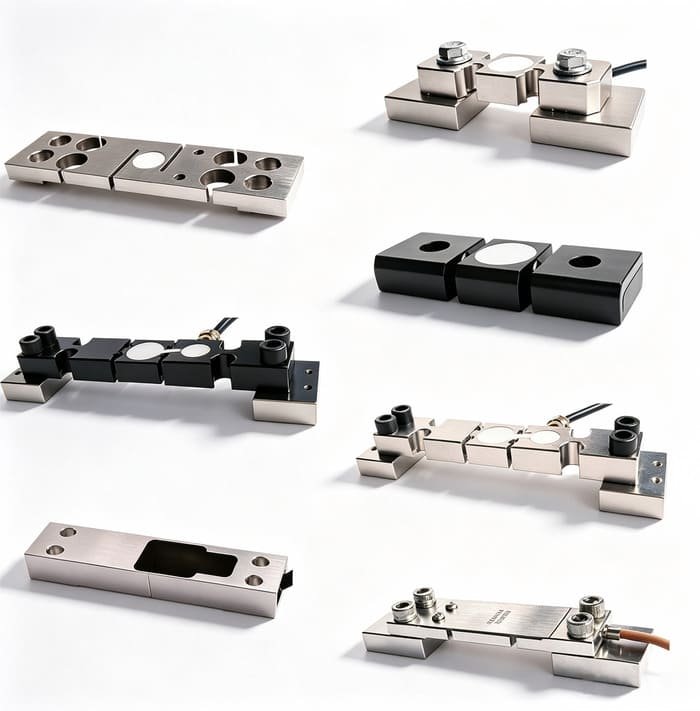
The WST703 micro strain sensor: two weldable mounting pads, one sealed full-bridge measuring element. Bolt-on clamp versions are available for structures where welding is not permitted.
Below is the actual application — the same installation method we used in Vietnam, on a cement silo leg. If you are evaluating this approach for your own plant, this clip answers most “how does it physically mount” questions:
Field installation on a cement silo support leg. A shorter vertical cut is available as a YouTube Short here.
5. Three Field Problems and How We Fixed Them
If retrofit strain weighing were as easy as “weld it on and read the number,” everyone would do it. Here are the three problems that actually cost us time on this project — and the fixes I now bake into every quote.
Problem 1: The hot-work permit nobody scoped
Week one, day two: the plant’s safety officer stopped our technicians at the foot of silo #3. Welding on a structure that stands above a custody area for a fine powder required a hot-work permit, a fire watch, and supervisor sign-off — none of which were in the installation plan, because I had assumed “weldable” meant “weld it whenever.”
Fix: we resequenced the work into short permit windows the plant already ran for routine maintenance, roughly two hours each morning. Each window covered one silo’s four legs. Total schedule slipped by two days — still zero production stoppage. For customers whose sites prohibit welding entirely, we now quote the bolt-on clamp variant as the default and offer welding as the upgrade, not the baseline.
Problem 2: The sun side reads differently from the shade side
Three weeks after commissioning, the plant called: silo #6’s reading dropped 4 tonnes overnight, then recovered by noon. Nothing had been discharged. The cause was thermal, not mechanical — the leg on the sun-facing side heats up, its zero point shifts (even a temperature-compensated bridge drifts a little across a 30°C surface temperature swing), and the summed total picked up the difference.
Fix, in three layers: first, all four sensors per silo were re-mounted at matched height on the same orientation so they share one thermal environment. Second, we enabled zero-tracking in the WST1510 transmitter with a window wide enough to absorb slow thermal drift but too slow to follow a real discharge. Third, the plant’s SCADA applies a 15-minute rolling average on displayed tonnage. Overnight swings dropped from ±4 t to under ±1 t — inside the ±2–3% accuracy band we had promised. The WST703’s compensation spec (±0.1% F.S per 10°C on both zero and output) does the heavy lifting; the system design just keeps what is left within budget.
Problem 3: Calibration — there are no load cells to compare against
This is the question every serious buyer asks: if the silo was never a scale, what do you calibrate it against? We could not hang test weights on a 200-tonne silo, and we were not going to hire a water truck. The answer turned out to be already parked outside the gate.
Fix: two-point calibration against the plant’s own paper trail. Point one: the empty-silo zero, captured after a verified complete discharge. Point two: over the following two weeks the plant received bulk cement trucks, each with a weighbridge ticket of known tonnage; we logged the sensor output before and after each pneumatic transfer into the silo. Twelve transfers gave us a clean gain factor — the slope between accumulated tonnes delivered and summed mV/V. The final linearity check came from the silo’s own discharge: the batch computer records exactly how much cement each concrete mix consumes, and the sensor tracked batch totals within 1.8%. I now include this calibration protocol as a one-page checklist with every silo retrofit quote.
A fourth issue worth mentioning: wind. An empty 200-tonne silo has a sail area, and gusts inject low-frequency noise into every leg. It never threatened accuracy once we set the transmitter’s damping correctly — the WST1510 samples at 1280 Hz internally, which is far more than tonnage needs but makes digital filtering easy. If your silos stand on an exposed coastal or highland site, tell your supplier early: damping settings and mounting height matter more there than sensor selection.
6. The Calibration Protocol, Summarized
For readers who want the short version to hand their maintenance team, here is the six-step protocol we now ship with every strain-based silo retrofit:
- Zero capture — record the all-leg summed output after a verified full discharge (or at commissioning, if the silo is known-empty)
- Reference accumulation — log weighbridge-verified inbound material over 5–15 transfer events, recording sensor output immediately before and after each transfer
- Gain calculation — linear regression of Δtonnes against ΔmV/V across events; discard any event where the transfer was interrupted
- Verification — cross-check against 5+ outbound batch or dispatch records
- Thermal soak — repeat the zero capture at two different times of day; accept the installation only if the zero spread sits inside your accuracy budget
- Schedule — re-verify zero and gain quarterly, and after any structural work, repainting, or sensor replacement
That last point about repainting is not theoretical. A year after our Vietnam install, the plant repainted the silo legs and the readings shifted about 2% until we re-zeroed — a fresh coat of paint is stiff enough to change the strain transfer path across the sensor pads. Put it in your maintenance SOP.
7. Where the Weighing Core Ends
I want to be precise about what we supplied on this project, because retrofit projects attract scope confusion:
We supply the weighing core: the strain sensors, the summing and signal conversion (transmitters, junction boxes), matched cabling guidance, the calibration protocol, and remote technical support during commissioning. We do not supply the silo, its modification, the hot-work execution, structural assessments, or the plant control system. Structural evaluation of an existing silo, welding procedure qualification, and PLC/SCADA integration belong to the plant’s local contractor and engineer of record. We make the legs measurable; we do not certify the legs.
This division is also why the approach works financially: the sensor kit is a small fraction of total project cost, and the customer’s own crew — who already hold the site permits — handles everything physical. Our Vietnamese contractor needed one remote video call from us to set transmitter parameters, and nothing since.
8. What I Would Specify Today
If you are planning a similar retrofit on silos, hoppers, or any structure where mounting a conventional load cell is impractical, here is the exact combination I would quote:
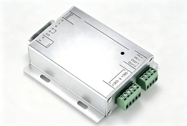
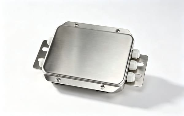
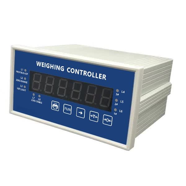
Read together, the four parts form one system: WST703 sensors turn leg strain into millivolts, WST1513 sums them passively (or WST1510 does it digitally and adds Modbus), and WST1505 puts the tonnage figure — plus relay alarms — in front of the operator. Pick the summing and display layer that fits the site: analog junction box with a panel indicator for a simple local readout, digital transmitters for SCADA integration, or both in parallel.
Bottom line: if your structure can accept two welded pads per load path, you already have a weighing system waiting — no cutting, no jacking, no shutdown. Mount all sensors at matched height and orientation, calibrate against paperwork you already trust, and re-verify after every repaint.
Frequently Asked Questions
Planning a Silo or Structure Retrofit?
Send us your leg cross-section photos and load data — we will recommend the sensor model, quantity per leg, and the calibration protocol for your structure, typically within one working day.