

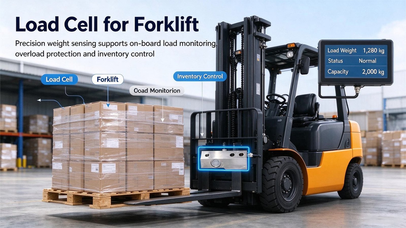
ONBOARD WEIGHING
LOAD MOMENT
Load Cells for Forklifts: The Weight Is the Easy Half
Every forklift scale on the market will tell you how many kilograms are on the forks. Almost none of them will tell you whether those kilograms are legal to lift on that truck, at that load centre, at that height. Here is where the sensors actually go, what each position costs you, and why a load cell must never become the weakest link in a lifting chain.
A forklift scale is being asked to do two jobs that pull in opposite directions. Job one is metrology: report the mass of the pallet truthfully enough to bill somebody for it. Job two is safety: tell the operator whether this load, in this geometry, is inside the truck’s rated capacity.
Almost every product on the market does job one. The accidents come from job two — because rated capacity is not a mass. It is a moment, and the moment depends on load centre, lift height, mast tilt and whatever attachment is bolted to the carriage. A 2,500 kg truck lifting 1,800 kg can be 15 % past its limit and the scale will still say “1,800 kg, all good.”
So this article is not really about load cells. It is about the six places you can put a sensor on a truck, which of them produce a number you can invoice against, which of them produce a number you can trust, and which of them turn a load cell into a load-bearing safety component that it was never designed to be.
2. The two questions it has to answer
3. Six places to put a sensor
4. The weighing plate and the load centre
5. The safety-factor wall
6. The hydraulic route, honestly
7. Three legal layers, only one is ours
8. Case: the scale was right, the load was illegal
9. Case: the 3 % that was a protocol
10. Case: measuring where the load is
11. The eight numbers I ask for
12. What we supply, what we do not
13. Questions I get asked
14. The parts
1. What a forklift scale actually is
A forklift scale is not a scale that happens to be on a forklift. It is a sensor package grafted onto a machine whose load chart was written before anyone thought about sensors — and that graft is where all the interesting engineering lives.
I have quoted these jobs for years and the pattern never changes. A customer writes in with a truck model and a capacity and asks for a load cell that can weigh it. Nine times out of ten, the truck model and capacity turn out to be the least useful two facts in the email.
A powered industrial truck is a counterbalanced lever. The front axle is the fulcrum, the load acts at the load centre, and the counterweight acts behind the axle. The whole safety question reduces to one inequality:
Truck moment − load moment ≥ 0 (the stability margin that ISO 3691-1 is built around)
Load moment is mass × horizontal distance from the fulcrum. Which means 1,000 kg at 500 mm exerts the same moment as 500 kg at 1,000 mm. That one sentence is why a mass-only scale is structurally incapable of answering the safety question.
There is a further wrinkle that catches out experienced fleet engineers. The number on the data plate — the one everybody quotes as “our truck is a 2.5 tonner” — is calculated under reference conditions: mast vertical, truck level, hard smooth floor, no attachment, no cross-slope, no wind, load evenly distributed at the stated load centre. Change one and the plate is no longer accurate for what you are doing. Change enough of them and it is not inaccurate, it is invalid.
| What the scale tells you | What the truck actually needs to know |
|---|---|
| Mass on the forks, in kg or lb | Load moment — mass × real load centre |
| A single threshold (“max 2,500 kg”) | A capacity that changes with lift height and tilt |
| Occasionally, a tare for the forks | A tare that stays right when somebody bolts a rotator on |
| A number, after the lift | A warning, before the load is off the ground |
That gap has a name in the standards world, and it is the vocabulary you need when specifying. A safe load indicator (SLI) measures the load and compares it to a fixed rated capacity. A load moment indicator (LMI) combines the load with the machine’s geometry — load centre, lift height, tilt — against a dynamic capacity chart. In Europe, EN 15000 covers both, and it is written for variable-reach trucks and telehandlers precisely because that is where a fixed threshold stops being meaningful. A counterbalance truck on level ground with a fixed mast and uniform pallets genuinely can get by with an SLI. The moment any of those conditions fails — and in a real yard one always does — you need the moment, not the mass.
2. The two questions a forklift scale has to answer
Whenever a customer asks me to help specify an onboard scale, I make them write down the two questions the number has to answer. Not “what do you want to weigh” — that is the easy part.
Q1 — How much is on the forks?
Q2 — May this truck lift it, here, like this?
Q1 is metrology. Q2 is a control problem. They have different accuracy requirements, different sensor placements, different certification paths and, critically, different failure consequences.
Getting Q1 wrong costs money. Bill a customer for 1,020 kg when it was 1,005 and you have a reconciliation conversation. Uncomfortable, but survivable.
Getting Q2 wrong costs people. The statistics get quoted loosely, so it is worth reading them carefully.
Forklift overturns are the leading cause of fatalities involving powered industrial trucks. Depending on how the data is sliced, overturns account for roughly 22 % to 42 % of forklift-related deaths — OSHA’s own guidance puts overturns at about 25 %, while other analyses of the same fatality population attribute up to 42 % to tip-over and subsequent crushing. The spread is not a contradiction; it is what happens when you count events versus count causes.
The number I find most useful comes from the Spanish national institute INSST: of all forklift overturn events, 51 % have serious consequences and 16 % are fatal. An overturn is close to a coin flip for “serious or worse.”
And the causes listed are almost all geometry, not mass: travelling with the load raised too high, excessive loads, cornering too fast, uneven ground. Only one of those four is a pure mass problem.
I want to be careful here, because the honest position is not “a scale prevents tip-overs.” It does not. A scale that reports mass accurately, on a truck whose operator is travelling with the load at two metres, has done nothing for safety. What a scale can do is remove one specific cause — the operator’s estimate of capacity being wrong — and only if the number it compares against is the right number for the geometry in front of it.
That is the whole article. Everything below is the mechanics of getting there.
3. Six places you can put a sensor on a truck
When I get a forklift weighing enquiry, the first thing I do is sketch where the sensor would physically sit. There are only a handful of options, and they produce genuinely different products. I will take them in order of how often customers ask, which is roughly the inverse of how well each answers Q2.
Position A — In the hydraulic circuit
A pressure transducer tees into the lift cylinder line. Fast, cheap, and nothing mechanical changes, so rated capacity is unchanged. Typical accuracy ±1–2 % of rated capacity. Full treatment in section 6.
Position B — A weighing plate between the carriage and the forks
The metrology answer: a steel plate with load cells built in, bolting to the carriage with the forks hooking onto the plate. Typical accuracy around ±0.1 % of capacity, and the only route certifiable for commercial transactions. Mettler Toledo’s 3-point suspension design and Rice Lake’s CLS carriage are the well-known examples.
What it costs you: the plate has thickness, so it pushes the load further from the mast. Moving the load centre from 500 mm to 560 mm costs 11 % of rated capacity before you pick anything up — the subject of section 4, and the most under-discussed consequence of buying a carriage scale.
Position C — Fork shoes or fork-heel pockets
Cells sit in shoes that slip over the existing forks, or in pockets machined into the heel. Nothing between carriage and load changes, so the truck’s geometry is preserved. The trade-off moves to the forks: you add mass and thickness at the very front of the moment arm, and the cells see the load through the fork’s own deflection.
Position D — In the lift chain path
The one people propose when they want the sensor out of the way, and the one I most often have to talk customers out of. The reason is arithmetic, not opinion — see section 5.
Position E — Below the hook, on an attachment
A jib, hook or spreader: the cell is in the attachment’s load path rather than the truck’s. Legitimate and common in yards, and where an S-type cell genuinely belongs — provided you derate it for lifting duty.
Position F — On the structure, measuring force rather than load
Not weighing at all. A through-hole washer-type sensor under a mast anchor bolt, a tilt-cylinder pin or a counterweight fixing, reporting whether that joint is carrying what it was designed to. This is the “safety monitoring” half of an onboard system — the half that watches the truck rather than the pallet. The distinction is not my invention; it is how this class of system is described by the suppliers who build them, and it is why one truck needs two different sensor types in two different places.
| Position | Typical accuracy | What it costs the truck | Trade-certifiable |
|---|---|---|---|
| A Hydraulic tee | ±1–2 % of capacity | No capacity loss; adds a fitting in a 3×-rated circuit | No |
| B Carriage weighing plate | ±0.1 % of capacity | Load centre pushed forward; plate mass subtracted from payload | Yes |
| C Fork shoes / heel pockets | ±0.1–0.5 % | Mass and thickness at the fork tip; slightly reduced net capacity | Usually |
| D Lift chain path | Good on paper | Reduces the lifting assembly’s safety factor. Not acceptable. | Not relevant — it should not be done |
| E Below the hook | ±0.05–0.2 % (after derating) | Nothing — but the cell must be derated for lifting duty | Possible as a separate instrument |
| F Structural / bolt force | Not a weighing spec | Nothing, if installed as a monitor only | No — it is a monitor, not an instrument |
Rule of thumb I use when quoting. If the customer needs a number they can invoice against, the sensor goes in position B or C and they accept a capacity re-rate. If they need an overload alarm and nothing else, position A is cheaper and perfectly adequate. If they want the sensor out of the way entirely, they are asking for position D, and the answer is no.
4. The weighing plate, and the load centre it silently steals
Position B is where the customer is most likely to spend real money and most likely to be surprised afterwards, so it gets its own section.
The mechanism is simple. A load’s capacity rating is set at a stated load centre — the horizontal distance from the fork face to the load’s centre of gravity. For most counterbalance trucks that reference is 500 mm, reflecting a standard 1,200 × 1,000 mm pallet; for reach trucks it is commonly 600 mm. When the actual load centre is larger, capacity derates roughly in inverse proportion:
Capacitynew = Capacityrated × (LCrated ÷ LCactual)
Exact for the pure moment term only; real load charts also carry a lift-height derate, which you read off the OEM curve rather than extrapolate.
Now put the weighing plate into that equation. A plate adding 60 mm of thickness in front of the carriage does not just add its own weight — it moves every load you will ever lift 60 mm further out.
| Configuration on a 2,500 kg / 500 mm truck | Real load centre | Derated capacity |
|---|---|---|
| Bare carriage, 1,200 × 1,000 mm pallet | 500 mm | 2,500 kg |
| + weighing plate, 60 mm | 560 mm | 2,232 kg (−10.7 %) |
| + weighing plate, and a 1,200 × 1,200 mm bulk bag | 660 mm | 1,894 kg (−24.2 %) |
| + weighing plate and a 180 mm sideshifter | 740 mm | 1,689 kg (−32.4 %) |
| + plate, sideshifter, and an 800 mm-centre steel coil | 980 mm | 1,276 kg (−49 %) |
That last row is not a thought experiment. Unwound coils, pipes, long lumber and oversized bulk bags routinely push real load centres to 700–800 mm, and a 15 m container mast can lose around a third of its base capacity from height derate alone. The compounding is what gets people: no single term looks frightening, and the product does.
And note what the scale says in every one of those rows. It says “2,400 kg — OK.” Because the scale measures mass. The 2,400 kg is real. It is also 1,124 kg past what the truck may lift. That is the failure mode this article exists to point at.
The mounting standard you will be asked about
If you are building a weighing plate, you will need to build it to a carriage class. Forks are standardised under ITA / ISO 2328 (and ANSI B56.11.4 in North America), and the classes are defined by carriage bar height and hook spacing — so a plate that fits a Class II truck will not fit a Class IV truck, and the fleet spec you send me has to say which.
| Class | Carriage height | Truck capacity | Hook spacing |
|---|---|---|---|
| Class I | 331 mm / 13″ | up to ~1,000 kg | — |
| Class II | 407 mm / 16″ | 1,000–2,500 kg | 114 mm |
| Class III | 508 mm / 20″ | 2,500–5,000 kg | 140 mm |
| Class IV | 635 mm / 25″ | 5,000–8,000 kg | 178 mm |
| Class V | 728 mm / 28.7″ | 8,000–11,000 kg | — |
Two traps live in that table and both come up in every fleet enquiry I have handled. First, capacity is a poor guide to class: newer Hyster and Yale trucks rated around 10,000–11,000 lb often carry a Class IV carriage, and 4-stage (quad) mast trucks generally run one class smaller than their capacity suggests — a 6,500–7,000 lb quad-mast truck is typically Class II. Second, pin-type or shaft-mount forks sit outside this standard entirely, so the class does not apply and you measure shaft diameter and fork spread instead. If you are sending me a drawing, the carriage measurement is the truth and the capacity is only a first guess.
5. The safety-factor wall: why a load cell does not belong in the lifting path
Position D is the one I most often refuse, and the request is entirely reasonable on its face: “Put the sensor in the chain. It is out of the way, it never gets hit, and nothing hangs off the carriage.” The problem is that a forklift lift chain is not convenient real estate. It is a fatigue-rated safety component with its own design factor.
Mast lift chains are leaf chains, standardised under ASME B29.8 (dimensionally ISO 4347, with EN 14659 covering inspection in Europe). What surprises most engineers the first time they see it is that the allowable working load of a leaf chain in lifting service is only about 25 % of its minimum break load — a design factor of 4:1, with some lift-duty guidance pushing to 5:1. That is a much larger margin than most general lifting tackle uses, and the reason is not static strength. It is fatigue.
Truck rated 2,500 kg · carriage + forks 350 kg · two chain strands
Total lifted mass = 2,850 kg = 27.95 kN
Per strand at rated load = 27.95 ÷ 2 = 13.98 kN
Common chain for this class (BL1022): minimum break load 222 kN, allowable working load 55.5 kN → utilisation at rated capacity about 25 %
Now insert a general-purpose S-type load cell into that strand. Take a 20 kN cell, with the datasheet numbers every catalogue carries: safe overload 150 % of rated capacity, ultimate overload 200 %.
| Quantity | Chain alone | Chain + 20 kN S-type cell |
|---|---|---|
| Ultimate / break strength of the weakest element | 222 kN | 40 kN (the cell) |
| Allowable working load at 4:1 | 55.5 kN | 10.0 kN |
| Actual force at rated truck capacity | 13.98 kN (25 % of limit) | 13.98 kN — 140 % of limit |
| Safety factor against break, at rated load | 15.9:1 | 2.9:1 |
With a 20 kN general-purpose load cell in the chain, the lifting assembly’s allowable working load drops to 10 kN — and the truck pulls 13.98 kN per strand at its rated capacity. The truck would be operating above its own lifting assembly’s working load limit before anyone overloaded it, and the safety factor against break falls from roughly 16:1 to 2.9:1.
“But it will never actually break” is true and beside the point. Leaf chain does not normally fail by being pulled apart. Field analysis of properly rated lifting systems attributes the large majority of failures — well over 80 % — to fatigue cracking in the link plates rather than single-event overload. Those cracks begin at 0.2–0.5 mm and are essentially invisible until they have propagated through a large fraction of the section. And the cycle count is not small: 60 lifts an hour over an eight-hour shift is 480 tension cycles a day, around 125,000 a year.
So the answer to position D is not that our cells are not good enough. Our cells are fine. The answer is that a general-purpose weighing load cell is not a lifting component, and I am not willing to have one become the weakest link in a chain holding two and a half tonnes over somebody’s head. If you need chain force for maintenance or research, measure it with the truck empty, or measure cylinder pressure instead.
Below the hook is different — and has its own rule
Position E is legitimate, because the cell is in the attachment’s load path and the attachment’s rating governs. But it does not escape derating, so here is the rule I give customers. If the application needs a 4:1 lifting design factor, and your cell has an ultimate overload of 200 % of rated capacity, the cell’s rated capacity must be at least four times the working load you intend to hang on it. A 200 kN cell therefore gives a working load limit of about 50 kN, or 5.1 tonnes — not 20 tonnes. That surprise is exactly why dedicated crane scales and load links publish their own safety factors rather than quoting the cell rating. A datasheet showing safe overload 150 % and ultimate 200 % is telling you it is a force sensor, not a lifting appliance.
6. The hydraulic route, described fairly
I sell load cells, so you would expect me to be dismissive about pressure transducers. I am not, and I will tell you where I recommend them, because a customer who buys the wrong thing from me does not come back.
The hydraulic route taps the lift cylinder line and converts pressure into weight. It adds no mass to the carriage, needs no structural modification, and typically lands at ±1–2 % of rated capacity. Those numbers are honest, and the vendors in that segment publish them honestly — the systems that cannot be certified for trade say so.
What you are buying is a pressure reading, and pressure equals load only under conditions nobody usually writes down. The clearest statement of the problem I have seen came from a hydraulic-scale manufacturer explaining why they abandoned the conventional approach. Their own words: a single static pressure reading suffers “considerable error from valve opening and closing technique, tilt, lift height, bearing hang-ups.” That is an unusually candid list from someone selling the technology, and every item is real:
- Mast tilt. Tilt changes the load’s moment arm, and therefore the cylinder force. On the truck side each forward degree is worth roughly 3 % of capacity; on the measurement side it simply moves your reading.
- Lift height. Chain and anchor geometry change with height, so the same pallet weighs differently at 300 mm and at 1,200 mm.
- Friction and bearing hang-ups. Friction is direction-dependent, so a load weighed going up and the same load coming down do not agree. This is my most useful diagnostic: if the reading differs systematically by lift direction, you are looking at friction, not a sensor fault.
- Oil temperature. Viscosity and seal leakage both move with temperature. A truck reading 1 % high cold can read 2 % high after four hours. In a cold store at −20 °C this term is not a refinement, it is the dominant one.
- The fittings themselves. A safety point rather than an accuracy one, straight out of the machine standard: ISO 3691-1 requires hydraulic hoses, pipes and fittings to withstand at least three times the working pressure without rupture or deformation. A tee and a transducer in a lift circuit are pressure parts, not plumbing accessories.
Better hydraulic systems work around the static-reading problem by weighing dynamically — opening a bypass so the load descends slowly while the transducer samples, then averaging. One vendor describes roughly 150 pressure values per second over a five-second lowering stroke, about 750 samples, and claims 0.2 % of rated load as a result. Their honest figure for a large truck is different: on a 20,000 lb machine, “within 500 lb of any load you pick up.” That is 2.5 % of capacity — and note the phrasing, within, with no claim about where in that band an individual reading will fall.
Where I recommend hydraulic, and where I do not.
✓ Overload alarm on a yard truck — a 2 % band around rated capacity is a perfectly good threshold.
✓ Operators who need “roughly 400 or roughly 900 kg” for load planning.
✓ Leased fleets with carriage-return conditions that rule out modification.
✗ Anything invoiced against. Hydraulic systems are not certifiable for legal-for-trade use and no calibration changes that.
✗ Any site where the number must mean the same thing in January and July, or on day and night shift, without a written protocol enforcing identical mast conditions.
7. Three legal layers, and only one of them is ours
This determines what is even possible. Putting a weighing system on a forklift exposes you to three separate regulatory regimes, administered by different people on different continents. Only one of the three is a conversation a sensor supplier can have with you.
Layer 1 — Metrology: is the number legally a weight?
If the reading determines what somebody pays, in most of Europe you are building a non-automatic weighing instrument (NAWI): OIML R76 as the international recommendation, EN 45501:2015 as the harmonised European standard derived from it, and MID 2014/32/EU Annex MI-006 as the directive. The instrument carries a class — most industrial and vehicle scales are Class III — with intervals defined as n = Max ÷ e, where e is the verification scale interval that tolerances are expressed in.
One detail worth internalising: the displayed resolution d may be finer than the legal verification interval e. A scale can legally show you a number the law does not guarantee, because maximum permissible errors are expressed in multiples of e, not d. When comparing two systems on paper, check which interval the accuracy claim is quoted against.
The good news for component buyers is the modular approach. Instead of type-approving a whole instrument, individual modules — load cells, indicators, peripherals — can be tested and issued their own certificates, which are then quoted in the instrument’s type approval. Load cells are approved against OIML R60; complete NAWIs and other modules against R76. That is the layer where a component supplier can genuinely help, with real documentation. What it is not is a whole-scale approval: a component certificate is one input to your file, and full NAWI approval involves a Notified Body, an EU type examination and typically a conformity module on top — B plus D, or B plus F.
Layer 2 — Machinery: is the truck still the truck that was approved?
The truck is a machine under ISO 3691-1, with the series extending to ISO 3691-2 for variable reach and ISO 3691-4 for driverless trucks; EN 15000 covers safe load indicators and load moment indicators for variable-reach machines. Around all of it sits the EU machinery legislation.
The timing matters if you are planning a product rather than a single retrofit. Directive 2006/42/EC applies until 19 January 2027. From 20 January 2027, Regulation (EU) 2023/1230 applies on a mandatory basis and the Directive is repealed — and the Commission is explicit that there is no transitional window in which either text may be applied. Anyone launching a forklift weighing product into the EU in the next year should be building to the Regulation.
The Commission’s own guidance states that the machinery legislation applies to products placed on the EU market for the first time or when existing machinery is modified to such an extent that it becomes de facto new machinery.
A weighing plate that shifts the load centre and forces the capacity plate to be re-issued is not cosmetic. Whether it crosses that line is a judgement for a conformity assessment professional, and not one I am qualified to make on your behalf — but you should know the question exists, and nobody asking it is being difficult.
A handful of ISO 3691-1 requirements set the outer limits on what you can design: the lifting mechanism must have a safety factor established by the chain supplier’s break-load certificate; lowering speed at rated load is capped at 0.6 m/s; hydraulic parts must take three times working pressure; overhead guards per ISO 6055 are required above 1,800 mm. None are ours to satisfy, but all constrain what we can hand you.
Layer 3 — Workplace: may your operator lift it at all?
OSHA 29 CFR 1910.178(a)(4) is the paragraph to know: modifications and additions which affect capacity and safe operation shall not be performed by the customer or user without the manufacturer’s prior written approval, and the capacity and instruction plates shall be changed accordingly. Paragraph (a)(5) requires front-end attachments to be marked with the approximate weight of the truck and attachment combination at maximum elevation, and (q)(6) prohibits altering the relative positions of parts, adding parts not provided by the manufacturer, or adding counterweight, without approval.
There is a workable escape hatch. In a 2004 interpretation letter OSHA confirmed that where the manufacturer refuses or does not respond, written approval from a qualified Registered Professional Engineer, supported by a safety analysis of the manufacturer’s objections, is treated as a de minimis violation rather than a citation. Note that the engineer, not the scale vendor, carries it. Elsewhere the pattern repeats locally: ANSI/ITSDF B56.1 Part II “For the User” governs retrofits in North America and is freely downloadable; AS 2359.2-2013 in Australia requires each attachment to carry its own manufacturer-issued data plate with the derated capacity; LOLER applies in the UK; and ATEX certification covers the whole system in explosive atmospheres, which narrows component choice considerably.
| Layer | Applies to | Who owns the process |
|---|---|---|
| Metrology OIML R76, EN 45501, MID MI-006 |
The weighing instrument, if the number is used for trade | You, with a Notified Body. We supply component-level certificates (load cells to OIML R60) that feed your file. |
| Machinery ISO 3691-1, EN 15000, EU 2023/1230 |
The truck as a machine, including its stated capacity and load chart | The truck OEM or the modifying party. Not us — we do not modify trucks and cannot re-issue a load chart. |
| Workplace OSHA 1910.178, B56.1, AS 2359.2 |
The employer operating the truck, and the truck’s markings | The employer, with the manufacturer or a qualified PE. Not us. |
Which produces the sentence that has cost me more deals than anything else I say: we can supply the sensing layer and the evidence that goes with it, and we cannot approve your truck. If a supplier tells you otherwise, ask them which Notified Body issued their whole-scale approval.
8. Case: the scale was right and the load was illegal
Netherlands, 2023. A third-party logistics operator, twelve counterbalance trucks, mixed 2.5 t and 3.5 t.
They came to me because they had already bought carriage scales — not from us — on twelve trucks, and after eight months they had two problems they could not explain. First, the same pallet gave different readings on different trucks, up to about 0.9 % apart. Second, one large customer had started disputing shipments on a recurring SKU, claiming short weight.
Their hypothesis was drift, and they wanted a quote for replacements.
Before quoting I asked for one afternoon on site with a test weight set. We put a certified 1,000 kg on three different trucks and all three read within 0.15 %. The scales were not drifting. They were not the problem, and I said so — which is not the most commercially obvious thing to do on a first visit.
The problem was on the trucks, in a place nobody had looked. Eight of the twelve had bare carriages. Four had sideshifters. A typical sideshifter frame is around 180 mm thick. Add the 60 mm weighing plate that was already fitted and those four trucks were running a load centre of roughly 740 mm against a rated 500 mm.
2,500 kg × (500 ÷ 740) = 1,689 kg real limit
The scale was displaying 2,400 kg and reporting it as within capacity.
Seven hundred and eleven kilograms of load, per lift, illegal for eight months, on four trucks, with a weighing system whose job was specifically to prevent it. And it explains the “short shipments” too, which is the part that had confused them: on the sideshifter trucks, operators had learned that the trucks felt light, so they were loading more onto the pallets than they should have been. The customer disputes were not a weighing error at all. They were a consequence of the load being subdivided differently.
The fix cost them almost nothing, because it was software and configuration:
- A load-centre field on the weighing terminal. The operator enters the pallet depth, and the system selects the correct column instead of comparing everything to one number.
- A per-truck derated capacity, calculated once from the truck’s actual carriage configuration and stored against the truck ID. Four trucks got one number, eight got another.
- The overload alarm was re-pointed at the derated figure rather than the nameplate figure.
- Data plates re-issued, as 1910.178(a)(4) and AS 2359.2 both require.
Over-capacity lifts went from a daily occurrence to effectively zero, and the customer disputes stopped. Nothing was replaced. Twelve scales, four sideshifters, one missing configuration field.
What I took from it. Almost every “the scale is wrong” complaint I have investigated in this industry turned out to be a comparison problem, not a measurement problem. The instrument measured the right thing accurately. The system compared it against a number that had stopped being true the day somebody bolted a sideshifter on. If you are specifying a forklift scale, the single highest-value feature you can ask for is not a better load cell. It is a per-truck capacity that reflects the truck as configured.
9. Case: the 3 % that was a protocol, not a part
Türkiye, 2024. An automotive components plant, eight counterbalance trucks, hydraulic pressure scales.
They rang up wanting to replace all eight with load cell systems. The complaint was specific: the scales read high in the afternoon, and the night shift consistently got different numbers from the day shift. They had already decided they needed better hardware.
I asked them to do something before I quoted: weigh one load five times under five different mast conditions, and write down every number. This is the single cheapest diagnostic in onboard weighing and it takes twenty minutes. Here is what came back, normalised against their own reference condition:
| Same load, different mast condition | Reading vs reference |
|---|---|
| Mast vertical, load at 300 mm, stationary (reference) | 0 |
| Mast vertical, load raised to 1,200 mm | +1.4 % |
| Mast tilted back 6° | −0.9 % |
| Mast tilted forward 3° | +2.6 % |
| Oil at 18 °C (morning) vs 46 °C (afternoon) | +1.1 % |
| Total spread | 3.1 % |
Their scales were performing exactly as hydraulic scales perform. Nothing was broken. The reading was a pressure, and pressure depends on geometry and temperature — and nobody had written down which geometry and which temperature the number was valid at. The afternoon drift was oil temperature. The shift-to-shift difference was that the day shift weighed with the mast vertical at low height and the night shift weighed whenever the load happened to be, which was usually higher and often tilted.
The fix was a written procedure and about an hour of training:
- Mast vertical, load raised about 300 mm, truck stationary, engine at idle.
- Hold the load three seconds before reading, so the reading settles under friction rather than mid-motion.
- A daily two-point check against a known weight — a forklift test weight if they had one, or a pallet of bagged product weighed once on a floor scale.
The spread fell from 3.1 % to 1.1 %, and the shift-to-shift discrepancy disappeared.
Then I told them not to buy anything from me.
Their actual requirement was an overload alarm in a parts yard, where the consequence of a 1 % error is a slightly over-spec lift. At 1.1 % spread, the hydraulic system they already owned was fit for that purpose, and replacing eight systems would have bought them accuracy they had no use for. They kept their scales. Fourteen months later they came back with a coil-handling problem, which is the next case, and I have no evidence those two facts are related — but I am not going to pretend I have never noticed the pattern.
What I took from it. Hydraulic scales are not inaccurate so much as unqualified. They tell the truth about pressure under all conditions; they only tell the truth about mass under one set of conditions, and if you never specify which set, your two shifts will disagree forever. A written protocol is worth more accuracy than a hardware upgrade, and it costs a training hour. Residual spread after the protocol — the 1.1 % — is exactly why these systems cannot be certified for trade, and no protocol will change that.
10. Case: measuring where the load is, not just how much
Steel service centre, Poland, 2025. Fourteen trucks, coils and plates, two near misses in one quarter.
Both near misses had the same shape. The operator lifted a coil, felt the truck go light at the rear, and set it down. Both coils were under the nameplate rating — a 2,500 kg truck, a coil of about 1,850 kg, and an operator entirely reasonable in believing it was fine, because 1,850 is less than 2,500.
It was not fine. Coils carried eye-horizontal sit a long way out, and long stock pushes load centres to 700–800 mm routinely. At 800 mm:
2,500 kg × (500 ÷ 800) = 1,562 kg actual limit
Load lifted: 1,850 kg — about 18 % over the real limit, and simultaneously 26 % below the number the operator was looking at.
The plant’s first proposal was to buy bigger trucks. For fourteen trucks that is an enormous capital line, and it does not fix the problem — it moves the threshold, and someone will eventually find a bigger coil.
What I proposed instead was to change what the weighing plate measures: not just the total, but the distribution. Put load cells in two rows, front and rear, separated by a known distance. Now you have two independent forces instead of one sum, and two forces at a known separation give you the position of the centre of gravity by simple moments. Taking moments about the front row, with the rows 400 mm apart:
Total mass F = A + B (A = front row, B = rear row)
d = (B × 400) ÷ (A + B) — distance of the centre of gravity from the front row
Add the fixed offset from the fork face and you have the effective load centre for that specific lift — not the pallet’s nominal one.
Multiply mass by distance and you have the moment. Compare the moment against the truck’s real load chart, at the measured height, and you have converted a safe load indicator into a load moment indicator — using nothing but load cells and arithmetic, with no boom angle sensor and no geometry model. That is the whole trick, and it is what I would build into any forklift scale where the customer’s loads vary in footprint. It costs a second row of cells and one more channel per plate.
What we supplied for that build:
- WST301 shear beam cells in each row — two per row, four per plate, matched as a set. Shear beam rather than single point, because on a plate this size a single-point cell cannot be shared across a rigid structure without the cells fighting each other for the load.
- WST1513 stainless multi-channel junction box for summing and trimming. The front and rear rows have to be trimmed independently — trim them as one group and you destroy the very information the second row exists to capture. A 4-channel box on a 2×2 grid gives you both axes.
- An indicator with enough channels to keep the rows separate rather than a single summed input, and enough maths to run the comparison on board.
Over-limit lifts started being flagged before the load came off the ground, which is the only timing that matters. The two near misses turned out to be one coil pattern repeated, and tagging it took the alarm count from thirty-odd a month to under five — and those five were genuine.
Two honest limits on the method. First, two rows give you the longitudinal centre of gravity; if lateral stability is the concern — and on a counterbalance truck it often is, because most tip-overs are sideways — you need the 2×2 grid and four separate channels. Second, the system does not know lift height unless you tell it, and height derate is worth up to a third of base capacity on a tall container mast. A moment comparison that ignores height beats a mass comparison, but it is not complete.
What I took from it. A load cell is a single-axis force sensor, and one force sensor can only ever produce one number. The truck’s problem needs two numbers multiplied together. The cheapest way to bridge that gap is not a better cell — it is a second cell, in the right place, plus the arithmetic to use it. Everything in this article that sounds like product selection is downstream of that one idea.
11. The eight numbers I ask for before I quote
Almost every forklift weighing enquiry starts with a truck model and a capacity, and those are the two facts I use least. Here is the list I actually work from. Send me these eight and I can usually come back with a real specification in a day instead of a week of back-and-forth.
- The data plate, photographed. I want Q (rated capacity), c (rated load centre), mast type, and the lift height at which Q is valid. The derate chart on the plate is where the real answer lives.
- Carriage class and measurement. ITA / ISO 2328 class, carriage bar height, hook spacing, and whether the forks are hook-mount or pin/shaft-mount. If pin-mount, the class does not apply and I need shaft diameter and spread instead.
- Every attachment currently fitted, with its mass and thickness — sideshifter, positioner, rotator, clamp, fork extensions. A 180 mm sideshifter is worth roughly a quarter of your capacity and I cannot see it from a model number.
- The real load centres you handle, worst case and typical. Measure the deepest load rather than using the pallet’s nominal size. Coils, pipes, bulk bags and doubled pallets all break the 500 mm assumption.
- Lift heights you actually work at, not the mast’s maximum. Height derate compounds with load centre.
- How many channels, and where the summing box can live. The item customers most often leave out and the one that most often delays a build. A carriage-mounted plate needs cable routing that survives mast flex — a mechanical problem in your design, and far cheaper to solve early.
- Environment. Indoor warehouse, outdoor yard, cold store, food plant with washdown, or explosive atmosphere. Our standard cells are IP65 — a splash rating — with PVC-jacketed cable, and that is not a specification for a wet yard in February.
- What the number is for. Invoicing, an overload alarm, WMS capture, or all three. This single answer decides the whole architecture and is the question that changes my recommendation most often.
Then I run the electrical budget, mostly to confirm the electronics are not worth worrying about. A 2,500 kg truck with a 400 kg weighing plate and a 350 kg carriage and fork set puts 3,250 kg across four points, so about 812 kg per cell — which puts 2 tonne cells at roughly 41 % of range, inside the 40–80 % band I like to work in.
Four WST301 cells at 2.0 mV/V, 10 V excitation:
20 mV per cell at 2,000 kg → four in parallel give 20 mV across 8,000 kg → 2.5 nV per gram
A 24-bit converter over a ±10 mV span with 5,000,000 counts resolves about 4 nV → roughly 1.6 g per count, about 625 counts per kilogram
So the plate can electrically resolve a 5 kg increment with roughly 1,600 counts behind it — three orders of magnitude of headroom. When a customer tells me their forklift scale is not accurate enough, I know before opening the email that the problem is not the load cell. Load centre, lift height and mast tilt move that reading by percent. The electronics move it by grammes. Spend your engineering budget where the error is.
One more question, and it is not technical. Who signs off the truck modification? If that is unclear, stop and clarify it, because everything downstream — plate design, capacity plate, load chart, insurance position — hangs off that name. I have seen a well-engineered weighing system sit in a warehouse for eight months because nobody would put their signature on the capacity plate.
12. What we supply, and what we deliberately do not
I sell weighing components, not forklifts and not complete weighing systems. That is not a marketing hedge — it is the single most useful thing to understand about working with us, because it is exactly where the responsibility line falls in the three legal layers above.
| What we supply | What we do not supply |
|---|---|
| Load cells, matched as a set, with the matching data written down — shear beam for fork-side weighing, double-ended shear beam (WST1406) if your project is onboard payload weighing instead | Approval to modify your truck, or a revised load chart |
| Multi-channel junction boxes with independent trimming per channel | The weighing plate structure itself — we support your design, we do not fabricate it |
| Indicators and transmitters — RS-485 / Modbus and 4–20 mA outputs for your WMS or PLC (WST1502 stainless indicator, WST1508 transmitter) | CE conformity assessment or machinery type examination of the modified truck |
| Component-level metrology certificates where applicable — load cells against OIML R60 | Whole-instrument NAWI type approval, or the Notified Body process around it |
| The arithmetic: capacity sizing, load-centre derating, error budgets, cable and channel planning | Stability re-testing, or the engineering sign-off described in layer 3 |
| Custom ranges, dimensions and cable lengths where the standard part will not fit | A legal-for-trade guarantee on any instrument we did not certify, because we cannot give one |
And four things I would rather say out loud than let you find out later.
1. WST505 is on your list, and it is not a weighing sensor. It is a through-hole washer-type compression sensor, 120 kN to 400 kN — 12 to 40 tonnes per unit — with a comprehensive error of 0.1 % of full scale and an ultimate overload of only 120 % of rated capacity. That last number disqualifies it from any weighing role on a truck: a 20 % margin over full scale will not survive a forklift. Its real home is position F — under a mast anchor bolt, on a tilt-cylinder pin, on a counterweight fixing — reporting whether a joint is carrying what it was designed to carry. That is a monitor, not an instrument, and a useful job. It is just not the job in the enquiry.
2. WST1501 is an indoor bench indicator, and a forklift is not a bench. Its operating range is 0 °C to 40 °C, its housing is plastic, and its display accuracy is 1/3000. On a truck in a cold store, a wet yard or a food plant it is the wrong part, and bolted to a mast it will be the first thing to fail. Put WST1501 in the fixed weigh station at the dock, where it is excellent value, and use our WST1502 stainless indicator with an RS-485 output on the truck.
3. Our standard cable is PVC, and IP65 is a splash rating. If your trucks run in a wet yard, a cold store or a plant that hoses equipment down, say so at enquiry stage. IP65 and a PVC jacket are fine for a covered loading dock and not fine for a decade of daily exposure. It is much cheaper to specify a different jacket and gland arrangement now than to discover it in year three.
4. A weighing plate eats load centre, and we cannot give you back the capacity. Everything in section 4 is real: thickness becomes a derate, and the derate compounds with attachments and height. We will do that arithmetic with you and give you a number, and that number will sometimes mean your existing trucks cannot carry what you thought they could. I would rather be the person who told you.
What that adds up to is a simple proposition. If you want to build a forklift weighing system, a load-monitoring system, or both, we can supply the sensing layer, the summing layer and the arithmetic, with component documentation that survives an audit and honest numbers about what each option can do. The truck — its capacity, its stability, its conformity, its plate — stays yours. That division of labour is what makes the project safe, and it is the only one I am prepared to work in.
13. Questions I get asked about forklift weighing
What accuracy can I expect from a load cell forklift scale versus a hydraulic one?
A carriage-mounted load cell system typically lands around ±0.1 % of capacity; a hydraulic pressure system at ±1–2 % of rated capacity, with the better dynamic-sampling versions claiming 0.2 % of rated load and honest large-truck figures quoted as “within 500 lb” on a 20,000 lb machine. The gap is real, but work out what your application needs before paying for it. For an overload alarm, 1 % is fine and hydraulic is the right buy. For an invoice, you need the load cell route and its certification.
Can a forklift scale be used for legal-for-trade billing?
Yes, but only certified configurations, and the certification is the whole point. Hydraulic systems are not certifiable for trade — a limitation of the measurement principle, not a calibration problem. Load cell carriage systems can be. In Europe the framework is OIML R76, EN 45501:2015 and MID 2014/32/EU Annex MI-006, with a Notified Body and an EU type examination usually plus a conformity module. We can supply load cells with component-level OIML R60 documentation. We cannot obtain the instrument approval, and any supplier who says they can should be asked which Notified Body issued it.
Will adding a scale reduce my forklift’s lifting capacity?
It depends where the sensor goes, and this is the question customers most often get wrong. A hydraulic tee adds no mass to the carriage and no thickness in front of it, so capacity is unchanged. A carriage weighing plate does both. A 60 mm plate on a 2,500 kg / 500 mm truck takes you to 560 mm and roughly 2,232 kg — about 10.7 % of rated capacity gone, and over a third once a sideshifter is added. Either way the capacity plate must be re-issued; under OSHA 1910.178(a)(4) that is not optional.
Where do the load cells actually go on a forklift?
Six realistic positions: in the hydraulic lift circuit (a pressure transducer, not a load cell); in a weighing plate between carriage and forks; in fork shoes or heel pockets; in the lift chain path; below the hook on an attachment; and on the structure measuring bolt or pin force. The first three are weighing positions. The fifth suits attachments if derated for lifting duty. The fourth should not be done — a general-purpose cell with 150 % safe overload would become the weakest link in an assembly designed at 4:1 or better. The sixth is structural monitoring, not weighing.
Can I retrofit a scale to an existing truck, or do I need a new one?
You can retrofit, and most of the market is retrofits — but retrofitting is a modification in the regulatory sense. Under OSHA 1910.178(a)(4), modifications affecting capacity and safe operation need the manufacturer’s prior written approval, and the plates must be changed to match. If the manufacturer declines or does not answer, OSHA’s 2004 interpretation allows written approval from a qualified Registered Professional Engineer with a supporting safety analysis, treated as a de minimis violation. Budget time for this step; it holds up more retrofits than any technical issue.
Does the scale tell me whether the load is safe to lift?
Usually not, and this is the most important thing in this article. A conventional scale outputs mass compared against a single fixed threshold, but rated capacity is a moment, not a mass — it changes with load centre, lift height and mast tilt. A 2,500 kg truck lifting 1,850 kg at an 800 mm load centre is about 18 % past its real limit while reading 26 % below the number the operator sees. Answering the safety question needs the moment, which means measuring the load’s position as well as its size. Ask any supplier which of the two they are selling you.
Which load cell do I actually need for a forklift scale?
For a weighing plate or fork shoes, a shear beam cell — our WST301 and WST302. Shear beam rather than single point, because on a rigid plate spanning a carriage the cells must load independently without fighting each other, and shear beam tolerates side and eccentric loads far better. Size so the working load sits in the 40–80 % band: a 2,500 kg truck with a 400 kg plate and 350 kg carriage puts about 812 kg on each of four cells, so 2 tonne cells land at about 41 %. Where the load footprint varies, use two rows of cells to compute load centre, with a multi-channel junction box so each row trims separately.
Can I weigh the load while the truck is moving?
Not usefully, and anyone promising it is selling you a filtered number rather than a measurement. Acceleration in any direction adds a pseudo-force, friction is direction-dependent so lifting and lowering disagree, and floor irregularities inject impulses. The industry-standard answer is a static condition: mast vertical, load raised to a defined height, truck stationary, one reading after the value settles. If you need continuous monitoring while travelling, that is a load-monitoring function rather than a weighing function, and it should be designed as one — with a deliberately chosen filter, and the acceptance that you have traded accuracy for responsiveness.
14. The parts I would quote for a forklift weighing build
Six parts, and one of them is in this list specifically so that I can tell you not to use it as a scale.

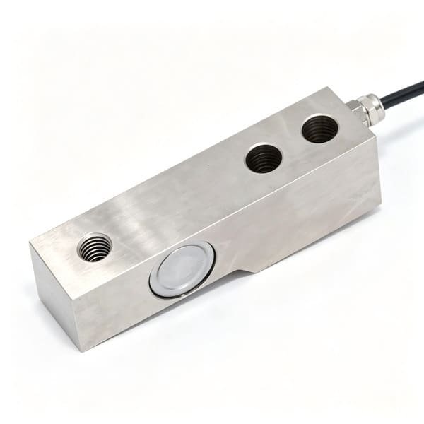
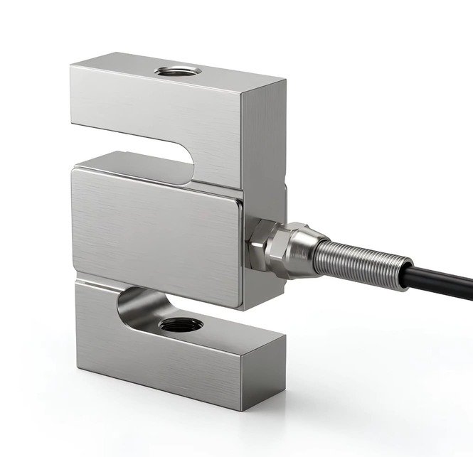

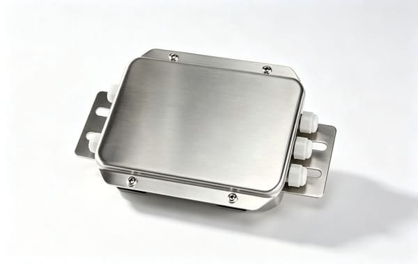

If you are building the truck side rather than the plate side, two further references are worth your time: our notes on load cells for lifting platforms, which covers the same safety-factor reasoning for a different machine, and the OEM integration guide for smart warehouse systems, which is where most forklift weight data ends up. If your application is a mobile machine on a different chassis, our feed mixer wagon and tank weighing notes both deal with the same transfer-error and vibration questions in more detail.
Send me the data plate photo, the carriage class and your worst-case load centre. I will come back with the cell sizing, the derated capacity arithmetic and the channel plan — and an honest answer about whether you need a load cell at all.
Request a specification →
Or email Robin directly