

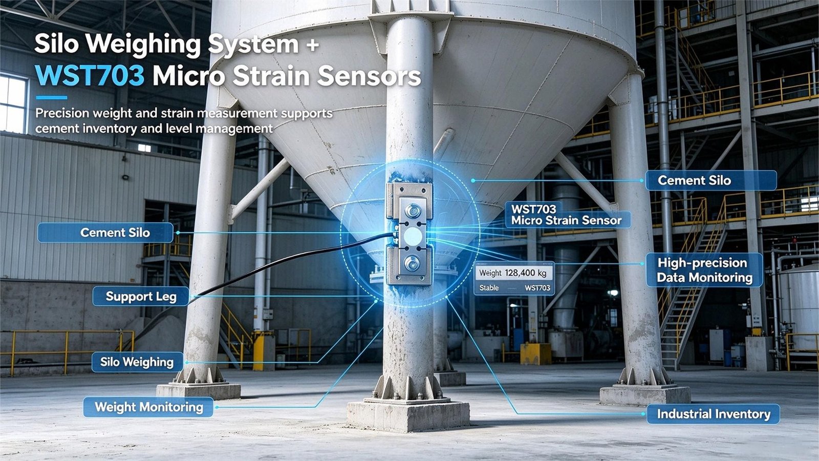
Silo · Tank · Hopper Content Monitoring
Bolt-on strain sensing that turns support legs into a scale
Bolt-on micro strain sensors turn your existing silo, tank or hopper into a weighing system — no lifting the vessel, no emptying it, no foundation work. Built for content, inventory and refill monitoring where a full weigh module installation is more than the job needs.
A WST703 micro strain sensor — product appearance
B Installed on the silo support leg — detail A shown above
Silo weighing built around the vessel you already own
The WST703 is a weldable micro strain sensor — a foil strain-gauge transducer that bolts onto a small mounting pad welded to the support legs of an existing silo, tank or hopper. Once fitted, the vessel structure itself becomes the load-bearing element of a weighing system, so you get a continuous reading of contents in kilograms without installing load cells under the legs, without emptying the vessel and without touching the foundation.
Best suited to
- Leg-supported silos, tanks, hoppers, bins and bunkers
- Inventory and stock-level monitoring by weight
- Refill triggering and overfill protection
- Batching and production process monitoring
- Retrofits where the vessel cannot be taken out of service
Typical system
- 3 or 4 WST703 sensors — one per support leg
- Mounting pads and dedicated bolts, supplied with each sensor
- Summing junction box
- Weighing indicator with set-point relays
- Analogue output or RS485 Modbus to PLC / SCADA
- Calibration by empty-to-full cycle after installation
Not intended for
- Custody transfer or trade settlement
- Invoicing or any legally binding measurement
- Applications requiring OIML R76 / NTEP approval
- Closed-loop dosing where better than 1 % of full scale is specified
If you need trade-grade figures, our compression and shear-beam load cells are the correct choice — see the comparison below.
WST703 specifications
Values below apply to the sensor itself unless the row states otherwise. System-level accuracy depends on the stiffness and symmetry of your support structure.
| Model | WST703 weldable micro strain sensor (bolt-on strain transducer) |
|---|---|
| Measuring principle | Four foil strain gauges bonded in a full Wheatstone bridge, measuring surface strain in the loaded member |
| Rated load (measuring range) | 300 – 1000 με (microstrain). Rated in strain, not in tonnes — the load a leg carries at that strain is set by the section of the leg, and we calculate it from your drawing. |
| Comprehensive precision | 1 – 2 % F.S |
| System accuracy (4 gauged legs) | ±1 – 3 % of full scale, depending on the stiffness and symmetry of the support structure |
| Sensitivity (rated output) | 1.0 – 2.0 mV/V |
| Zero output | ±1 % F.S |
| Input resistance | 380 ± 30 Ω |
| Output resistance | 350 ± 5 Ω |
| Insulation resistance | > 5000 MΩ |
| Recommended excitation | 10 V DC |
| Safe load limit | 150 % F.S |
| Creep (30 min) | ±0.05 % F.S / 30 min |
| Temperature effect on zero | ±0.1 % F.S / 10 °C |
| Temperature effect on output | ±0.1 % F.S / 10 °C |
| Operating temperature | −20 °C to +65 °C, temperature compensated |
| Body material | Alloy steel / stainless steel (for standard and corrosive environments) |
| Protection rating | IP65 — dust-tight and water-jet resistant for outdoor and harsh industrial environments |
| Wiring | 4-wire shielded cable |
| Wiring code | Red = excitation + · Black = excitation − · Green = signal + · White = signal − |
| Mounting | Weld-on / bolt-on. A mounting pad is welded to the load-bearing member (silo support leg, equipment frame or girder) and the sensor body is bolted onto it. No cutting, drilling or structural modification. |
| Installation formats | Multiple formats available to match different structure geometries — tell us the member you are instrumenting and we will specify the correct one |
| On-site calibration | Required after installation, by empty-to-full cycle against a known reference. Written procedure supplied; repeat annually. |
Specifying from a tender document? A typical clause reads: “Vessel mass shall be measured by a non-penetrating, leg-mounted strain gauge weighing system. Four-arm full-bridge foil gauges shall be fitted to the outer surface of each support leg, oriented along the primary bending axis. System accuracy shall be within ±1–3 % of full scale over the operating temperature range. Calibration shall be performed by an empty-to-full cycle with a documented reference weight, repeated annually.” — We can supply the sensor set against this wording; ask us to review your clause before you place the order.
How the measuring range works: 300 to 1000 με
This is the single most misunderstood line on the datasheet, and it is worth two minutes of your time before you specify anything.
The WST703 is rated in microstrain (με), not in tonnes. One microstrain is a change in length of one part per million — 300 με is a one-metre member shortening by 0.3 mm. It describes the deformation the sensor can measure, not the weight it can carry, because the sensor does not carry the load: it reads the deformation of the member that does.
The practical consequence is simple. The same sensor on a slender leg reads a large strain; on a heavy leg it reads a small one. So the question is never “what is the sensor rated at” but “how much does my leg deform when the silo is full”.
The sizing test. Take the axial force in one leg at full contents, divide by the leg’s cross-sectional area, and you have the stress. In steel, a stress between 63 and 210 MPa corresponds exactly to the 300–1000 με window. Land inside it and the sensor is correctly sized. Below it the signal gets small against electrical noise; above it you are outside the rated range and need a different measuring point or a stiffer leg.
What common support sections carry at each end of the range
Indicative only, for first-pass estimating. Assumes axial compression, uniform load sharing between identical legs and E = 210 GPa. It excludes wind and seismic load, eccentric loading, initial bow and welding residual stress.
| Support leg section | Section area | Force per leg at 300 με | Force per leg at 1000 με |
|---|---|---|---|
| Square tube 100 × 100 × 5 | 1,900 mm² | 119.7 kN (12.2 t) | 399 kN (40.7 t) |
| Square tube 120 × 120 × 6 | 2,736 mm² | 172.4 kN (17.6 t) | 575 kN (58.6 t) |
| Square tube 150 × 150 × 6 | 3,456 mm² | 217.7 kN (22.2 t) | 726 kN (74.0 t) |
| Square tube 200 × 200 × 8 | 6,144 mm² | 387.1 kN (39.5 t) | 1,290 kN (131.6 t) |
| Round pipe Ø168.3 × 7.1 | 3,596 mm² | 226.5 kN (23.1 t) | 755 kN (77.0 t) |
| Round pipe Ø219.1 × 8.0 | 5,306 mm² | 334.2 kN (34.1 t) | 1,114 kN (113.6 t) |
| Angle L100 × 100 × 10 | 1,920 mm² | 121.0 kN (12.3 t) | 403 kN (41.1 t) |
| Channel C200 × 75 × 9 | 2,890 mm² | 182.1 kN (18.6 t) | 607 kN (61.9 t) |
You do not have to work any of this out yourself. Send us the section and material of your support legs, or a drawing, together with the empty and full weight of the vessel. Our engineers run the calculation and come back with a model selection and a quotation within 12 hours.
What it actually costs to retrofit weigh modules
A conventional load-cell installation delivers excellent accuracy, but the engineering work around it is what drives the real cost on an existing vessel.
The strain-sensor route inverts that equation. Because the sensor is fitted to the outside of a leg that already carries the load, there is nothing to lift, nothing to empty and nothing to rebuild. Installation is measured in hours rather than days, and because the sensor is an external, replaceable part, a damaged unit is swapped without taking the vessel out of service.
The same advantage shows up in the delivered cost: no civil works, no lifting equipment, no lost production. Send us your vessel details and we will quantify the difference for your specific case.
How a micro strain sensor measures silo contents
Three physical steps, no penetration of the vessel wall and no interruption of the material flow.
1. The leg deforms
Every kilogram added to the vessel passes down through the support legs, compressing them by a few micro-metres. The deformation is proportional to load and is largest at the point of maximum bending moment.
2. The bridge converts it
Four foil gauges are bonded to the sensor element and wired as a full Wheatstone bridge. As the sensor follows the leg’s deformation, its resistance changes by a defined amount and produces a millivolt output of 1.0 to 2.0 mV/V.
3. The indicator reads weight
The indicator sums the signals from all legs, applies the calibration curve established from an empty-to-full cycle, and displays content weight in kilograms — with relay, analogue or Modbus output for your PLC.
Why the reading reacts to the vessel, not just the material. A strain sensor measures deformation of the support structure rather than direct force. That is what makes it cheap and non-intrusive, and it is also why the quality of your leg design matters: a stiff, symmetric, well-braced leg layout gives a more stable reading than a slender or asymmetrically loaded one. We will review your leg drawing before quoting.
Where silo and tank weighing with strain sensors fits
Wherever you need to know how much is in a vessel, and the vessel is supported on legs.
Cement & aggregate storage
Continuous cement silo weighing for stock control and delivery scheduling. Prevents overfilling that damages dedusting filter cartridges.
Concrete batching plants
Aggregate and cement silo content monitoring for batch planning; a check reading alongside existing batching weigh hoppers.
Powder & granulate tanks
Plastics, chemicals, minerals and lime. Works where dust and build-up defeat ultrasonic and radar level devices.
Feed mills & grain storage
Grain, flour, pellets and meal. Weight-based stock figures instead of level percentage estimates.
Weigh hoppers & bins
Retrofit content monitoring on hoppers and bins that were never built with load cells in mind.
Liquid & liquefied vessels
Leg-supported process tanks where a full weigh module installation is not justified by the value of the product.
The same sensor has three other duties
Silo weighing is one application of a general-purpose strain transducer. The identical body, measuring range and bridge output are used for:
Heavy equipment monitoring
Load and overload monitoring on cranes, presses and mining machinery, with reliable peak-value capture in dynamic conditions.
Structural health monitoring
Long-term stress monitoring of bridges, buildings, towers and steel structures — outdoors, with IP65 protection and temperature compensation.
Pressure & force monitoring
Indirect force measurement at points where a traditional load cell physically cannot be installed.
Installation: no downtime, no hot work on the vessel
A four-leg silo is normally fitted within a single working day, depending on site access. The vessel stays in production throughout — only the calibration cycle needs a controlled empty or known-fill condition.
Prepare and locate the mounting face
Grind the outer face of each support leg at the measured position and degrease it with solvent until it is free of rust, oil and burrs. All gauged legs must sit on a load path that is not shared with an adjacent vessel.
Weld the mounting pad
A small steel pad is positioned with the supplied welding jig and welded to the leg face. The sensor is not fitted yet — this is deliberate, so that welding heat cannot reach the strain gauges.
Bolt the sensor to the pad
Retaining compound is applied to the pad and sensor faces, and the two dedicated high-tensile bolts supplied with the sensor are tightened alternately, in two passes: 20 N·m first, then 40 ± 2 N·m. The bolt positions are then marked, so a loosened bolt is visible at a glance during routine inspection.
Wire to the junction box
Run the 4-wire shielded cables to a single summing junction box. The box combines the individual bridge signals into one summed output and provides a convenient point for future sensor replacement.
Calibrate and connect to control
Calibrate with an empty-to-full cycle against a documented reference weight and record the ambient temperature. Configure set points for refill and overfill, or pass the weight to your PLC over analogue output or RS485 Modbus. Repeat the reference check annually.
Why the sensor is bolted and not welded in place. Keeping the sensor as a bolted-on external part has two consequences that matter to you: the vessel is never modified beyond an external pad, and a damaged sensor is replaced with a spanner — no hot work, no lifting, no production stop. It is also why the product is known generally in this industry as a bolt-on strain sensor, and why we supply the mounting bolts with every unit: substitute bolts change the preload, and bolt preload is part of the measurement.
On-site calibration is not optional. The mV output of the sensor depends on the section, material and orientation of the leg it is fitted to, so the system must be calibrated on site after installation. We supply a written installation and calibration procedure with every order and support commissioning by remote guidance. Please plan for one fill cycle to complete it.
Strain sensor vs conventional weigh module: an honest comparison
Neither option wins on every line. The right answer depends on what you are going to do with the number.
| Criterion | WST703 micro strain sensor | Conventional load cell / weigh module |
|---|---|---|
| Installation | Weld a pad on the existing leg, bolt the sensor on; vessel stays in service | Lift vessel onto cells; jacking plan required |
| Vessel must be emptied | No | Usually yes |
| Foundation work | None | Often required |
| Modification of the vessel | An external pad on the leg face only — no cutting, drilling or penetration | Legs and foundation reworked to accept mounting plates |
| Downtime per vessel | Fitted within a working day, in service throughout | 1–3 days |
| Installed cost for 4 points | Substantially lower — no civil works, no lifting, no production stop (send us your vessel details and we will quantify it) | Higher; plus mounting hardware, civil works and downtime |
| Sensor precision | 1–2 % F.S comprehensive | ±0.02–0.05 % FS |
| System accuracy | ±1–3 % FS with four gauged legs | ±0.02–0.05 % FS |
| Custody transfer / trade | Not suitable | Yes, with OIML R76 / NTEP approval |
| Sensitivity to support structure | High — the leg is the measuring element | Low — independent of structure |
| Sensitivity to sun and weather | Some; a solar-heated leg face shifts readings by 1–2 % between sun and shade | Minimal |
| Sensor replacement | Single sensor swapped externally, vessel stays in production | Requires lifting the vessel at that point |
| Best for | Inventory, refill triggering, process monitoring, retrofit | Trade, dosing, compliance-driven measurement |
When you should not choose this sensor
- You invoice, buy or sell material by weight — specify an approved load cell system instead.
- Your silo legs are slender, inadequately braced, or share a load path with an adjacent vessel.
- You need better than 1 % of full scale for closed-loop dosing.
- The vessel is skirt-supported with no accessible vertical leg face.
Saying this plainly is deliberate. We would rather quote you the correct product — or tell you that this one is wrong for your application — than place a sensor you will be unhappy with after installation.
A complete silo weighing system
What we supply
- WST703 sensors — one per support leg, selected against your leg section and strain window
- Mounting pads and dedicated bolts — supplied with each sensor, so the preload is correct
- Summing junction box — combines and trims the individual bridge signals
- Weighing indicator — weight display, set-point relays, analogue or RS485 Modbus output (optional; specified with your enquiry)
- Installation and calibration procedure — written document with every order, plus remote support during commissioning
What it connects to
- PLC and SCADA via RS485 Modbus or 4–20 mA
- Refill and overfill alarms via indicator relay outputs
- Plant-level inventory or ERP systems, where the PLC already forwards weight data
- An existing weighing indicator, where one is already installed on site
Note on resistance: multiple sensors are summed in parallel, so the combined bridge resistance falls with each sensor added. Tell us how many legs you are instrumenting and we will confirm the indicator can drive the load.
Quality, testing and documentation
Manufacturing
Produced under an ISO 9001 quality management system, with incoming material verification, in-process inspection at each assembly station and final test before packing.
100 % inspected before shipment
Every sensor is individually tested before dispatch and shipped with its own test record, so you can verify the unit against your own reference instrumentation on arrival.
Third-party inspection
Inspection by SGS, Intertek or a buyer-appointed agency can be arranged before shipment. Tell us your inspection requirement when you request the quote.
Please note on compliance: the WST703 is a weighing system component, not a certified trade-measurement instrument, and it is not offered against OIML R76 or NTEP type approval. Where your project requires legally approved weighing, we will point you to the appropriate load cell range rather than supply a component that cannot meet the requirement.
Reference configuration: four-leg outdoor cement silo
A typical specification we are asked to quote. Use it as a template for your own enquiry.
Vessel and duty
- Vessel: four-leg cement storage silo, outdoor installation
- Material: ordinary Portland cement, bulk
- Requirement: continuous content reading by weight, plus refill and overfill alarms
- Constraint: vessel must stay in service — no emptying, no lifting, no foundation work
What that specifies
- Four WST703 sensors, one per support leg, plus mounting pads and bolts
- One summing junction box
- One weighing indicator with two relay outputs and RS485 Modbus to the plant PLC
- Stainless steel bodies, for an outdoor installation
Installation sequence
- Pads welded to the leg faces during a planned maintenance window; vessel not emptied
- Sensors bolted on and wired back to the junction box
- Calibration by empty-to-full cycle against a documented reference weight
- Refill and overfill set points wired into the site alarm panel
What the site ends up with
- A continuous cement stock figure available to the supervisor at any time
- Refill triggered before the silo runs low, overfill stopped before the filter is loaded
- No production downtime required for the installation
- A single sensor replaceable in minutes if one is ever damaged
If your vessel looks like this one, send us the leg section and the empty and full weight and we will come back with a firm selection and price within 12 hours.
Frequently asked questions
Questions buyers ask us before quoting, grouped by the stage of the purchase decision.
Finding the right solution
What does the WST703 micro strain sensor measure?
It measures the micro-strain in your silo support leg caused by the weight of the vessel and its contents. Four foil strain gauges bonded in a full Wheatstone bridge convert that deformation into a millivolt signal proportional to load, which the weighing indicator converts into kilograms. In effect it turns an existing leg-supported vessel into a weighing system without installing load cells underneath it.
Which vessels and materials can it be used with?
Any leg-supported or skirt-supported vessel that has a measurable vertical load path in its support structure. Typical applications are cement and aggregate silos, powder and granulate storage tanks, weigh hoppers, bins and bunkers. Handled materials include cement, sand, aggregates, flour, grain, feed pellets, minerals, chemicals and plastics. Outdoor and indoor installations are both supported.
Can the same sensor be used for heavy equipment or structural monitoring?
Yes. The WST703 is a general-purpose weldable strain transducer, and silo weighing is one of four duties it is built for. Beyond silo, tank and hopper weighing it is used for load and overload monitoring on cranes, presses and mining machinery, for long-term stress monitoring of bridges, buildings, towers and steel structures, and for indirect force measurement where a traditional load cell cannot physically be installed. The same body, the same 300 to 1000 microstrain range and the same 1.0 to 2.0 mV per volt output apply to all of these duties.
Matching it to your site
Do I need to empty the silo or lift the vessel to install it?
No. Because the sensors are fitted to the outside of the existing support legs, the vessel does not have to be lifted onto load cells, emptied, or removed from service. No foundation modification is required, and the vessel is not cut or drilled — only a small external mounting pad is welded to each leg face. A four-leg silo is normally fitted within a single working day, depending on site access, and calibration is done afterwards with an empty-to-full cycle.
Is the sensor welded or bolted to the support leg?
Both, in sequence. A small steel mounting pad is welded to the outer face of the support leg, and the sensor body is then bolted onto that pad with two dedicated high-tensile bolts supplied with the sensor. This is why the product is known in the industry as a bolt-on strain sensor. The vessel itself is never cut, drilled or otherwise modified, and because the sensor is bolted rather than welded in place, a damaged unit can be replaced in minutes without any hot work on the structure.
How many sensors do I need for my silo?
One sensor per support leg. A three-leg silo uses three sensors, a four-leg silo uses four. Gauging all legs is strongly recommended, because measuring only half of the legs makes accuracy dependent on how evenly the material is distributed inside the vessel. All sensors connect to a single summing junction box and one weighing indicator.
Can it connect to my PLC or existing indicator?
The sensor itself is a passive strain-gauge bridge rated at 1.0 to 2.0 mV per volt, with an input resistance of 380 ohm plus or minus 30 ohm and an output resistance of 350 ohm plus or minus 5 ohm, so it works with standard weighing indicators, strain-gauge transmitters and DAQ systems. Recommended excitation is 10 V DC. With a suitable indicator you can get relay set points for refill or overfill alarms, plus analogue output or RS485 Modbus for connection to a PLC or SCADA system.
What mounting formats are available?
Several installation formats are available to match different structure geometries, because a silo leg, a lattice member and a machine frame do not present the same mounting face. The sensor can be welded-on or bolt-on, and the mounting pad is selected to suit the surface it is fixed to. Send us a drawing or a photograph of the member you intend to instrument and we will specify the correct format with your quotation.
Comparing with other options
How accurate is a strain-based silo weighing system compared with traditional weigh modules?
The sensor itself is specified at 1 to 2 percent of full scale comprehensive precision; built into a system with four gauged legs it typically achieves plus or minus 1 to 3 percent of full scale, depending on how stiff and symmetric the support structure is. A calibrated compression or shear-beam load cell achieves roughly plus or minus 0.02 to 0.05 percent of full scale. The gap is a property of the measuring principle: a strain sensor measures leg deformation rather than the direct force passing through a cell, so it remains sensitive to the stiffness and symmetry of the support structure.
When should I choose a strain sensor instead of a load cell?
Choose strain sensors when you need continuous content or inventory monitoring and refill triggering, when the vessel cannot easily be lifted or emptied, and when installed cost matters more than measurement uncertainty. Choose load cells when you need trade-grade accuracy, custody transfer, or legally verifiable weighing. The two approaches solve different problems and are frequently combined on the same site.
Can I retrofit it onto a silo that already has weigh modules?
Yes, and this is one of the most common use cases. Strain sensors are also used as a cheap secondary check on an existing weighing installation, and as a fast replacement for individual weigh modules that have failed or been damaged, since a single sensor can be swapped without taking the vessel out of production.
Verifying and de-risking
Can the system be used for trade settlement or custody transfer?
No, and you should not specify it for that purpose. Applications such as invoicing, buying and selling by weight, or any legally binding measurement require a certified load cell system approved to OIML R76 or the equivalent national regulation. The WST703 is intended for internal inventory control, production monitoring and refill triggering, where a plus or minus 1 to 3 percent indication of contents is sufficient.
Does the system need on-site calibration?
Yes, and you should plan for it. Because the output depends on the section, material and orientation of the leg it is fitted to, the system must be calibrated on site after installation using an empty-to-full cycle against a known reference weight or a documented fill quantity. The calibration takes one fill cycle to establish and is normally repeated annually. We supply a written calibration and installation procedure with every order, and our engineers support the commissioning by remote guidance.
What about temperature drift, creep and long-term stability?
The sensor is temperature compensated from minus 20 to plus 65 degrees C, with a temperature effect on zero and on output of plus or minus 0.1 percent of full scale per 10 degrees C, and creep of plus or minus 0.05 percent of full scale per 30 minutes. Residual effects come mainly from the vessel itself: steel with a solar-heated outer face can shift the reading by one to two percent between sun and shade, and powder settles and compacts after a fill event, which can change the apparent mass by a few percent over several hours. A digital low-pass filter with a 60 to 120 second time constant removes both the settling effect and most mechanical vibration.
What documentation and testing comes with the shipment?
Sensors are manufactured under an ISO 9001 quality management system and 100 percent inspected before shipment. Each unit is supplied with its own test record so you can verify it against your own reference. Third-party inspection by SGS, Intertek or a buyer-appointed agency can be arranged on request — tell us your inspection requirement when you request the quote.
How do I know the 300 to 1000 microstrain range matches my silo?
The sensor is rated in microstrain, not in tonnes, so the question is not how heavy your silo is but how much the leg deforms under that load. Work out the axial stress in one leg, force divided by cross-sectional area, and it should land between about 63 and 210 megapascals, which corresponds to 300 and 1000 microstrain in steel. Below that window the signal becomes small against noise; above it you are outside the rated range. Send us the section and material of your support legs with the empty and full load per leg and our engineers will confirm the fit within 12 hours.
Preparing your request
What information do I need to provide to get an accurate quote?
Please confirm six items: vessel type and support arrangement with a drawing if available, number of support legs, the estimated load per leg with the vessel empty and full — or simply the section and material of the legs, and we will calculate the strain for you — the material being handled, indoor or outdoor location with the ambient temperature range, and the required output or control interface. With those details we return a quotation and a model selection within 12 hours.
What are the MOQ, lead time and payment terms?
Trial orders are welcome, so you can start with the quantity needed for a single vessel before scaling to a plant-wide rollout. Lead time is quoted against the confirmed specification and quantity at the time of quotation. Standard export payment terms are available and can be discussed with the quotation.
Tell us about your vessel — we will quote within 12 hours
Send the six details on the right, or a drawing and a target budget, and we will come back with a model selection, a quantity and a delivered price. Trial orders are welcome.
What to send us
- Vessel type and support arrangement (drawing or photo)
- Number of support legs
- Load per leg (empty and full) — or simply the leg section and material, and we will calculate the strain
- Material handled and its bulk density
- Indoor or outdoor, ambient temperature range
- Required output: indicator only, relay, 4–20 mA or RS485 Modbus
