
Wireless Dynamometers: Crane Scales, Load Links and Shackle Pins — Field Notes From Real Lifting Jobs
📅 October 5, 2026
⏱️ 16 min read
🏗️ Lifting & Load Testing
A wireless dynamometer is a promise: hang this under the hook and it will tell you the truth about the load. Most of the time it does. The times it doesn’t are almost never the sensor. They are the channel plan, the pin that didn’t match the shackle, the battery nobody changed, or a reading someone took while the load was still swinging. What follows is what I have learned about the practical design, selection and failure of wireless dynamometers — crane scales, tension load links and instrumented shackle pins — and why the most interesting problem I solved last year was a commercial one, not an electrical one.
I’m Robin from VektorForce. We supply load cells, force sensors, wireless dynamometer links, junction boxes, transmitters and indicators — the weighing core. We are not a crane manufacturer and we do not issue the lifting certificate.
1. Why a wireless dynamometer is a trust problem, not a hardware problem
The category is growing for a reason that has nothing to do with sensors. Wireless crane scales and load monitoring systems are being pulled into ordinary lifting work because the alternative — a wired load pin, a strain gauge, a hydraulic load cell with a pressure gauge — asks a rigging crew to become instrument technicians. A wireless dynamometer asks them to charge a battery and press ZERO.
The numbers support the shift. One market study sizes the wireless crane scale market at $846.3 million in 2025, growing to $1.26 billion by 2032 (5.9% CAGR), with load-cell-based designs taking roughly half of segment revenue. The broader wireless load monitoring system market is projected at $1.91 billion in 2026 rising to $4.82 billion by 2032 — a 16.24% CAGR, because the growth is not in new hardware categories but in connecting existing lifting operations to data. The category is led by long-established names — Straightpoint, Crosby, Eilon Engineering, Dini Argeo and others — plus a long tail of Chinese and Indian manufacturers, which is exactly why the differentiator is no longer the load cell. It is the whole chain behind the number.
The short version, if you only read one paragraph:
- Choose the form factor first (crane scale vs in-line load link vs shackle pin) — it decides headroom, rigging interface and whether the job is even possible.
- Accuracy is quoted against full scale, not against your reading. A 0.05% FS cell used at one-tenth of its range is a 0.5% instrument.
- The three links that fail in the field are the wireless channel plan, the pin-to-shackle fit, and battery discipline — in that order.
- We build the transducer and the weighing electronics. The certified lifting system and the crane certificate belong to the integrator and the independent inspection body.
Everything below is written from the supply side of the table. I sit between a customer’s lifting problem and a factory in China, and I spend most of my time translating between the two. For the record: we are a weighing-component exporter. When I say “we” below, I mean load cells, force sensors, wireless dynamometers, junction boxes, transmitters and indicators — nothing with a hook block on it.
2. Crane scale, load link, or shackle pin? Pick the form factor first
Almost every “which dynamometer should I buy” question is really a geometry question. The three common form factors measure the same physical quantity — in-line tension — but they occupy completely different amounts of space in the load path, and that decides the job.
| Form factor | How it works | Typical range | Where it wins | What bites you |
|---|---|---|---|---|
| Crane scale (dynamometer body) | A cell with an integral hook or eye; display on the body, a handheld, or both | 1–200 t | General lifting, foundries, yards, ports, rental fleets | Consumes headroom; the body display is unreadable from the ground |
| Load link (tension link) | A closed loop pinned between two shackles, directly in the line of pull | 5–200 t | Bollard pull, proof and water-bag testing, in-line tension anywhere | Pin and bore mismatch, lateral load, wrong shackle pairing |
| Shackle pin load cell | An instrumented pin that replaces the shackle’s own pin | 20–500 t | Minimal headroom, permanent rigging points, offshore and marine | The pin must match the actual bore; side-load sensitivity |
| Multi-channel set | Several bodies reporting to one indicator, displayed and summed | 1–200 t per body | Asymmetric multi-point lifts, spreaders, gantry synchronisation | Channel discipline; summing assumes the geometry you think you have |
The same question looks different in every market I sell into. An Italian marble quarry moving 25-tonne blocks on an overhead bridge crane wants a load link in the hoist line, because the block is slung and the headroom is fixed. A Brazilian granite yard handling slabs wants the same thing with a different rigging interface. A crane rental fleet in the Gulf running 25–700 tonne mobile cranes wants load links and pins for proof testing and lift planning across a mixed fleet. A copper mine in northern Chile wants a reference instrument that a third-party inspector can hang under an overhead crane during a periodic load test. Aberdeen and the North Sea want load shackles and running-line monitors for subsea and decommissioning work. Four markets, four interfaces, one measurement.
3. The four things that actually decide a reading
Datasheets list dozens of parameters. In practice, four of them decide whether the number on the display is believable.
1. The wireless link. A 2.4 GHz link is the default because it is licence-free and cheap, and 433 MHz and 868 MHz are the options where the band is congested or the path is long. A typical industrial dynamometer gives you a nominal working range of about 80 m in the default configuration, extendable to roughly 200 m. On a steel-heavy site that number is optimistic: the same 2.4 GHz signal that reaches 80 m across a yard may manage 15 m through a container stack. If the operator stands behind a blast wall or inside a control cabin, the band and the range stop being a spec and start being the whole project.
2. Battery discipline. The conventional crane scale runs for around 50 hours on three or four AA alkaline cells. A well-designed instrumented pin can run for more than 100 hours on a single 18650 lithium cell. Either number is generous — right up to the point where someone leaves the unit switched on in a site office for three weeks. A low transmitter battery does not shut the system down politely; it degrades the link and produces a reading that looks like a load. Every “the scale lied” complaint I have investigated started with a battery.
3. Sealing. IP66 is the floor for outdoor and marine use and IP67 is what you want where the unit gets hosed down or briefly submerged. The subtlety is that the sealed body is rarely the failure point. Water gets in through the connector, or condenses inside the enclosure when a warm unit is brought into a cold night and the electronics cool below dew point. Micro-condensation degrades a strain-gauge circuit slowly and invisibly, and it shows up as drift months later, not as a dead unit on day one.
4. Zero stability. Every instrument has a power-on zero range (typically 20% of full scale) and a manual zero range (typically 4%), plus a tare range for slinging gear. That is enough to cancel a shackle and a sling. It is not enough to hide a load cell that has been over-ranged. A single event at 300% of capacity can leave a permanent offset that no amount of ZERO will fix, and the honest way to catch it is a periodic calibration check against a known load, not more button-pressing.
Two field habits that prevent most bad readings:
- Read after the load stops moving. A typical stabilisation time is five seconds or less, but that only counts from the moment the load is stationary. A reading taken during sway is not an average — it is a sample of a pendulum, and it will be wrong in whichever direction the load happened to be travelling.
- Zero with the rigging attached, not before. Hook on the shackle, slings and any spreader, then zero. If you zero bare and tare later, every operator will do it slightly differently and your records will not be comparable.
4. Case 1: the distributor who wanted any indicator to talk to any cell
This is the most interesting project of the last year, and the sensor was working perfectly the whole time.
One of our overseas distributors sells electronic weighing instruments — bench scales, indicators, spares — into local industry. They wanted to add a wireless dynamometer to their range, and they raised a commercial problem before a technical one. The dynamometer we were quoting shipped, as most do, as a matched pair: one instrument body bound to one handheld indicator, factory-paired, one-to-one. For a distributor that is a stocking problem. A customer who wants to save money buys the body only. Months later the same customer decides they would like to see the numbers and asks for an indicator — and now the distributor either ships a specific matched unit from a specific batch or tells the customer the body they already own is incompatible. Neither answer sells a second unit.
Their request was precise: make the handheld indicators interchangeable with the dynamometer bodies, so that any indicator can send to and receive from any body. Reduce the number of matched combinations to one.
The result was a distributor-side inventory change, not a metrology change. They could stock bodies and indicators as two separate lines, and a customer who bought a body first could add any indicator later. That is the kind of request that never appears on a datasheet, and it is exactly the kind of request that decides whether a range sells in a given market. It is also a reminder of where the value in this category actually sits: the transducer is a commodity, and the commercial flexibility built around it is not.
If you are a distributor reading this, the question to ask any dynamometer supplier is not “what is your accuracy?” It is “can your indicators be swapped between bodies, and can your bodies be swapped between indicators, without me managing matched pairs?”
5. Case 2: the water-bag proof load in Antofagasta
The second project is about the environment a dynamometer has to survive, and it comes from the mining world.
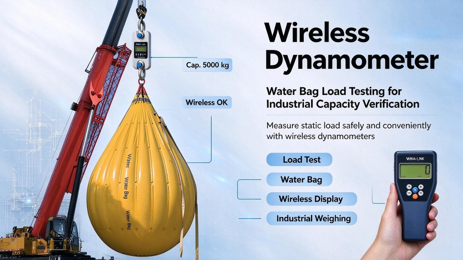
Antofagasta, in northern Chile, is copper country, and the lifting equipment there is certified on a strict cycle. An independent inspection body — one that, by the local rulebook, may not also sell or repair the lifting gear it inspects — periodically proof-loads overhead cranes, hoists and mobile cranes using water bags as the test load. The regulatory logic is universal even where the statutes differ. In North America the reference for below-the-hook devices is ASME B30.20, alongside the wider ASME B30 series for cranes, hoists and rigging; in Chile the inspection bodies work to INN 17020 for independence, plus the mining and workplace safety regulations that mandate documented load testing and kept maintenance records. Whichever rulebook applies, the practical requirement is the same: a hoist, bridge crane or mobile crane must be load-tested for safe-use certification on a recurring basis — at least annually, and every six months for some equipment — while the hook and structural members also pass non-destructive examination with beam deflection measured and recorded.
The instrument that turns that test from a visual judgement into a number is a dynamometer in the load path. In early 2026 we shipped wireless tension load links into that workflow, and three practical problems came back — all of them instructive.
That last point quietly settles a question customers ask me constantly: “is your dynamometer calibrated?” The useful answer separates three different documents — the instrument calibration (ours, or a lab’s, traceable to a mass standard), the load-test report (the inspection body’s, covering the crane), and the lifting system certificate (the integrator’s or end user’s, covering the assembly). A datasheet accuracy figure is none of these three.
6. Accuracy: what “0.05% FS” really buys you
Nearly every wireless dynamometer in this class quotes the same two figures: 0.05% of full scale for capacities up to about 50 t, and 0.1% above that. Here is what that means in a real lift, and where it quietly stops being true.
The first trap is the letters FS. An accuracy of 0.05% FS is a fraction of the cell’s rated capacity, not of the load you happen to be lifting. Put a 10 t cell on an 800 kg load and the permitted error is 0.05% of 10,000 kg — five kilograms — which is 0.6% of the actual load. The number did not get worse; you moved the load away from the operating point. This is the single most common reason a warehouse complains that “the dynamometer is out by half a percent” while the datasheet says 0.05%.
The second trap is resolution. The displayed increment, or division, is coarser than the accuracy figure at the top of the range, and it sets the floor on what you can see:
| Rated capacity | 1 t | 2–3 t | 5 t | 10 t | 20–30 t | 50 t | 100 t | 200 t |
|---|---|---|---|---|---|---|---|---|
| Display division | 0.5 kg | 1 kg | 2 kg | 5 kg | 10 kg | 20 kg | 50 kg | 100 kg |
Notice what that table implies about choice of capacity. If your heaviest routine lift is 6 t, a 10 t cell gives you a 5 kg division; a 20 t cell gives you 10 kg. Buying one size up “for headroom” costs you real resolution at the load you actually lift every day. The right discipline is to size for the peak, not for the fleet.
The third trap is everything the datasheet leaves out. Accuracy in the catalog is specified in a lab, at a reference temperature, on a centric load. In the field you add:
- Temperature effect. A typical operating window is -20 °C to +50 °C, and zero drift with temperature is a separate specification from accuracy. A cell that is honest at 20 °C is not automatically honest at 0 °C in a winter yard.
- Eccentric and lateral loading. Tension is the only load the number is valid for. Side pull, twist and bending are errors the display cannot tell you about.
- Dynamic amplification. A snatch load or a quick plug lifts the instantaneous reading well above the static weight. This is why capacity headroom exists at all.
- Gravity. The acceleration of gravity varies with latitude and altitude, and a good dynamometer lets you correct for it in the indicator rather than pretending it does not exist. For certification-grade testing in a specific location, set it.
7. Multi-point lifts: why one dynamometer is a blind spot
A single dynamometer under a single hook tells you the total load. It tells you nothing about how that load is shared. On a symmetric two-leg lift with a balanced load that is fine. On a four-point lift of a heavy, uneven fabrication, or a spreader beam with an offset centre of gravity, the total can be perfectly safe while one leg is at 140% of its rating — and the display will not blink.
The answer is multiple dynamometers reporting to one place, and there are two ways to build it. The first is a set of wireless bodies summed by a multi-channel indicator: one of our models displays up to four dynamometers simultaneously and their sum, with two programmable set-points for warning and limit. The second is to bring the individual channels into a junction box and sum the signals before the indicator. Both work; the difference is where the summing happens and whether you keep the individual channels visible.
My bias is towards keeping the individual channels visible wherever the lift is asymmetric, because the sum is the number people watch and the individual channels are the number that saves the lift. A multi-channel display that shows both — four values and the total, updating together — is what actually prevents the rigging failure, not the total on its own.
Two cautions. First, summing assumes geometry: if the indicator adds four channels to get a total, the four channels must be measuring four legs of the same load, and the calibration of each must be consistent. Mix a calibrated unit with an uncalibrated one and the sum is fiction. Second, multi-channel sets are where the channel discipline from Case 1 stops being a convenience and becomes a safety requirement. On a two-crane site, two channels keep two teams from reading each other’s loads.
8. Safety factors, and who owns the certificate
Every dynamometer datasheet carries a small cluster of overload numbers, and they are worth reading properly because they describe the difference between an alarm and a failure.
| Number | Typical value | What it means in practice |
|---|---|---|
| Overload indication | 100% FS + 9 divisions | The display warns you the moment you pass rated capacity — before anything is damaged |
| Maximum safety load | 125% FS | The top of the range the instrument is expected to survive in service |
| Ultimate (breaking) load | 300–400% FS | The mechanical margin before structural failure — not a working range |
| Periodic proof test | 125% of rated capacity (rule of thumb) | The overload an inspection body applies when re-certifying lifting gear |
Read together, those four lines explain a design. The instrument warns at 100%, is expected to live through 125%, and is built so that catastrophic failure does not begin until three or four times rated capacity. The gap between 125% and 400% is not sloppiness — it is the margin that absorbs a shock load, a snatch, or a load cell doing its job while a rigging crew does something it should not.
9. How I spec a wireless dynamometer now
Ten years of quoting has boiled down to ten questions. Answer these in order and the choices mostly make themselves.
| Decision | The question I ask | Why it matters |
|---|---|---|
| Form factor | Scale, load link, or instrumented pin? | Headroom and rigging interface decide feasibility before accuracy does |
| Capacity | Heaviest lift, times 1.5 to 2, rounded up | Covers shock and dynamic amplification without oversizing for comfort |
| Division | What is the smallest change you must see? | Resolution is the practical accuracy at the working load |
| Band | 2.4 GHz, or 433/868 MHz? | Congested Wi-Fi bands versus longer range and better penetration |
| Range | Where does the operator actually stand? | 80 m open air collapses through steel; 200 m optional buys margin |
| Battery | 50 hours on AA, or 100+ on lithium? | Multi-day testing and remote sites cannot stop to swap cells |
| Sealing | IP66 or IP67, and how good is the connector? | Condensation and washdown kill electronics through the connector |
| Interface | Shackle or pin pattern, and measured bore | The joint is the first thing to fail and the last thing people check |
| Records | What calibration document does the auditor want? | Instrument calibration, load-test report and system certificate are three different things |
| Multi-point | How many bodies, and is the load symmetric? | Asymmetric lifts need summed plus individual channels |
10. Where the weighing core ends
I want to be blunt about this, because it saves everybody time. VektorForce makes and exports the weighing core. That means:
✔ What we supply
- Wireless dynamometers: crane scale bodies, tension load links, instrumented shackle pins, multi-channel sets
- Handheld and panel indicators, transmitters and amplifiers
- Junction boxes and summing hardware
- Load cells and force sensors for ODM/OEM integration
- A traceable calibration record per unit
- Selection support: capacity, division, form factor, interface, band
✘ What we do not supply
- Cranes, hoists, spreaders, hooks or rigging hardware
- The certification of a complete lifting system, its SWL marking or ID plate
- Lifting certificates, inspection reports or third-party approval
- Becoming the inspection body — independence rules forbid it
- Site commissioning or statutory inspection services
That division is not a limitation; it is a positioning. If you are an integrator building a certified load monitoring or lifting system, you want a component supplier who will stay in their lane, hit the specification, and hand you the calibration evidence you need to certify your own assembly. If you are a distributor, you want a supplier who will adapt the commercial packaging — like the channel swap in Case 1 — instead of insisting you stock matched pairs. Both of those are easier when the supplier is not also trying to sell you a crane.
11. Recommended wireless dynamometers
Four units cover almost everything I quote in this category: a general-purpose crane scale, a heavy tension load link, a high-capacity instrumented shackle pin, and a multi-channel set for multi-point lifts. Full range also includes the WST902 load link with handheld indicator, the WST904 link with RS-232 and USB logging to PC software, and the WST906 IP67 carbon-steel load pin for 5–30 t work — see the wireless dynamometer range for the whole family.

WST901 — Wireless Dynamometer / Crane Scale
The general-purpose unit. Aluminium below 5 t, alloy steel from 10 t up, powder coated, with 5-digit backlit LCD on the body and on the handheld indicator.
- Capacity: 1–200 t in eleven steps
- Accuracy: 0.05% FS (1–50 t) / 0.1% FS (above 50 t)
- Wireless: 2.4 GHz default (433/868 MHz options); 80 m standard, 200 m optional
- Battery: ≥50 h, 3×AA body + 4×AA indicator
- Overload: indication 100% FS +9e; max safety 125% FS; ultimate 400% FS
- Functions: peak hold, 2 programmable set-points, password-protected calibration, gravity correction, kg/t/lb/N/kN
- Interface: G2130 galvanised shackle bows; RS-232 for printer or scoreboard; carry case
- Environment: -20 to +50 °C, ≤85% RH
Best for: general lifting, foundries, yards, ports and rental fleets — the one to buy when the job is ordinary and the volume is real.

WST903 — Wireless Tension Load Link
A closed-loop link that sits directly in the line of pull with minimal headroom loss — the format the inspection and testing world prefers.
- Capacity: 5, 10, 20, 30, 50, 100, 150, 200 t
- Accuracy: 0.05% FS (1–50 t) / 0.1% FS (above 50 t)
- Material: nickel-plated high-strength alloy steel
- Interface: G2130 industrial anchor shackle bows, galvanised
- Functions: wireless handheld with zero, tare, peak hold, overload warning, 2 set-points, gravity correction, password calibration
- Output: RS-232; carry case included
Best for: port equipment, water-bag and proof-load testing, bollard pull, boat and marine work, and any in-line tension reading where the headroom is fixed by the existing rigging.

WST905 — Wireless Pin Shackle Load Cell
A high-capacity instrumented shackle with an integrated sensor design, built for the loads where headroom is the whole problem.
- Capacity: 20, 30, 50, 100, 200, 500 t
- Accuracy: 0.5% FS (1–50 t) / 1% FS (above 50 t)
- Construction: novel integrated sensor design, ultimate load to 300% FS
- Sealing: professional waterproof design to IP66
- Battery: one 18650 lithium cell, >100 h uninterrupted working
- Control: two self-set load control points for safety alarm and weight control — an exclusive design of ours
- Indicator functions: zero, tare, peak hold, cumulative, cumulative query and clear, unit switch, voltage query
Best for: heavy rigging, offshore and marine lifts, and permanent lifting points where a standard shackle pin is already in the load path. The 100-hour battery matters most in exactly the places where you cannot reach the unit easily.

WST907 — Multi-Channel Wireless Dynamometer
The multi-point answer. One indicator reads up to four dynamometer bodies and their sum at the same time, so an asymmetric lift stops being a blind spot.
- Capacity: 1–200 t per body
- Channels: displays up to 4 dynamometers and the sum simultaneously
- Accuracy: 0.05% FS (1–50 t) / 0.1% FS (above 50 t)
- Wireless: 2.4 GHz default (433/868 MHz options); 80 m standard, 200 m optional
- Battery: ≥50 h, 3×AA body + 4×AA indicator
- Overload: max safety 125% FS; ultimate 400% FS
- Functions: 2 programmable set-points, peak hold, gravity correction, G2130 galvanised shackle bows
Best for: spreader beams, four-point lifts, gantry and tandem-crane synchronisation, and any lift where the total is safe but the distribution is the risk.
12. FAQ
What is a wireless dynamometer, and how is it different from a crane scale?
They are the same family of instrument, used with a slightly different emphasis. A crane scale measures the weight of a suspended load and is usually judged on weight accuracy. A dynamometer measures in-line tension as a force and is used where the number itself — proof load, bollard pull, structural tension — is the purpose. In practice one unit does both: our WST901 is sold as a wireless dynamometer and as a crane scale, with kg, t, lb, N and kN all selectable. If you need weight, buy a scale; if you need force in the load path, buy a dynamometer. If you need both, you need nothing extra.
Is the 0.05% accuracy measured against full scale or against the reading?
Full scale — and that distinction decides whether you are happy with the instrument. 0.05% FS means 0.05% of the rated capacity, whatever load you are lifting. On a 10 t cell that is 5 kg whether you are lifting 10 t or 800 kg. At 800 kg the permitted error is therefore about 0.6% of the reading. The instrument is not lying; it is simply being used far below its design point. Choose the smallest capacity that still covers your peak lift with a 1.5× to 2× margin, and the stated accuracy will match your reality.
How does the wireless link behave on a steel-heavy site?
Worse than the headline number suggests. A 2.4 GHz link is typically specified to about 80 m in open air, extendable to roughly 200 m, and 433 MHz and 868 MHz are the options when the band is congested or the path is long. But radio does not travel through steel structures, and a path that is clear in a drawing can be blocked by a container stack, a crane girder or a blast wall. Tell us where the operator stands and what is between them and the load; if the answer involves steel or a control cabin, we will move you to a lower frequency and a longer range rather than let you discover it on the first lift.
How long do the batteries last, and which chemistry should I choose?
A conventional crane scale or multi-channel body runs roughly 50 hours on three or four AA alkaline cells. Our instrumented shackle pin runs more than 100 hours on a single 18650 lithium cell. Both figures are continuous working time, not standby. Choose AA where you want roadside replaceability and lithium where you want endurance and cannot easily reach the unit. Either way, put the battery in the pre-lift checklist — a weak transmitter battery produces a reading that looks plausible, which is far more dangerous than a dead display.
Can I use your dynamometer as the reference instrument in a periodic load test?
Yes — that is one of the most common uses, and it is why we ship a traceable calibration record with each unit. A wireless tension load link is the natural format, because it drops into the existing rigging with minimal headroom loss. But be clear about the three separate documents involved: the instrument calibration is ours or a lab’s, the load-test report belongs to the independent inspection body that runs the test, and the lifting system certificate belongs to whoever assembles and owns the system. A datasheet accuracy figure is none of those. Many jurisdictions additionally require the inspection body to be independent of the equipment supplier, which is a rule we respect rather than work around.
What capacity and IP rating do I need for outdoor or marine use?
Capacity first: take your heaviest lift, multiply by 1.5 to 2 for shock and dynamic amplification, then round up to the next available range — typically 1, 2, 3, 5, 10, 20, 30, 50, 100 or 200 t, with the pin shackle family extending to 500 t. On the environment, treat IP66 as the minimum for outdoor work and IP67 where the unit is hosed down or might be briefly submerged; our WST905 pin shackle is IP66 with a fully integrated sensor, and the WST906 load pin is IP67. Remember that the connector, not the housing, is usually where water gets in — so ask about the connector’s own sealing, not just the box rating.
Can I sum several dynamometers for a multi-point lift, and will it work with my existing indicator or PLC?
Yes to the first, usually to the second. Our WST907 displays four dynamometer bodies plus their sum on one indicator, with two programmable set-points for warning and limit — that is the cleanest way to keep individual channels and the total visible at once. If you want to bring the channels into your own system, individual links with an RS-232 output or a junction box that sums the bridge signals before your indicator will do it. Two rules: every channel in the sum must be calibrated consistently, and you must know the geometry, because the total is only meaningful if the four channels belong to the same load.
Do you supply the complete certified lifting system?
No, and we are deliberate about it. We supply the wireless dynamometer, load cells, force sensors, indicators, transmitters and junction boxes — the weighing core, with a traceable calibration record behind each unit. The certified lifting system — a marked assembly with a stated safe working load, an ID plate and a release for use — is assembled, marked and certified by the integrator or responsible person who owns it, and the crane and its below-the-hook gear are certified by an independent inspection body. We would rather be excellent at the measurement layer than mediocre across the whole chain.
Send me the lift — I’ll size the dynamometer
Heaviest load, form factor you can fit (scale, load link or pin), headroom available, rigging interface and the environment it works in. That is enough for a capacity recommendation and a drawing. If you already have a shackle or pin pattern, send the dimensions too.
We supply the weighing core: wireless dynamometers, load cells, force sensors, junction boxes, transmitters and indicators — with a traceable calibration record. Trial orders welcome.
Get a dynamometer sized for your lift →
Email Robin directly
VektorForce · Wireless dynamometers, load cells, force sensors, junction boxes, transmitters & indicators · www.vektorforce.com