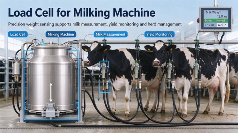

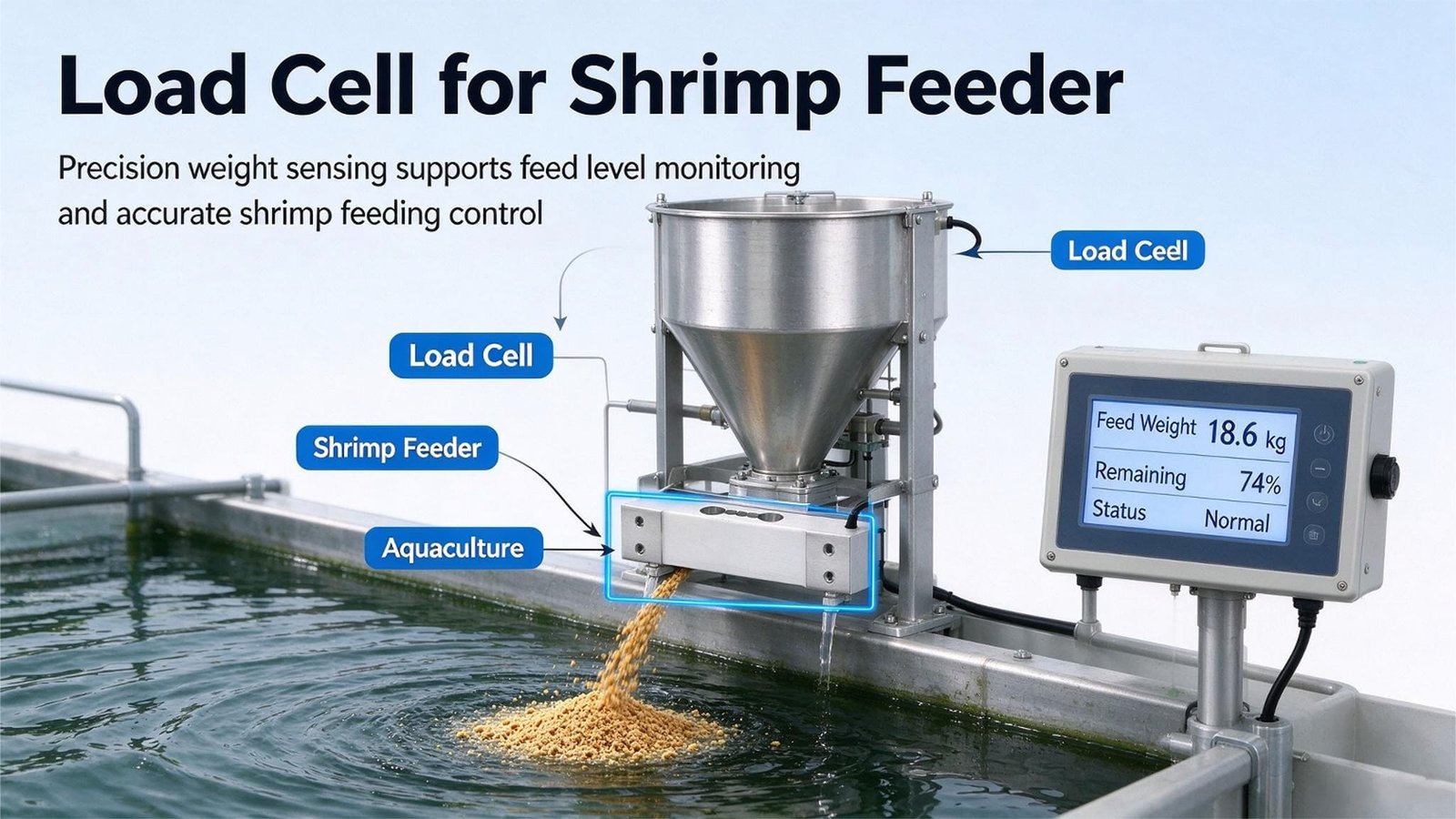
Load Cells for Shrimp Feeders: Why Your Feeder’s Own Feed Log Is Not Evidence
Shrimp feed is a sinking pellet with a bulk density between 0.53 and 0.66 kg per litre — and that number moves with the manufacturing process, not with the recipe. Most automatic feeders still meter it by counting the revolutions of a rotary valve or the duty cycle of a screw. That works beautifully right up to the moment the farm changes pellet size. Here is what I have learned putting load cells under shrimp feeders, on pond banks in Ecuador, Vietnam and Andhra Pradesh.
October 9, 2026
12 min read
WST101 · WST1101 · WST201
I sell load cells, force sensors, junction boxes and weighing indicators to the people who build feeding machines. I do not build the feeding machine. That distinction matters more in aquaculture than anywhere else I work, because on a shrimp farm the feeding machine is doing something no other machine on the site does: it is the only device that knows how much feed left the building.
Which is why it is genuinely uncomfortable to sit in a meeting with a feeder manufacturer and have to say the thing I have now said on three continents: your machine’s feed log is not evidence of anything. It is a record of what your controller asked the valve to do, converted into kilograms using a number you measured once, in your workshop, on one bag of feed.
In shrimp farming that number is not a constant, and it is not even close. It moves by roughly 20–25% between the two manufacturing processes that produce the same pellet. That is not a rounding error. On a 20-tonne-per-year pond it is thousands of dollars, and it lands in the one place the farm cannot defend: the feed conversion ratio it reports to its buyer, its bank, and increasingly to an auditor.
- Why a shrimp feeder is a volumetric machine wearing a weight label
- The two jobs you are asking one hopper to do
- Start from the dose, not the hopper
- What the pond actually asks for: ration tables and the cost of 1%
- Loss-in-weight or gain-in-weight on a pond bank?
- The 550 W thrower standing 40 cm from your load cell
- Transfer error on a wet frame: pipes, mesh and shipping braces
- Density, moisture and fines: why grams-per-pulse drifts
- Case 1 — Ecuador: the 19.6% that nobody could see
- Case 2 — Vietnam: the anti-rat mesh that ate 1.6 kg
- Case 3 — India: the 100 kg load cell that hid its own error
- IP65, IP68, IP69K: where to spend and where not to
- Wiring, transmitters and getting the number into a PLC
- Commissioning and re-verification on a pond bank
- ASC, BAP and CE: what I certify and what I do not
- What I supply and what I do not
- Load cells I would actually put on a shrimp feeder
- Frequently asked questions
1. Why a Shrimp Feeder Is a Volumetric Machine Wearing a Weight Label
Go and read the specification sheet of a commercial shrimp feeder. You will find feed rates in kilograms per hour, daily rations in kilograms, and a feed log in the controller that the farm can export to Excel. Every number in that machine that ends in kg was computed, not measured.
The mechanism is worth spelling out, because it is not a corner cut — it is a reasonable engineering decision that has quietly outlived its assumptions. A pneumatic or belt feeder has a metering element: a rotary valve with pockets, a screw conveyor, or a vibratory tray. Somebody measures how much material passes through that element per revolution (or per second of operation) and writes a constant into the firmware. Thereafter the controller multiplies revolutions by the constant and prints kilograms.
One well-known feed cannon line is refreshingly honest about it in its own literature: metered delivery is measured by an electronic sensor counting the revolutions of the rotary valve spindle, and calibration is done by weighing a known volume of feed to establish a “grammes per rev” figure. That sentence describes a volume-to-mass conversion, calibrated once, on one feed.
Run the division and you see what a feeder does when the farm changes supplier:
0.529 ÷ 0.658 = 0.804 → every revolution delivers 19.6% less mass// Calibrated on the extruded feed, now running the pelleted one
0.658 ÷ 0.529 = 1.244 → every revolution delivers 24.4% more mass// Meanwhile, nothing on the machine changes. No alarm. No warning.
// The feed log still says exactly what the recipe asked for.
And this is the specific failure mode I want you to sit with, because it is not the failure mode people expect. When a feeder over- or under-feeds erratically, somebody notices. When a feeder is wrong by a consistent 19.6% for twenty days, the numbers look tidy, the trend lines are smooth, and the farm adjusts its expectations instead of its machine.
Worse: shrimp farmers must switch pellet size as the animals grow. Starter feed at 0.8 mm, grow-out at 2.0–2.5 mm. That transition happens mid-cycle, on a day when everyone is busy, and it changes the grams-per-revolution constant — sometimes because of diameter, sometimes because the new size comes from a different process route, sometimes both.
Why this matters more in shrimp than in pigs or poultry
Three reasons, and they compound.
One: shrimp are slow, continuous grazers, not meal eaters. They are bottom feeders that nibble. Production guidance is explicit that shrimp prefer almost continuous access to feed and grow best on it, which is why belt feeders and frequent small doses exist at all. A pelleted ration all landing in one heap at 06:00 is not just wasteful — it is behaviourally wrong for the animal.
Two: you cannot see the feed. In murky pond water the farmer’s only feedback channel is a feed tray, lifted and inspected a few times a day. If it is empty an hour after feeding, the ration is increased; if there is feed left at two hours, it is decreased. That is a slow, sampled, and forgiving sensor. A 19.6% machine error is invisible to it for weeks.
Three: the loss is not just money. Uneaten feed is the dominant nitrogen input to the pond — nutrient-budget work on intensive farms attributes about 80% of nitrogen inputs to feed. That nitrogen feeds algae blooms, drives diurnal oxygen swings, and accumulates as sludge. The Aquaculture Stewardship Council puts a hard number on the consequence: nitrogen effluent must stay below 25.2 kg per tonne of shrimp produced for Litopenaeus vannamei. Over-feeding is not a cost line. It is a compliance line.
2. The Two Jobs You Are Asking One Hopper to Do
The single most common design mistake I see on aquaculture feeders is specified in the bill of materials as one line: “hopper, weighed.” That one phrase hides two completely different measurements with opposite design requirements.
| Job A — Inventory / refill alarm | Job B — Dose verification | |
|---|---|---|
| Question asked | “How much is left in the hopper?” | “How much just left the valve?” |
| Size of the change | 20–25 kg (the whole hopper) | 2 kg (one feeding event) |
| Speed needed | Slow. Sample every few minutes. | Fast, and it must finish before the next event starts |
| What matters most | Long-term zero stability, absolute value | Short-term repeatability, and where the zero sits right now |
| Tolerance that makes it useful | ±1–2% of the hopper. Nobody cares about grams. | ±1% of the dose — which is ±0.086% of the hopper |
| Enemy | Thermal drift, creep, moisture uptake | Vibration, impact, pneumatic pulses, transfer error |
Look at the last two rows of the tolerance line. ±1% of the dose is ±0.086% of the hopper. Those two tolerances are three orders of magnitude apart, and they are being asked of the same vessel, the same three or four load cells, and the same instrument. They cannot both be satisfied. One of them will win, and by default it is Job A, because that is the one the machine was designed around.
3. Start From the Dose, Not the Hopper
Let us put real arithmetic on it, because this is the argument that changes purchase orders.
Take a mid-size intensive pond: 30,000 animals averaging 9 g, on a ration of 4% of body weight per day. The standard feed-allotment arithmetic every shrimp technician knows:
daily ration = 270 kg × 4% = 10.8 kg/day
÷ 5 feeding events = 2.16 kg per event
So the machine must resolve a 2.16 kg transfer, five times a day, on a hopper that holds 25 kg. That is 8.6% of the hopper’s contents per event — a big enough change that you would think resolution is easy. Now put the tolerance on it. To verify a dose at ±1% you need to resolve ±21.6 g. As a fraction of the hopper:
Now compare where that sits against what well-specified batching systems actually achieve. Published guidance for industrial batching accuracy shows that absolute error stays roughly constant while percentage error grows as the target shrinks:
| Target weight on a well-specified system | Typical absolute error | Percentage error |
|---|---|---|
| 500 kg (major component) | ±100–200 g | ±0.02–0.04% |
| 50 kg | ±50–100 g | ±0.1–0.2% |
| 5 kg (minor component) | ±20–50 g | ±0.4–1.0% |
| 500 g (micro component) | ±5–20 g | ±1–4% |
Read that table again with a 2.16 kg dose in mind. You are between the 5 kg and 500 g rows. On a 25 kg hopper you would need 0.086% of capacity — a figure that simply does not appear anywhere in that table, at any size, on any system. It is not a tuning problem. It is not a filter problem. It is not a “buy the more expensive load cell” problem.
The same 1% target on two different vessels
Now put a 3 kg weighing chamber downstream of the metering valve, with its own instrument at 1/3000 division:
division = 3,000 g ÷ 3,000 = 1 g per division
2.16 kg dose = 2,160 divisions | ±1% = ±21.6 g = 21.6 divisions// 25 kg hopper, 1/3000 division
division = 25,000 g ÷ 3,000 = 8.33 g per division
2.16 kg dose = 259 divisions | ±1% = ±21.6 g = 2.6 divisions
Same tolerance. 21.6 divisions of headroom on the 3 kg chamber; 2.6 divisions on the 25 kg hopper — and holding a zero stable to less than three divisions across a pond-bank day with a blower running is not something I have ever seen done. The chamber wins, and it wins by giving you eight times the headroom while being cheaper, because a 10 kg load cell costs less than a 30 kg one and needs less structural work to protect.
The resolution arithmetic, so you can stop worrying about it
Take a 10 kg single-point cell rated 2.0 mV/V, excited at 5 V, read by a modern ΣΔ front end with 1,000,000 counts across ±10 mV (≈ 20 nV per count):
µV per gram = 10,000 µV ÷ 10,000 g = 1.0 µV/g
per 1/3000 division (3.33 g) = 3.33 µVcounts per gram = 1,000 nV ÷ 20 nV = 50 counts/g
counts per division = 3,333 nV ÷ 20 nV = 167 counts/division
a 2.16 kg dose = 108,000 counts
Fifty counts per gram. One hundred and sixty-seven counts per division. Resolution is roughly a thousand times better than the mechanical reality of the machine. You will never buy your way out of a shrimp-feeder accuracy problem by adding digits — which is why the honest specification conversation is always about isolation, boundary and vibration, never about counts.
4. What the Pond Actually Asks For: Ration Tables and the Cost of 1%
Before you decide how accurate a feeder needs to be, you need the ration numbers, because they set the size of the dose and they move every week. Shrimp feeding rate is expressed as a percentage of biomass per day, and it falls steeply as the animals grow:
| Shrimp live body weight (g) | Recommended feeding rate (% body weight / day) | Relative to the smallest animals |
|---|---|---|
| 2 – 3 | 8.0 – 7.0 | 1.00× (reference) |
| 3 – 5 | 7.0 – 5.5 | 0.88× |
| 5 – 10 | 5.5 – 4.5 | 0.69× |
| 10 – 15 | 4.5 – 3.8 | 0.56× |
| 15 – 20 | 3.8 – 3.2 | 0.48× |
| 20 – 25 | 3.2 – 2.9 | 0.40× |
| 25 – 30 | 2.9 – 2.5 | 0.36× |
| 30 – 35 | 2.5 – 2.3 | 0.32× |
| 35 – 40 | 2.3 – 2.1 | 0.29× |
Two things follow from that table that matter to a weighing engineer.
The dose gets larger while the machine gets busier. As the ration percentage falls, the biomass rises faster, so the absolute grams per event climb — which is good for resolution. But the same animals also move to a larger pellet, which is exactly where the volumetric constant misbehaves. The accuracy window is therefore worst in the middle of the cycle, when the pellet changes and the ration is still high.
Nursery is the opposite regime. Guidance for indoor marine shrimp nurseries starts at about 15% of biomass per day immediately after stocking post-larvae, tapering to about 3% by day 30. In a nursery, doses are tiny, frequencies are high, and belt feeders are often used specifically to provide feed frequently without exceeding the consumption rate. If you are building a nursery feeder, your dose is small and the counting errors are proportionally larger. Nursery is where a weighed dose chamber pays back fastest.
Why 1% is worth arguing about
Feed is the largest variable cost in shrimp production. Depending on the source and the intensity of the system, it is cited at 50–60% of total production cost in Asian production, 60–65% in commercial guidance, and 60–70% for intensive systems in older extension literature. And the single most quoted finding in shrimp feed management is that feeding management accounts for 65–75% of the variation in harvest feed conversion ratio — more than feed quality does.
So the lever is enormous, and it is a management lever, not a formulation lever. That is precisely why a metering error is expensive: it attacks the one variable with the most leverage, and it attacks it blind.
For calibration on what good looks like: an FCR of 1.2 is achievable with excellent feed and excellent management; a lot of farms still run above 2.2. The Aquaculture Stewardship Council’s certified-farm data averaged an economic FCR of 1.50 ± 0.34 across 113 farms, and the standard caps the Feed Fish Equivalence Ratio at 1.35:1 for L. vannamei and 1.9:1 for P. monodon.
Feed prices in Vietnam in 2025 give us a concrete unit cost. Whiteleg shrimp feed at 38% protein was quoted at 30,500–35,700 VND/kg, and one branded whiteleg feed at wholesale was 34,500 VND/kg — roughly US$1.20–1.40 per kg at around 25,500 VND to the dollar. Ex-works feed shipments cleared at US$1.00–1.11/kg over the same period. Use US$1.30/kg as a working number and re-price it for your own market.
5. Loss-in-Weight or Gain-in-Weight on a Pond Bank?
Once you accept a second, small weighed vessel, you have to choose how it measures. The two classical architectures are loss-in-weight and gain-in-weight, and the textbook trade-off is well documented: loss-in-weight feeding holds a continuous rate by watching a hopper get lighter, typically to around ±0.25%, and is the standard for extruders and continuous mixing; gain-in-weight measures material accumulating into a vessel against a setpoint, typically ±0.5%, and is the standard for batch recipes.
There is one sentence in the general literature that decides the question for aquaculture, and it is usually buried: loss-in-weight “weighs more mass per measurement and is more sensitive to vibration because the live structure is heavier.” On a shrimp feeder the live structure is not just heavy. It is standing next to a 550 W centrifugal thrower running at 1,450 rpm and a 750–1,250 W blower.
| Criterion | Loss-in-weight on the bulk hopper | Gain-in-weight on a dose chamber |
|---|---|---|
| Mass in the live structure | 25 kg + hopper + valve + actuator | 2–3 kg + a small chamber |
| Vibration sensitivity | High — the thrower and blower are structurally adjacent | Low — the thrower is downstream of the weighing boundary |
| Vessel sits under pressure? | Yes, if it feeds a pneumatic line directly | No — gravity discharge into the air stream |
| Refill disturbance | Loses control every refill | None — refills happen between events |
| Weight error compounding | Carries the residual of every prior event | Resets to zero every event |
| Verdict | Use it for inventory and refill alarm only | Use it for the dose. This is the one. |
The fast/dribble sequence, and why it matters more here than in a factory
Gain-in-weight batching on a setpoint is normally run in two stages: a fast gate opens and delivers roughly 90% of the target, then a dribble stage delivers the final 10% slowly, so that the settled weight lands accurately on the setpoint. That is standard practice and you should copy it, but on a shrimp feeder it does something extra: it lets you close the gate and take the reading in a quiet window.
Think about the sequence. The valve delivers fast into the chamber while the blower is off. The dribble finishes. The controller damps, waits for the settling window, reads the chamber, compares it with the setpoint, and then opens the chamber into the air stream and starts the blower. The weighing event and the conveying event are separated in time. You are no longer trying to weigh a vessel that is simultaneously being shaken by a blower and drained by an air stream.
6. The 550 W Thrower Standing 40 cm From Your Load Cell
A modern shrimp feeder is a vibration source with a hopper attached. Look at the published figures for one widely-sold 360° pneumatic model: a 550 W throwing motor at 1,450 rpm, a feed fan of 750–1,250 W, and a throw pattern covering a 2–30 m diameter for shrimp feed. Its larger sibling in a well-known feed-cannon line is built around a direct-driven centrifugal blower on a 9 hp engine with a 1,000 kg aluminium hopper. These are not gentle machines.
Convert that motor speed to a frequency, because your mount cares about frequency, not rpm:
// and it is not a sine wave. A rotary valve or paddle passing a gate
// produces 24.2 impacts per second, rich in harmonics.
Now the mount. Any weighing platform behaves as a spring-mass system, and its natural frequency is set entirely by how far it deflects under its own static load:
fn = (1 / 2π) × √(g / δ) δ = static deflection in metres
δ = 0.02 mm → fn = 111.5 Hz
δ = 0.05 mm → fn = 70.5 Hz
δ = 0.10 mm → fn = 49.9 Hz
δ = 0.20 mm → fn = 35.3 Hz
δ = 0.50 mm → fn = 22.3 Hz ← resonance with the thrower
That last line is the one that ruins projects. Any mount that lets the platform sag half a millimetre under load has a natural frequency of 22.3 Hz — within 8% of the thrower’s 24.2 Hz. At resonance, the mount does not attenuate the vibration; it amplifies it. And half a millimetre is nothing. Half a millimetre is what you get from four rubber anti-vibration feet and a bolted-down frame that seemed perfectly reasonable in the workshop.
This is where the intuition most people carry is exactly backwards. They see the vibration problem and reach for a softer, more compliant mount — rubber pads, springs, isolation bushings — because soft things feel like they should absorb vibration. In practice a soft mount lowers fn towards the excitation frequency and makes everything worse.
| Mount approach | Static deflection | Natural frequency | Verdict against a 24.2 Hz thrower |
|---|---|---|---|
| 4–5 mm rubber anti-vibration pads | ~0.5 mm | 22.3 Hz | Resonant. Amplifies. |
| Machined shim / hard spacer | ~0.05 mm | 70.5 Hz | 3× above excitation. Good. |
| Lapped spacer on a machined pad | ~0.02 mm | 111.5 Hz | 4.6× above. Best. |
The correct answer is stiffer, not softer: keep the mount above roughly twice the excitation frequency, which here means keeping static deflection under about 0.1 mm. That is a machining tolerance, not a rubber part. Once you have done it, any remaining high-frequency content is the instrument’s problem, and a modest digital filter handles it.
7. Transfer Error on a Wet Frame: Pipes, Mesh and Shipping Braces
Here is the failure that costs the most money and takes the longest to find, and it has nothing to do with the load cell. Part of the weight you are trying to measure is being carried by something that is not on the scale. I have written about this before in the context of silos and feed towers, but aquaculture feeders have their own special versions of it, and they are unusually well camouflaged.
The rule is absolute: a weighed vessel must be either fully floating or fully fixed. Every rigid thing that touches a floating vessel is a load path, and every load path takes a share of the weight. The share is determined by relative stiffness, and stiffness is something you cannot see, measure with a multimeter, or compensate in firmware. A vessel that is half-floating is not a scale. It is a random number generator with a nice display.
The three load paths that catch aquaculture feeders
1. The pneumatic conveying line. This is the big one. On a pneumatic central feeding system, a 30–100 m PE pipe leaves the machine and runs to a pond spreader, and the first metre of it is nearly always clamped to something structural. If that clamp is on the weighed hopper, the pipe restrains the hopper and also transmits the reaction force of the air stream back into your weighing system. The published performance of these systems is impressive — feeding weight tolerance quoted within 3%, conveying up to 20 t per hour over 400–600 m — but that 3% figure describes the machine’s delivery, not what your load cells will see. The fix is a genuinely flexible sleeve at the transition, with enough slack that thermal movement and air reaction cannot pull on the vessel, and the pipe’s structural support taken from the frame, never from the weighing platform.
2. The anti-rat and anti-insect base. This one is my favourite, because it is a feature that turns into a fault. Aquaculture feeder housings are deliberately designed with a perforated base so rodents and insects cannot take up residence, and the whole housing is often sealed 304 stainless. Correct and necessary — I would not sell against it. But if the weighed platform’s perforated skirt hangs down and can reach the ground, the ground becomes a load path. On a settling concrete pad, or after a season of silt and feed dust builds up under the machine, the skirt touches down. And because a nearly-empty hopper sits higher on its compliant elements than a full one, the contact often appears and disappears with the fill level. That is the classic “it only lies when it’s empty” signature, and I will show you exactly what it does to a farm’s numbers in Case 2.
3. The shipping brace nobody removed. Less charming, more common than anyone admits. A transit bolt or a transport tie-down holds the weighing platform rigid for shipping, and commissioning happens on a day when the technician is installing, wiring, configuring and training simultaneously. The brace survives. The scale reads plausible numbers because the brace is one stiff path among several, and the whole thing is discovered eighteen months later when somebody finally removes a bolt and the machine’s accuracy changes by 4%.
8. Density, Moisture and Fines: Why Grams-Per-Pulse Drifts
Suppose you fix the machine. Suppose the mount is stiff, the boundary is clean, the chamber is right-sized and the sequence is quiet. You still have a feed material whose relationship between volume and mass is unstable, and you should know how unstable, because it sets the honest accuracy claim you can put on the datasheet.
Shrimp feed bulk density sits in a published band of 550–650 g/L. Shrimp feeds are deliberately manufactured as high-density sinking pellets — the density is what makes them sink fast enough to reach a bottom-feeding animal before the nutrients leach out, so it is a functional property, not an accident. Patent literature on shrimp pellet manufacture specifies a minimum bulk density of 550 g/L, prefers at least 600, and notes an upper practical bound around 800–1,000 g/L.
Within that band, the sources of movement are:
| Variable | Published magnitude | What it does to a volumetric feeder |
|---|---|---|
| Manufacturing route | Extruded 0.529 kg/L vs ring-die pelleted 0.658 kg/L, same formulation and pellet diameter | −19.6% / +24.4% mass per revolution |
| Pellet / crumble size | 0.8 mm starter to 2.0–2.5 mm grow-out | Changes pocket fill factor and free-flow behaviour |
| Fines and powder fraction | Powder loss of 2–3 catties per bag is a routine complaint in machine literature | Fines pack differently and can flush through in bursts |
| Ambient humidity | Tropical pond banks run near saturation; quality guidance warns that poorly stored feed absorbs moisture and deteriorates within months | Pellet swelling changes both density and flow; the feed also gains mass while losing feed value |
| Head pressure in the hopper | Full vs nearly empty | Pocket fill factor in a rotary valve varies with the column above it |
| Air-slide / pneumatic fill | Aerated feed is less dense than settled feed | The same volume weighs less immediately after a pneumatic refill |
Look at the moisture row, because it produces the most counter-intuitive consequence of the whole article. A hopper of feed on a tropical pond bank absorbs water from the air. Its weight goes up while its nutritional content and its value go down. A scale that reports “25.4 kg remaining” is being perfectly accurate and completely useless, because the farmer is buying feed by mass and the shrimp are being fed by nutrient. This is not an argument against weighing — it is an argument for weighing and for keeping the feed sealed, and for treating a hopper sitting half-full in a 90% RH shed for four days as a change in the material, not just a change in the number.
9. Case 1 — Ecuador: The 19.6% That Nobody Could See
This is the project that made me start asking feeder manufacturers a question before I quote them anything.
In 2025 I was working with a feeder manufacturer in Guayas province, Ecuador, building machines for elevated-pond shrimp operations. They were scaling from a handful of prototypes to something closer to 200 units a year, and their design was good — a sealed 304 stainless housing, a rotary metering valve driven by a stepper, a 360° thrower head, and a controller that logged daily feed in kilograms and exported it to Excel. Farms liked the machine. The problem they brought me was a complaint they could not reproduce.
Two farms on the same feed, with the same stocking density, were reporting completely different pond responses. One was developing heavy algal blooms and swinging oxygen hard at night. The other was running clear and the shrimp were growing slower than the standard curve. Same feeder. Same settings. Their engineer had checked the throwers, the spread pattern, the timers, and had gone through the valve calibration twice. Everything was “within specification”.
I asked them to stop testing the machine and test the assumption instead. Their grams-per-pulse constant had been established in the workshop, on a single 25 kg bag of 1.2 mm grow-out pellet. I asked them to run the same 600-pulse sequence on three different feeds and weigh the discharge — catch it, put it on a scale, and compare. Not the counter. The actual kilograms.
What they found. The same 600 pulses, expected to deliver 2.00 kg:
• Peerless 1.2 mm pelleted (the calibration reference): 2.00 kg — of course it was perfect, it was the reference
• 1.2 mm extruded from a different mill: 1.61 kg (−19.5%)
• 2.2 mm extruded grow-out pellet: 2.16 kg (+8.0%)
• 0.8 mm starter crumble: 1.72 kg (−14.0%)
Every one of those feeds had passed incoming inspection. Every one was a legitimate, on-spec shrimp feed. And the machine, with a single setting, would deliver anywhere between 14% less and 8% more than the operator intended, with no alarm, no error, and a feed log that said the target was met.
The two farms were simply on different feeds. The bloom was an over-fed pond. The slow growth was an under-fed pond. Neither farm could have found this, because the only instrument either of them trusted — the feed tray — reports consumption, and consumption lags feeding by hours and is confounded by water temperature, oxygen and moult stage.
pelleted 0.658 kg/L → extruded 0.529 kg/L
0.529 ÷ 0.658 = 0.804 → 19.6% less mass fills the same pocket// And the machine had no way to know. It counts pockets, not kilograms.
What we changed
We did not touch the hopper. The hopper scale stayed exactly as it was, doing the job it was good at: telling the controller when to call for a refill, and telling the farm how much feed was left in the machine. What we added was a 3 kg weighed dose chamber between the metering valve and the thrower, and we moved the thrower behind the air line so it no longer shared a frame with the weighing structure.
The chamber ran gain-in-weight on a fast/dribble sequence: valve wide open to about 90% of the setpoint, then pulsed for the last 10%, then closed. The blower did not start until the chamber had settled and been read. The cell was a single-point unit in a 10 kg capacity, and the transmitter passed the dose to the existing controller over RS485.
Results over the first eight weeks, measured on a certified 2 kg test weight and on 20 consecutive weighed doses:
Dose repeatability: standard deviation of 1.8 g on a 2.16 kg dose = 0.083%, using a 10 kg cell at 0.02%FS comprehensive error. The error budget was dominated by the valve’s own pulse variability, not by the weighing.
Logged versus actual: over 20 consecutive doses the logged daily total moved from “30.0 kg” to “29.4 kg” — and the 29.4 was the true number. The machine had been over-reporting because it was using a volume-derived constant, and the discrepancy had been sitting on the favourable side of the farm’s records for two seasons.
Why the fix was cheap and the conversation was not
The added hardware was one small load cell, one transmitter and about 200 g of stainless steel. The engineering effort was three days: one day to design the chamber, one to sequence the valve logic, one to commission. In exchange, the manufacturer got something they had never been able to offer before — a feed log they could defend.
And it changed their sales conversation. They stopped competing on thrower diameter and app features, and started showing prospective customers a 20-dose repeatability chart and a weighed-versus-logged comparison. If you are selling into contract farming groups, or into any operation with an ASC or BAP audit in its future, that chart is worth more than another 5 m of throw radius.
10. Case 2 — Vietnam: The Anti-Rat Mesh That Ate 1.6 kg
Second case, and this one is a pure mechanics problem with a beautiful, infuriating signature. A manufacturer in the Mekong Delta around Soc Trang builds pneumatic central feeding systems for intensive shrimp ponds: a 25 kg weighed hopper, a rotary discharge valve, a Roots blower, and a 30 m PE line out to the pond spreader. They had done the weighing properly by the usual standards — four planar beam cells under the hopper platform, a stainless multi-channel junction box, and a transmitter feeding the PLC over Modbus.
The PLC computed daily feed as the drop in hopper weight, refill to refill. The farmers counted bags. The two numbers disagreed, consistently, always in the same direction: the machine under-reported. The PLC said 30.0 kg for a day; the empty bags said more like 31.6 kg. Roughly 5%.
A 5% error is the worst kind, because it is small enough to be attributed to bag weight tolerance, spillage, or a dishonest farm hand — and all three of those explanations were offered before I got there. The manufacturer had already replaced all four load cells once and re-calibrated twice.
The four-minute test
We zeroed the machine empty and put a 20 kg certified weight on the platform, at the centre and at each corner. Everything read within 30 g. Perfect. So we filled the hopper and repeated the test.
The numbers that ended the argument.
Hopper full (25 kg nominal): platform under-read by 0.4 kg
Hopper nearly empty: platform under-read by 1.6 kg
A 4× variation in the error, correlated with fill level. That is not a load cell fault, and no single-point calibration can remove it, because the error is not a constant offset or a fixed span error. It is a shift in how the load is shared between two paths as the hopper rises and falls on its compliant elements.
Then we found both paths.
Path one: the perforated anti-rat skirt. The housing base had been designed, correctly, with a perforated mesh skirt to keep rodents and insects out of the machine. At full hopper weight the skirt hung clear of the concrete pad by about 2 mm. As the hopper emptied, the frame rose by a millimetre and a half on its mounts — and the skirt sat down on the pad. From that moment, part of the hopper’s contents was being carried by the ground, through the mesh, straight past the load cells.
Path two, and this one is the sneaky half: the 30 m PE conveying line’s first metre ran through a bolted clamp on the machine’s frame, and that clamp bracket was attached to the same sub-frame as the weighing platform. Not a hard tie — a bracket with a slotted hole that was “basically free”. It was contributing a load-dependent share too, because as the hopper settled the bracket’s contact changed.
start of day, hopper full → cells read true → log accurate
end of day, hopper empty → cells read 1.6 kg lowapparent used = 25.0 − 1.6 = 23.4 kg
actually used = 25.0 − 0.0 = 25.0 kg
// The log under-reported every single day, by exactly the amount it could not see.
And now the part that should worry you more than the 5%. Because the machine under-reported, the farm believed the pond was getting less feed than the ration called for. So the farm did the sensible thing: it increased the setting. The machine had been over-feeding, the records said it was under-feeding, and the corrective action the numbers invited was to over-feed harder. That is the dangerous direction, and it lands directly on nitrogen effluent and on the farm’s eFCR record.
The fix, in order of cost
Free: six millimetres of clearance under the skirt, and a short piece of flexible sleeve where the PE line meets the machine so the pipe’s support is taken by the frame and never by the platform. Total cost: some washers and a sleeve.
Cheap but structural: move the discharge valve and its actuator onto the weighed structure rather than onto the frame, so the weighing boundary becomes a clean, single flange line instead of a moving interface inside the machine. This is the change that removes the load-dependent behaviour permanently, and it should be done at the design stage, not in the field.
Process: put the corner test on the commissioning sheet, and repeat it at two fill levels. Zero with the hopper empty and with the hopper half-full; if the two zeroes disagree, stop and find the contact before you calibrate. You cannot calibrate your way out of a load path — calibration adjusts the slope and the intercept, and a load-dependent contact is neither.
11. Case 3 — India: The 100 kg Load Cell That Hid Its Own Error
Third case, and this is the one I use to teach internal teams, because the mistake was made by an experienced engineer for a completely defensible reason.
A feed company’s technical services group in Andhra Pradesh, around Bhimavaram, put weight-logging feeders onto 40 contract farms as part of a feed-management programme. The idea was excellent and years ahead of what most feed companies do: instead of advising farmers on ration, actually measure the ration and feed the data back. The machine was well built. The weighing was commissioned properly. It ran for a full season.
When they came to analyse the data, nothing moved. Farm-to-farm variation in feed per unit biomass was 9%, which was roughly what it had been before the programme started. The programme had produced beautiful data and no behaviour change, and the team wanted to know whether the sensors were lying.
They were not lying. They were too coarse to reveal their own error, and this is the mechanism — it is entirely a specification mistake and it is made somewhere every week.
What a 5× oversizing does
The engineer had specified the dose chamber cell at 100 kg, reasoning that the hopper holds 40 kg of feed, the chamber adds tare, and headroom is cheap insurance against a jam. That reasoning is correct for a static vessel. On a weighing cell it is expensive in a way that does not appear on the drawings, because some error terms are specified as a percentage of full scale, not of reading.
// and it does NOT shrink when you only use 5% of the range.100 kg cell × 0.02%FS = 20 g on a 2.16 kg dose = 0.93%
10 kg cell × 0.02%FS = 2 g on a 2.16 kg dose = 0.093%// Then the display makes it worse:
100 kg at 1/3000 division = 33.3 g per division
10 kg at 1/3000 division = 3.33 g per division
10 kg at 1/6000 division = 1.67 g per division
The 100 kg cell was ten times worse than the 10 kg cell on the same dose, and — here is the beautiful part — the display hid it. On a 33.3 g division, a 2.16 kg dose displayed as 2.15 or 2.20 kg and nothing in between. Sixty-five divisions across the whole dose. The farmers saw the same two numbers, day after day, and concluded the machine was astonishingly consistent. What they were actually seeing was a display that was rounding away the machine’s own error.
The fix was a spec change, not a hardware change
Cell: 100 kg down to 10 kg. A 10 kg cell under a chamber whose gross never exceeds 6 kg still has 40% headroom, and it buys back a factor of ten in error.
Division: the instrument was set to expose 1 g resolution — 1/6000 on 10 kg — instead of the trade-legal 1/3000. This is the point people get wrong. A trade-legal division size exists to protect a buyer and seller. An internal process instrument is not settling a payment; its job is to be as revealing as it can be, because revealing the spread is the entire point.
Reporting: the software was changed so each feeding event pushed three numbers to the farm’s phone — the dose in grams, the difference from the target as a percentage, and the standard deviation of the last twenty doses. Not the daily total in kilograms, which nobody acts on. The instantaneous dose, which is the number the next decision actually depends on.
12. IP65, IP68, IP69K: Where to Spend and Where Not To
A shrimp feeder lives in one of the harshest environments any weighing system is asked to survive: near-saturated humidity, airborne salt, direct tropical sun, feed dust with a fat coating, high-pressure washdown, and rodents. It is also the environment where people most often over-buy protection in the wrong place and under-buy it in the right place.
Start with what the ratings actually promise, because they are routinely conflated:
| Rating | What it actually means | Where it belongs on a feeder |
|---|---|---|
| IP65 | Dust-tight and protected against water jets. Not immersion. Not sustained condensation. | Inside a sealed cabinet. Cell and transmitter under a shielded dosing chamber. |
| IP67 | Temporary immersion to a stated depth and time. | Weld-sealed cell bodies in the spray shadow. A reasonable wet-end default. |
| IP68 | Continuous immersion, condition agreed between buyer and supplier. | The one position that genuinely sits in water or gets hosed daily. |
| IP69K | High-pressure, high-temperature jet cleaning — the food-plant and livestock standard. | Only if the farm actually owns a pressure washer and uses it on the machine. |
The honest guidance is that the failure you are trying to prevent is usually not the sensor at all — it is the connection point. Field experience in wet weighing installations is consistent on this: water ingress at the junction box and at unsealed cable entries is the leading cause of drift and failure, more often than the cell body. A sealed cell with an unsealed connector is an unsealed system. If you fix one thing, fix the gland orientation and the degree of protection at every cable entry.
Three things that are repeatedly missed
The junction box is mounted where condensate runs into it. On a machine with a top plate and vertical sides, mounting a box on a horizontal surface near the cable run turns it into a collecting tray, and glands that point upward turn every cable into a drain. Mount on a vertical face, glands down, cables dressed with a drip loop below the entry. This costs nothing and eliminates the single most common field failure I see.
Bimetallic corrosion at the mounting bolts. An aluminium-bodied cell bolted to a galvanised frame in salt air is a battery. The cell is fine; the joint is not. Washers and isolation between dissimilar metals matter more than one step up in IP rating, and no IP rating protects a joint that is electrochemically eating itself.
The cabinet gets hotter than the compensation range. Our WST101 and WST1101 are both compensated over −10 to +40 °C, with operating ranges wider than that. A black steel cabinet standing in the Guayas sun is not at 40 °C. It is at 55–60 °C inside, for six hours a day. Beyond the compensated window you do not get a failure — you get a slow, smooth, temperature-correlated drift that looks exactly like moisture uptake and gets blamed on the feed. Either shade the cabinet, ventilate it, or pick the position accordingly. This is a design decision you make on a drawing, not a fault you find in the field.
13. Wiring, Transmitters and Getting the Number Into a PLC
A shrimp feeder is a control problem before it is a weighing problem, and most of the integration decisions are made by the machine’s engineers, not by mine. But there are four that consistently go wrong, and all four are cheap to get right at the drawing stage.
1. Never run load cell cable alongside motor cable. The thrower motor and the blower are the two largest switching noise sources on the machine, and a millivolt signal runs at roughly one thousandth of a volt per gram. Separated cable routes, shielded cable, and a single-point shield termination are not optional here. If the machine’s cable harness is already designed, at least keep the cell cables on the opposite side of the enclosure.
2. Do not cut or extend the cell cable. An instrumentation handbook rule that gets violated on every second site: the load cell’s cable is part of the factory calibration, and cutting or lengthening it changes the calibration. If the run is too long, use a transmitter near the cell and carry a current loop or a serial signal the rest of the way — do not splice the millivolt signal to save a terminal block.
3. Use a junction box when you use more than one cell. A multi-cell platform needs the cells summed, and the summing happens in a junction box with per-channel trim. It also gives you a place to trim out the corner difference, and it needs to be stainless and glands-down in this environment.
4. Decide who owns the filter. If your transmitter has a 10 samples-per-second mode and an 80 samples-per-second mode, choose deliberately. A slow mode is more stable and taller in latency; a fast mode is noisier and quicker. On a feeder whose dose is delivered in a couple of seconds, an 80 sps mode plus a digital average over the settling window is usually the right answer, and the fast/dribble sequence from Section 5 gives the window you need.
| Signal path option | Good for | Watch out for |
|---|---|---|
| Raw mV/V straight to the PLC card | Short runs, a PLC card with a genuine weighing input | Long cable next to motor cable; PLC scan rate stamping on your settling window |
| Transmitter with analog out (4–20 mA / 0–10 V) | Simple retrofit, existing analog inputs | You lose resolution in the analog span; scaling errors are silent |
| Transmitter with RS485 / Modbus RTU | Most feeders today. Digital value plus diagnostics and status flags. | Poll rate versus settling window; make sure the machine’s cycle waits for a fresh sample rather than reusing a stale one |
| Digital load cells | Multi-cell platforms, per-cell diagnostics, long cable runs | Cost, and each cell needs a connector that has to survive the pond bank |
14. Commissioning and Re-Verification on a Pond Bank
Feeders are built in workshops and commissioned at farms, usually on the same day, usually with a technician who is also training operators and chasing a delivery schedule. That context produces a predictable set of shortcuts. Here is the sequence I ask manufacturers to write into their commissioning sheet.
Step 1 — Find the load paths before you calibrate. Empty, zeroed machine. Known weight at the centre and at each corner. Then repeat with the vessel half-full and nearly empty. Any variation between fill levels is a load path, and it must be fixed before calibration. Calibration adjusts slope and intercept; a load-dependent contact is neither.
Step 2 — Trim corners. With a multi-cell platform, load each corner with the same weight. Take the lowest reading as the reference and trim the others down to match. Note the direction of the constraint: junction box trim potentiometers can normally only reduce a channel, not increase it, so the lowest corner defines the ceiling. This is a two-minute job with proper trim screws and an impossible one without.
Step 3 — Calibrate with real material if you have no test weights. A certified test weight is best, but a pond bank is not a laboratory. Substitute loading is legitimate and widely used: add a known mass of feed and note the reading, and check at two points, not one. What is not legitimate is a purely electronic calibration and calling it done — it verifies the electronics and nothing about the mechanics.
Step 4 — Weight the first real dose. This is the step I care most about and the one that is most often skipped. Catch the first twenty production doses and weigh them on a separate scale. If the machine’s log and the catch-weigh disagree, you have your answer before the farm does. It takes twenty minutes and it is the only acceptance test that tests what the customer actually bought.
Once the machine is running, the calibration question is not “how often does the certificate expire” but “what event invalidates it”. On this class of machine, my answer is: after any maintenance that touches the weighing structure, after any relocation, after any episode of the vessel going over-range, after any junction box work, and on a fixed calendar interval that reflects the environment — twice a year for a climate-controlled indoor installation, four times a year for a pond bank, and more if the machine is pressure-washed.
15. ASC, BAP and CE: What I Certify and What I Do Not
This section exists because it is the most common misunderstanding in the procurement conversation, and because getting it wrong is expensive for the machine builder, not for me.
Under the ASC Shrimp Standard, feed is a compliance subject, not just a cost. Principle 7 covers resource use, and its indicators include record-keeping requirements rather than only outcome limits. Feed-related obligations include maintaining records of economic feed conversion ratio and protein retention efficiency, limits on the Feed Fish Equivalence Ratio (1.35:1 for L. vannamei and 1.9:1 for P. monodon in the v1.1 data tables), caps on nitrogen and phosphorus effluent per tonne of shrimp produced, tracking of energy consumption per tonne, and waste handling procedures. ASC also moved to a unified Farm Standard framework in 2025, and from 31 October 2025 ASC-certified farms are required to use feed from ASC-certified facilities as well — so the feed supply chain carries its own obligations.
Now the boundary, stated plainly. A load cell produces a millivolt signal proportional to force. It does not produce an audit record. It does not know what a feed conversion ratio is. It is not a legal-for-trade instrument and I do not sell it as one.
If an auditor asks a farm for its eFCR records, the answer is the farm’s records, built on its management system, on its feed invoices, and on its harvest weights. What my load cell can do is make the feed in side of that ratio traceable to a physical measurement instead of to a number the controller calculated. That is a genuine improvement in the quality of the evidence. It is not certification, and nobody should let a supplier tell them otherwise.
| Item | Who owns it |
|---|---|
| Component performance to a load cell standard (e.g. OIML R60-style specification for a strain gauge cell) | Me — as a component specification. Our catalogue parts are specified to this family of performance, and I will state clearly in writing whether a certificate on the cell itself is issued or not. |
| Ingress protection declared for the component (IEC 60529) | Me, for the component as supplied and as tested. |
| Legal-for-trade approval of the complete feeder as an instrument | Not me. That follows the assembled machine and its approval route. A certificate on a component is not a certificate on the machine. |
| CE marking, Machinery Directive conformity, electrical safety of the finished feeder | The feeder OEM. I supply the sensing element and will supply the test data you need for your technical file. |
| ASC / BAP / GLOBALG.A.P. farm certification and its records | The farm and its certification body. My contribution is a more traceable feed input. |
| Effluent nitrogen and phosphorus limits, feed sourcing, fishmeal and fish oil ratios | Feed formulators, feed suppliers and the farm. Outside my scope entirely. |
16. What I Supply and What I Do Not
I export weighing components: load cells, force sensors, junction boxes, weighing indicators, transmitters and amplifiers, plus the selection and test data that lets a machine builder integrate them confidently. I am not a feeder manufacturer and I am not a system integrator. That is not modesty — it is the reason a feeder OEM can work with me without worrying that I am about to compete with them.
| What I supply | What I do not supply |
|---|---|
| Load cells and force sensors, catalogue and custom dimensions
Junction boxes, including stainless multi-channel boxes with per-channel trim Weighing indicators, transmitters and amplifiers with analog, RS485 and Modbus outputs Matching test data: per-unit output, corner tests, and repeatability data on request Application work: dose sizing, capacity selection, mount and boundary review, signal path advice Documentation for your technical file: specifications, IP declarations, wiring codes, dimensional drawings |
The feeder itself — hopper, valve, thrower, blower, frame, housing
The controller, its firmware, the feeding algorithms and the app The air system: blower sizing, pipe layout, spread pattern, throw distance Structural design of the weighing platform beyond component and mount guidance Machine-level CE marking, machinery safety compliance and electrical safety of the assembled feeder ASC, BAP or GLOBALG.A.P. farm certification, and the audit records that go with it Feed formulation, feed sourcing, or any claim about FCR outcomes your customers will achieve |
Where I can add the most value to a feeder project is early, on a drawing, before the housing is cut. Tell me the dose size, the number of feeding events per day, the pellet range, the ambient humidity and whether the machine gets pressure-washed, and I can tell you in a day whether your intended weighing architecture can meet the tolerance you are promising — and if it cannot, which of the three changes is cheapest: a smaller chamber, a stiffer mount, or moving the thrower behind the air line.
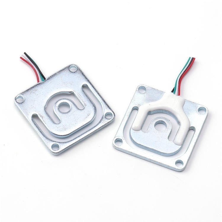
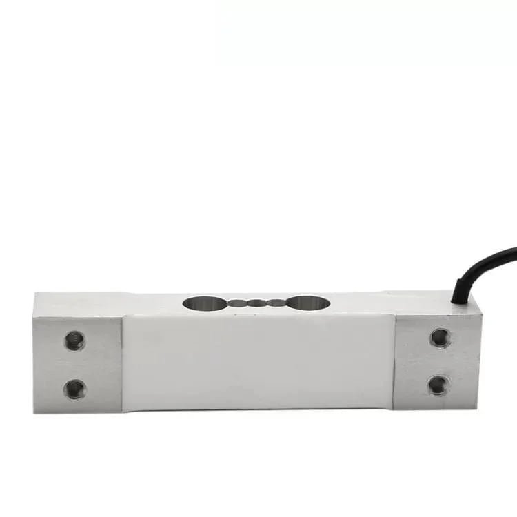
17. Load Cells I Would Actually Put On a Shrimp Feeder
Below are the parts I would quote for the two weighing jobs in Section 2 — the dose chamber and the bulk hopper — plus the accessories that make them workable. I have included the honest limitations of each, because the limitation is usually the most useful part of a specification. Full technical data is on each product page.
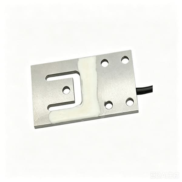

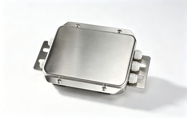
Also relevant to feeder work, and worth a look if your project needs a different capacity or mounting: the WST103 low-capacity cell (1–50 kg) for the smallest dosing cups, the WS1102 planar beam (5–25 kg) for a smaller four-corner platform, and the WST401 S-type cell (0.05–200 kN) if you weigh a bulk feed silo by hanging it rather than supporting it. For junction box wiring and how to trim corners step by step, see our guide to load cell junction box wiring and adjustment, and for the wider selection logic see how to choose the right load cell for your project.
- Load Cell Weighing Solutions for Silos and Feed Towers: An OEM Integration Guide — the bulk-feed end of the same problem, and the same load-path failures in a larger vessel.
- Precision Weighing in Agriculture: Load Cells on a TMR Feed Mixer Wagon — what happens to a weighing system when the machine moves, vibrates and mixes.
- Tank and Silo Weighing Systems: Module Selection and Installation — loss-in-weight and inventory weighing on a vessel, including capacity selection and mounting.
- How to Determine Whether the Load Cell Is Damaged — the diagnostic sequence to run before you replace anything, on a wet or corroded installation.
- Load Cells for Smart Vending Machines — another metered-dispensing problem, and how weight sensing made a machine’s own logs trustworthy.
18. Frequently Asked Questions
These are the questions feeder manufacturers and farm groups actually ask me, in roughly the order they ask them.
Why not just keep the volumetric feeder and calibrate it properly?
Because “properly” is not available for a variable material. A volumetric feeder converts volume to mass using a constant, and the constant is a property of the feed, not of the machine. The same shrimp formulation at the same pellet diameter measured 529.4 kg/m³ when extruded and 658.3 kg/m³ when ring-die pelleted — a 19.6% difference in mass per litre. Add pellet size changes, fines, humidity and head pressure, and no single constant can be right.
You can absolutely calibrate a volumetric feeder well enough for inventory and refill alarms. You cannot calibrate it well enough to defend a feed log, and a feed log is increasingly something a farm has to defend.
What dose accuracy can I realistically achieve?
On a 3 kg weighed dose chamber with a small single-point cell in a 10 kg capacity, I would expect the weighing contribution to be better than 0.1% of a 2 kg dose, and a real-world dose repeatability around 0.1–0.3% standard deviation once the metering valve’s own pulse variability is included. Anything claiming better than 0.05% on a machine with a 1,450 rpm thrower is either measuring in a laboratory or not measuring what you think it is.
Ask any supplier which number they mean: repeatability of the weighing, or accuracy of the delivered feed. They are different, and only the second one matters to a farmer.
Should I weigh the bulk hopper or a small dosing chamber?
Both, for different jobs. The bulk hopper answers “how much is left” — a 20–25 kg change, tolerance measured in percent of the hopper, and a rugged, inexpensive sensor is fine. The dose chamber answers “how much just left the valve” — a 2 kg change that you need to know to ±1%, which is 0.086% of a 25 kg hopper and therefore not obtainable from the hopper at any price.
Same tolerance target, 21.6 divisions of headroom on a 3 kg chamber versus 2.6 divisions on a 25 kg hopper. That comparison usually ends the discussion.
Can the load cell survive being washed down?
The cell usually can. The cable entry usually cannot. In wet weighing installations, the connection point — junction box and glands — is a more frequent cause of drift and failure than the cell body itself. So specify IP68 or IP69K where it is genuinely wet, but spend the design effort on glands pointing down, boxes on vertical faces, drip loops, and no horizontal surfaces near the cable run. A sealed box with an upward-facing gland is not sealed.
Do I need IP68, or is IP65 enough?
Map the machine before you decide. IP65 resists water jets but not immersion or sustained condensation, so it is appropriate inside a sealed cabinet and under a shielded chamber. IP68 is continuous immersion and belongs only at the position that is genuinely wet. IP69K is high-pressure hot-water cleaning and is worth it only if the farm actually uses a pressure washer on the machine. Buying IP68 uniformly across five positions wastes money on four of them and, in my experience, still under-specifies the one that gets hosed.
Two environment factors matter as much as IP and get ignored more often: ambient temperature against the cell’s compensated range, and bimetallic corrosion where a cell is bolted to a different metal in salt air.
How do I stop the blower and thrower vibration from corrupting the reading?
Three ways, in order of effectiveness. First and best, topology: put the thrower and blower downstream of the weighing boundary so the cell never sees the vibration. Second, sequencing: use a fast/dribble fill and take the reading in a quiet window while the blower is stopped. Third, stiffness: a thrower at 1,450 rpm is 24.2 Hz, and a mount that deflects 0.5 mm under load has a natural frequency of 22.3 Hz — resonant. Keep static deflection under 0.1 mm and you are at about 50 Hz, comfortably above the excitation.
Note what is not on the list: softer rubber isolation feet. That is the intuitive answer and it makes the problem worse by lowering the natural frequency towards the excitation.
One load cell or three or four?
It depends on the platform geometry, not on cost. A single point cell carries a platform on its own and is corner-trimmed inside the cell — ideal for a compact dose chamber. A planar beam or shear beam set is used three or four at a time; note that planar beams are generally not corner-adjusted individually, so you use three or four matched cells and trim the corners in the junction box. That buys you a platform of effectively unlimited size at the cost of a summing box and a corner-trim procedure you must actually perform.
What you should not do is use four unmatched cells at four corners and assume the average is right. It will be close when the load is centred and wrong when it is not, which on a feeder is most of the time.
How often do I need to re-verify on a pond bank?
Think in events, not in months. Re-verify after any maintenance touching the weighing structure, after relocation, after the vessel goes over-range, after junction box work, and on a calendar interval that reflects the environment — roughly twice a year indoors and quarterly on a pond bank. A calibration certificate stops being evidence the moment something in the load path changes, and on a machine that gets hosed, moved and cleaned, that happens more often than a certificate does.
The practical trick is to design a labelled, repeatable place for a test weight. When the test is easy it happens; when it is awkward it does not.
Does putting a load cell on my feeder make it ASC-compliant?
No, and any supplier who says otherwise is overselling. ASC compliance is a farm-level certification against the ASC standard, assessed by an accredited certification body, covering legal, environmental, community, operational, animal health and resource-use criteria. Feed-related requirements include record-keeping on feed conversion and use, effluent nutrient limits, and energy tracking.
What a load cell does is make the feed in number traceable to a measurement rather than a calculation. That improves the quality of the evidence a farm can present and it makes the farm’s own management decisions better founded. It is not a certificate, and it does not transfer to the farm.
Can I use these cells outdoors at 40 °C and 90% humidity?
Yes, with two caveats worth writing into the drawing. First, look at the compensated temperature range, not the operating range — our WST101 and WST1101 are both compensated from −10 to +40 °C, and a black steel cabinet in tropical sun will be well above 40 °C inside it. Shade or ventilate the cabinet. Second, all-metal sealing matters more than the IP number in salt air, and a stainless housing beats an aluminium one at any rating. Where the cell is genuinely wet, the 17-4PH stainless, O-ring-sealed, moulded-connector construction used in marine and subsea weighing is the benchmark to ask for.
No committed purchase necessary — if the answer is that your current design is fine, I will tell you that too. If it is not, I will tell you which of the three changes is cheapest: a smaller chamber, a stiffer mount, or moving the thrower behind the air line.
Load cells, force sensors, junction boxes and weighing indicators for feeder and scale builders
Written by Robin, Export Sales Engineer. I supply load cells, force sensors, junction boxes and weighing indicators to feeder, scale and equipment builders — not feeding machines or integrated farm systems. Figures quoted in this article come from published aquaculture feed and equipment literature, and from project work; verify any number against your own feed, your own machine and your own test weights before you rely on it.