

Load Cells for Beam Pumping Units: Polished Rod Load, Dynamometer Cards, and Three Field Failures I Still Think About
📅 October 5, 2026
⏱️ 14 min read
🛢️ Oilfield Case Study
A beam pumping unit — the nodding donkey, the horsehead, the pump jack — has exactly one number that tells you whether it is working: the load on the polished rod. Get that number right and your pump-off controller idles the well before it pounds fluid. Get it wrong and you shut down healthy wells, or you miss the fluid pound that parts a rod string. This is what I learned sizing polished-rod load cells for a 45-well retrofit in western Kazakhstan — and why the sensor was the last thing at fault, all three times.
I’m Robin from VektorForce. We supply load cells, force sensors, junction boxes, transmitters, and indicators to OEMs and system integrators — the weighing core, not the pumping unit.
1. Why a rod-pumped well lives or dies on one sensor
Sucker rod pumping is the most widely used artificial lift method on earth — more than 750,000 installations worldwide, with roughly 350,000 in the United States alone. In the Western Canadian Sedimentary Basin by itself there are about 200,000 pumping wells, and the great majority of them lift crude with a beam pump. That installed base is why the interesting market is not new wells; it is the digitalisation of wells that were drilled decades ago.
The numbers back that up. The Business Research Company puts the artificial lift system market at $12.18 billion in 2025 growing to $13.27 billion in 2026 (8.9% CAGR), with rod lift alone forecast to reach $5.2 billion by 2030. Grand View Research sizes the narrower pump jack market at $3.7 billion in 2025 and $3.9 billion in 2026, reaching $5.7 billion by 2033 (5.7% CAGR). The stated drivers are not new drilling — they are mature-field optimisation, digitalisation, remote monitoring and predictive maintenance. Every one of those drivers terminates, physically, at a sensor on the wellhead.
Why fluid pound is the thing you are trying to prevent:
- A rod string in normal service sees roughly 5 to 8 million stress cycles every year. It is a fatigue-limited component, and fatigue failures start at the pin or the coupling.
- When the pump runs faster than the reservoir feeds it, the barrel fills only partially. The plunger free-falls through gas on the downstroke and slaps into the fluid — fluid pound — sending a mechanical shock wave up a string that is already counting cycles.
- The fix is not a bigger pump. It is pump-off control: detect incomplete fillage on the dynamometer card and idle the unit before it pounds. Which means the entire economics of the well rests on one measurement.
That measurement is the polished rod load, and the sensor that takes it is a load cell. Everything downstream — the dynamometer card, the fillage number, the shutdown decision, the energy saving, the rod-life extension — is a derivation from that one channel. In February 2024 a pump-off controller manufacturer called me with what sounded like a load cell problem. By the time we were done it had become three problems, and not one of them was the load cell.
2. What the polished rod is actually carrying
Before you can size a sensor you have to know what the number on the vertical axis actually is. The load on the polished rod is the sum of four things, and they do not all behave the same way through the stroke.
| Component | Where it comes from | Behaviour through the stroke |
|---|---|---|
| Rod string weight | Mass of the sucker rod taper, plus buoyancy from the fluid | Always present, roughly constant — this is your baseline |
| Fluid load | Plunger area x the pressure of the fluid column above it | Appears when the travelling valve closes on the upstroke, disappears on the downstroke |
| Inertial load | Accelerating and decelerating the rod mass at each end of the stroke | Spikes near the top and bottom of the stroke; grows with strokes per minute |
| Friction | Rod against tubing, stuffing box, fluid viscosity | Opposes motion — adds on the upstroke, subtracts on the downstroke |
For the wells in the project I am about to describe — 1,850 m pump depth, a 22/19 mm rod taper, a 38 mm plunger, 5.5 to 8 SPM — the four components add up to a peak polished rod load of about 62 kN and a minimum of about 28 kN, a working range of roughly 34 kN.
Two things this budget tells you, and one it does not:
- The fluid load is only about a fifth of the peak load on a well like this. You cannot read fillage off the load magnitude alone. You read it off the shape of the card, which is why the position channel matters as much as the load channel.
- The load is not symmetric. The upstroke and the downstroke are different measurements, and the difference between them is where every diagnostic lives.
- What the steady-state budget does not include: a pump-stuck or rod hang-up event, where the peak load can climb to two or three times normal. That is a design case, not an accident, and it is the reason capacity selection is not “peak load plus 10%”.

3. From load cell to dynamometer card — and why the card needs a second sensor
Load alone is a number. Load plotted against position over one complete stroke is a dynamometer card — a closed loop with load on the vertical axis and rod position on the horizontal axis. The card is the actual product; the load cell is its front end.
There are two cards, and confusing them is a common source of argument. The surface card is the raw wellhead measurement. The downhole card (also called the pump card) is derived from it by solving the one-dimensional damped wave equation along the rod string — a computation published by Sam Gibbs in 1963 and now embedded in essentially every rod-pump controller. It strips out rod stretch, buoyancy, friction and inertia, and shows what is happening 1,500 m below the surface.
| Card shape you see | What it means | What you normally do |
|---|---|---|
| Clean parallelogram | Full pump — barrel filling completely every stroke | Leave it alone; this is the reference card |
| Top-right corner collapses | Pump-off — incomplete fillage, running faster than the well feeds | Slow the unit or shorten the run time |
| Sharp near-vertical drop late in the downstroke | Fluid pound — plunger slapping into fluid, mechanical shock | Priority fix; this is what destroys rods |
| Rounded lower-right corner | Gas interference — gas compressing under the travelling valve | Change speed; consider a gas anchor |
| Lower upstroke load | Leaking travelling valve | Plan a pump change |
| Raised downstroke load | Leaking standing valve | Plan a pump change |
| Thin, compressed card | Reduced load differential — tubing leak | Investigate tubing integrity |
| Dramatic collapse, very low load | Parted rod string | Shut in immediately |
4. Five ways to measure rod load, and where each one fails
Not every well gets a load cell, and that is often the right call. But you should know what you are giving up, because the alternatives measure something related, not the same thing.
| Method | What it actually measures | Where it fails you |
|---|---|---|
| Motor current / power | Prime-mover torque, i.e. an indirect proxy for load | Gearbox and rod friction blur the signal; cannot produce a trustworthy card; useless for a rod-stress check |
| Acoustic fluid level (gas gun or permanent acoustic) | Depth of the fluid column, hence pump intake pressure and a fillage trend | Sees fluid, not load. No valve action, no rod stress, no card. Needs a gas path; degrades with foam and heavy oil |
| Clamp-on strain gauge (polished rod transducer) | Change in polished rod diameter, converted to change in load | Measures the change, not the absolute load; the calibrations carries rod diameter and grade; the clamp itself is a failure mode |
| Beam or Samson post strain gauge | Bending strain of the structure, from which rod load is inferred | Indirect and structure-dependent; needs per-unit calibration; any structural change or repair invalidates it |
| Horseshoe or inline polished rod load cell | Direct axial load in the polished rod — the reference measurement | Must be installed between carrier bar and clamp; capacity has to cover shock loads; cable routing becomes a real design task |
5. The project: 45 beam units in western Kazakhstan
In February 2024 I got a call from an oilfield automation integrator in Dongying, Shandong. They build pump-off controllers and wellhead RTUs, and they had won a retrofit job: 45 beam pumping units in the Mangystau region of western Kazakhstan, replacing manual well checks with continuous dynamometer monitoring for their end client.
Their request to me was narrow, which I appreciated. They did not want a system. They wanted one component done properly: a load cell that fits between the carrier bar and the polished rod clamp, in the 100 kN class, with an output their RTU could already read. Two constraints shaped everything:
- Winter. Mangystau runs to about -30 °C at night. Anything that drifted with temperature would be blamed on us, fairly or not.
- Power. Several wells have no reliable grid connection and run on solar plus battery. Every milliwatt in the RTU budget matters, which is one reason a passive mV/V cell beats a smart sensor with its own electronics.
They sent me the well file: 1,850 m pump depth, 22/19 mm rod taper, 38 mm plunger, 5.5 to 8 SPM, and a calculated peak polished rod load of 62 kN. The sizing rule I used is the one I still use: capacity = 1.5 to 2 times the calculated peak, then round up into the available range. That put them at 100 kN — the bottom of the WST705 span, which runs 100 to 300 kN in one family. I also checked the other end: the minimum load of 28 kN had to stay comfortably above zero so the card would keep its area. It did.
The pilot ran through a Kazakh winter. Three things went wrong. Any one of them could have been read as “the load cell is bad”, and none of them was.
6. Problem 1: the zero reference that made good sensors look broken
Through January the field engineer in Aktau kept sending us cards. On cold mornings the baseline — the line that should represent rod weight in air — appeared 4 to 6 kN heavier than it did at midday, and the whole card floated up and down with it. Their controller classified nine wells as fluid pounding. Nine wells were being shut in every morning, and the production team was not impressed.
Their hypothesis was reasonable and it was aimed at us: the zero temperature coefficient of the load cell.
So we tested it rather than argued. I asked them to log three things every 15 minutes for three days: the raw bridge output in mV/V taken from the transmitter’s raw register before any scaling, the cell body temperature from a thermocouple taped to the housing, and whether the unit was running or idle. The result: across a 25 °C daily swing the raw bridge output moved less than 0.06% FS — about 60 N on a 100 kN cell. That is more than an order of magnitude too small to explain the 4 to 6 kN they were seeing. The sensor was innocent, and now we had the evidence.
The real cause was in their firmware. The RTU had an “auto-zero when the well is quiet” routine. The quiet detector was satisfied whenever the unit was between strokes on the VFD ramp, or during a pump-off idle — including the moment when the unit had stopped with the travelling valve not yet seated and part of the fluid column still hanging on the rod. Every one of those auto-zeros re-referenced the card to a load that was not the true rod weight. When the well restarted, every card was offset by that residual. Morning shutdowns meant morning auto-zeros, which is why it looked like a temperature problem.
What we changed, in three parts:
- Define zero as an explicit state, not a heuristic: rod at rest, unit locked out, at least 20 minutes after shutdown, confirmed by the position switch.
- Lock auto-zero behind a maintenance password so only a technician can trigger it, and log every event with a timestamp.
- Re-verify span with a proving ring after any zero event, and keep the record alongside the cell’s calibration sheet.
Card-to-card repeatability came back to ±0.8 kN.
The number I would put on a wall: on a beam pumping unit, the load cell is almost never the first thing drifting. The zero reference is. Before you send a sensor back, print raw mV/V against temperature. It costs an afternoon and it ends the argument.
7. Problem 2: the cable is a mechanical part
In May, after the freeze-thaw season, four of the 45 wells lost roughly 30% of span and turned noisy. Tapping the cable made the reading jump several kilonewtons. The integrator’s first read was blunt: two cells failing, plus two more suspect.
An insulation-resistance test on the closed loop told a different story. The loop read 40 MΩ where the data sheet asks for greater than 5,000 MΩ. That is not a strain gauge failing; that is moisture. The cells were fine.
Four hundred millimetres from each cell body, their harness had an M12 in-line connector mounted facing downward, with the cable tie-wrapped to the polished rod clamp. Condensation and dust had bridged the pins. Here is the detail that made it look like a sensor problem rather than a wiring problem: leakage across a bridge shows up first as span loss, and only later as a zero shift. So the wells read “30% weak” instead of “drifting”, and everyone pointed at the cell.
What we changed:
- Remove every connector below the carrier bar. One continuous oil-resistant, stainless-braided cable from the cell body straight to the RTU enclosure.
- Strain-relieve it properly — a drip loop plus a saddle clamp, so the cable never carries load and never flexes at the gland.
- Put the IR test on the commissioning sheet — mega-ohm the loop at handover, and re-run it at every service visit. A five-minute test that finds this class of fault before it becomes a card.
Span came back to specification on all four wells.
The rule I give customers now is short: on a moving, wet, dusty machine, do not spec a field connector below the carrier bar. The cable is a wear part — design it like one, with a continuous run, a drip loop, and its own strain relief. And remember the diagnostic order of operations: moisture ingress costs you span before it costs you zero.
8. Problem 3: a sampling rate that invented a rod part
The third problem looked the most alarming and turned out to be the most instructive. On the fastest wells — 9 to 11 SPM — their controller was producing cards with a sharp spike on the upstroke. Their pattern matcher called it mechanical shock and flagged two wells as possible rod parts. Both were shut in overnight. Separately, two cells came back from the field visibly bent after a wet shutdown where the plunger had hung up.
Three distinct failures were hiding behind one symptom.
The fixes, consolidated:
- ≥25 Hz on the load channel, with a hard floor of 20 points per stroke at your maximum SPM.
- A 4-sample moving average to knock down VFD noise without smearing the card.
- Both channels on one clock, re-synced at boot and verified in the field.
- Capacity re-matched to the worst-case well, and the mount re-drawn so the load path runs through the cell axis.
The false rod-part alarms stopped, and no further cells came back bent.
Two sentences worth carrying into your next specification: spec for the worst day, not the average day — and the sampling rate is part of the sensor spec. If your controller samples at 1 Hz, no load cell on earth will give you a usable dynamometer card.
9. How I spec a pumping unit load cell now
Everything above compresses into one checklist. This is the version I send to customers who ask “what do I actually put in the datasheet”.
| Parameter | What I specify | Why |
|---|---|---|
| Capacity | 1.5–2x calculated peak rod load, then round up | Hang-ups and shock events reach 2–3x normal peak |
| Rated range | 100 / 150 / 200 / 300 kN by well depth and plunger | A 100 kN cell on a shallow well is fine; on a deep one it is a liability |
| Comprehensive accuracy | ≤0.3% FS | Enough for fillage and pump-off decisions; more is not free |
| Creep | ≤±0.05% FS / 30 min | A card must not sag over a multi-hour run |
| Zero temp coefficient | ≤±0.05% FS / 10 °C | With a disciplined zero policy, keeps you inside ~1 kN across a winter day |
| Operating temperature | -40 to +80 °C, matched to the field | Kazakh winter to Gulf summer — check the number, do not assume it |
| Sealing | IP66/67 minimum, fully potted cable exit | Dust and condensation are the two most common killers |
| Insulation resistance | >5,000 MΩ | The first sign of moisture is span loss, not zero drift |
| Safe overload | 150% FS | Shock events are design cases, not accidents |
| Material | Alloy steel, corrosion-resistant coating | Salt spray, produced water, and in some fields H2S |
| Cable | Continuous, oil-resistant, braided; no field connector below the carrier bar | It is a wear part, and it is the most common cause of “failing sensors” |
| Output | 1.0–1.5 mV/V, low excitation option | Passive component — works with a barrier in a hazardous area |
| Documentation | Individual zero/span, shunt-cal resistor value, temperature test data | Diagnostics are only as good as the calibration record behind them |
10. Where the weighing core ends
I want to be precise about this, because it is the difference between a supplier who helps you and one who overpromises.
| What we supply | What we do not |
|---|---|
| The strain-gauge load cell and force sensor | The wellhead RTU and its firmware |
| Junction boxes, transmitters, indicators | Pump-off control and speed-optimisation algorithms |
| Bonded, sealed, oil-resistant cable assemblies | Dynamometer-card software and the wave-equation solver |
| Individual calibration record: zero, span, shunt-cal value, temperature data | Solar, battery and radio systems |
| Matched output across a batch | Hazardous-area certification of the complete wellhead assembly |
| Mounting guidance and the load-path drawing | Wellsite installation, commissioning and card calibration |
One standards note that surprises people: the pumping unit’s own structural, gearbox and load ratings are governed by API Spec 11E, and a load cell sits outside that document entirely. There is no industry standard that certifies “this sensor is right for a beam pump” — which is precisely why the individual calibration record has to stand on its own, and why we treat it as part of the product rather than paperwork that comes with it.
The load cell is a passive millivolt-per-volt component. The intrinsically-safe barrier, the enclosure rating, and any ATEX or IECEx approval of the finished wireless dynamometer belong to the integrator who assembles, certifies and supports that system. We are the weighing core: we give you the front end and the evidence behind it. That means a traceable calibration record for every cell, so that when a card looks wrong three years from now, you can separate a sensor problem from a well problem in an afternoon instead of a workover.
11. Recommended load cells for beam pumping units
Two cells cover almost everything I get asked for on a beam pumping unit — one standard wellhead sensor, one custom rod-pump sensor. Both are designed for the job rather than adapted to it.
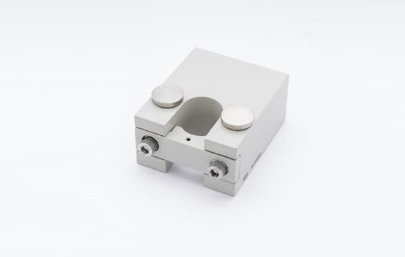
WST705 — Oilfield Load Cell
Sealed alloy-steel cell for oilfield wellhead data acquisition, with the wide capacity range that lets one platform cover a whole field.
- Rated load: 100–300 kN
- Comprehensive accuracy: 0.3% FS
- Sensitivity: 1.0–1.5 mV/V
- Creep: ±0.05% FS / 30 min
- Zero temp effect: ±0.05% FS / 10 °C
- Operating range: -20 to +65 °C
- Insulation: >5,000 MΩ; safe overload 150% FS
- Alloy steel, corrosion-, moisture- and dust-resistant
Best for: standard wellhead data acquisition on conventional beam units; installations where you want one cell family across a field of different well depths.
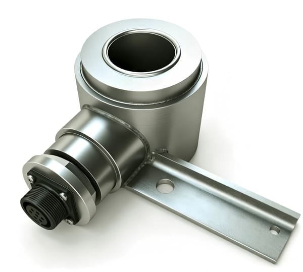
WST707 — Customized Rod Pump Load Cell
A cylindrical simply-supported beam with internal sealing, purpose-built for oil pumping unit automated testing and control signal acquisition — including wireless transmission.
- Structure: cylindrical simply-supported beam, internally sealed
- Sensitivity: 1.0–1.5 ±0.05 mV/V
- Non-linearity / hysteresis: ±0.3% FS / ±0.3% FS
- Repeatability: ±0.15% FS
- Creep: ±0.1% FS / 30 min
- Operating range: -20 to +80 °C
- Input / output: 750±20 Ω / 700±5 Ω; insulation ≥2,000 MΩ
- Excitation: 10–15 V recommended; safe overload 150% FS
- Corrosion-resistant, dust-proof, waterproof; wireless transmission enabled; direct standard signal output
Best for: rod-pump controllers and retrofit programmes where the geometry has to suit the customer’s carrier bar or bridle, and where the output needs to feed a wireless wellhead node directly.
12. FAQ
What is a polished rod load cell, and where does it mount?
It is a strain-gauge force transducer that measures the axial load carried by the polished rod. There are two common forms. The horseshoe (or donut) cell slips over the polished rod and sits between the carrier bar and the polished-rod clamp, so the entire rod load passes through it. An inline cell is built into the carrier bar or bridle assembly instead. Typical beam-pump service runs in the 0–30,000 lb (0–133 kN) class; our oilfield cells cover 100–300 kN so one range can suit a field of different wells.
Horseshoe or inline — which should I use?
Horseshoe if you are retrofitting and do not want to change the carrier bar — it is a field installation. Inline if you are building the carrier bar and want the cell out of the field-installation path. Both measure the same quantity; the real difference is who owns the mechanical integration, and how much of that integration you want to standardise across your fleet.
What capacity do I need for my pumping unit?
Start from the calculated peak polished rod load in the well file, apply a factor of 1.5 to 2, then round up into the next available range. A typical 1,800 m well with a 38 mm plunger peaks near 60 kN, so 100 kN is the floor. If your wells are deep, or prone to hang-ups and wet shutdowns, step up within the same family — we moved four wells from 100 kN to 150 kN for exactly that reason.
Does the load cell need to be explosion-proof or ATEX-rated?
The load cell itself is a passive millivolt-per-volt component, and it can be used in an intrinsically-safe circuit with a suitable barrier and a low excitation voltage. The hazardous-area approval of the complete wireless dynamometer assembly is held by the integrator who assembles, encloses and certifies that system — that is a whole-assembly question, not a component question, and it is theirs to own. We supply the front end and the calibration evidence; they supply the certification.
Will your cell work with my existing pump-off controller or RTU?
Electrically, yes, if the input matches: a 1.0–1.5 mV/V output with a 700–800 Ω bridge, excited at around 10 V. In practice the cell is rarely what breaks the chain. When a well misbehaves, check the zero policy first, then the cable and connector insulation, then the sampling rate and clock sync, and only then the sensor. That ordering is the whole point of this article.
How often should I recalibrate?
Annual verification is a reasonable default, plus a check after any pump-stuck, hang-up or rod-part event. Treat every auto-zero event in the controller as a calibration event until it is proven otherwise — that single rule would have saved the nine wells in problem 1 above.
Why do my dynamometer cards drift, go flat, or look like a rod part?
Work the chain in order: zero reference, then cable and connector insulation resistance, then sampling rate and clock synchronisation between load and position, then capacity and mounting, and only then the downhole pump. A real downhole fault and a sensor-chain fault can produce similar card shapes — which is exactly why you keep the raw mV/V log and the individual calibration record. Those two documents let you tell the difference in an afternoon.
Do you supply the complete wireless dynamometer system?
No, and we are deliberate about that. We supply the load cell, force sensor, junction box, transmitter and indicator — the weighing core, with a traceable calibration record behind each unit. The wireless transceiver, the RTU, the pump-off algorithms, the dynamometer-card software, the power system, the hazardous-area certification and the wellsite commissioning belong to the system integrator who owns the well. We would rather be excellent at one layer than mediocre at six.
Send me the well file — I’ll size the cell
Pump depth, rod taper, plunger size, strokes per minute, and your calculated peak polished rod load. That is enough for a capacity recommendation and the load-path drawing. If you already have a carrier bar design, send the drawing too.
We supply the weighing core: load cells, force sensors, junction boxes, transmitters and indicators — with a traceable calibration record. Trial orders welcome.
Get a load cell sized for your well →
Email Robin directly
VektorForce · Load cells, force sensors, junction boxes, transmitters & indicators · www.vektorforce.com