
Written by: Robin — Load Cell Export Specialist, Vektorforce
Reading time: 13 minutes | Last updated: August 2026
In This Article
- Why Tank and Silo Weighing Matters
- Case Study: A Chemical Batching System That Kept Drifting
- How a Tank Weighing System Works — The Three Building Blocks
- 4-Step Load Cell Module Selection Guide
- Weighing Module Types: Compression, Tension, and When to Use Each
- Installation Best Practices — 10 Rules That Prevent Failures
- Tank Weighing Calibration: 4 Methods Compared
- 7 Factors That Wreck Tank Weighing Accuracy (and How to Fix Them)
- Recommended Weighing Module Products
- FAQ: Tank and Silo Weighing Systems
1. Why Tank and Silo Weighing Matters in Industrial Production
I still remember the phone call. It was a Tuesday afternoon in 2019, and a project engineer from a food additives plant in Jiangsu was on the line, sounding exhausted. “We’ve got four ingredient tanks feeding into a batch mixer,” he said. “The recipe calls for 250 kg of this powder, 180 kg of that liquid — but some batches come out perfect and others are a disaster. We’re losing two batches a week, about ¥40,000 each time. I think the load cells are the problem, but I don’t know where to start.”
That conversation captures why tank and silo weighing is one of the most critical — and most frequently underestimated — measurement challenges in industrial production. Unlike a standalone floor scale that sits in a controlled environment, tank weighing systems live inside the process: they deal with thermal expansion, vibration from nearby agitators, corrosive chemicals, uneven load distribution, and operators who may not have touched a calibration certificate in years.
Key fact: In batching and formulation processes, ingredient weighing errors of just 1–2% can cause entire production batches to fail quality control. For a medium-sized chemical or food plant processing 50 tons of raw material per day, that translates to 500 kg to 1,000 kg of wasted material daily — before you even count the labor, energy, and disposal costs.
Tank and silo weighing systems solve this problem by turning the entire vessel into a scale. Instead of transferring material to a separate weigh station (slow, labor-intensive, and prone to spillage), you weigh the material where it sits — in the storage tank, the mixing hopper, or the day bin. This is called in-line weighing, and it’s the foundation of modern automated batching.
But getting it right requires more than bolting a few sensors under a tank. After helping over 60 industrial clients across Asia, Europe, and the Middle East implement tank weighing solutions, I’ve learned that the difference between a system that holds calibration for years and one that drifts within weeks comes down to a handful of decisions made during the sensor selection and installation phase.
2. Case Study: The Chemical Batching System That Kept Drifting
Let me take you through that food additives plant project, because it illustrates nearly every common tank weighing mistake in one case.
The Setup
The plant had four stainless steel ingredient tanks, each supported by three legs, feeding a central batch mixer through pneumatically actuated discharge valves. Each tank held between 2,000 and 5,000 kg of material — a mix of powders (sodium benzoate, citric acid) and liquid additives (phosphoric acid, flavor emulsions). The total system valued each batch at approximately ¥120,000, and they were producing 8–12 batches per day.
The existing setup used off-the-shelf shear beam load cells mounted on simple flat plates under each leg — no proper weighing modules, no anti-lift protection, and definitely no allowance for thermal expansion. The cables were standard PVC, zip-tied to the tank legs, running through a puddle-prone trench to a basic weight indicator in the control room.
The Problem
The symptoms were classic:
- Zero drift. Every Monday morning, the empty-tank readings had shifted by 15–30 kg. Operators were manually “zeroing” the indicator at the start of each shift, which masked the drift but didn’t fix it.
- Inconsistent batch-to-batch readings. Two tanks feeding the same recipe could show identical weight on the indicator, yet the actual discharged amount differed by up to 3% when cross-checked on the floor scale.
- Seasonal pattern. The drift was worse in winter (ambient 5–10°C) than in summer (ambient 30–35°C), which was the opposite of what you’d expect from electronic drift alone.
The Diagnosis
I spent two days on site, and here’s what I found:
- Root cause #1: Thermal expansion locking. The flat mounting plates offered zero horizontal compliance. When the stainless steel tanks expanded by 2–3 mm in summer heat, the sensor mounting bolts bound against the plates, creating a mechanical preload that the load cell interpreted as weight. In winter, the tanks contracted and the preload partially released — hence the seasonal drift pattern.
- Root cause #2: Cable moisture ingress. The PVC cables had micro-cracks at the gland entry points (PVC gets brittle below 0°C), and condensation from the trench was wicking into the strain gage cavity. Two of the twelve sensors showed intermittent zero-balance shifts consistent with moisture bridging.
- Root cause #3: Uneven load distribution. Because no one had checked the mV output at installation, one leg on Tank #3 was carrying 62% of the total weight while the other two legs split the remaining 38%. The overloaded sensor was slowly fatiguing.
- Root cause #4: No anti-lift protection. When the pneumatic discharge valve opened suddenly, the rapid material outflow created a momentary upward force on the tank. Without an anti-lift bolt, this jerked the sensor mounting and gradually loosened the bolts.
The Solution
We replaced all twelve load cells with proper weighing modules — the key being that a module is not just a sensor with a mounting plate; it’s an engineered assembly that addresses all four of the failure modes I found:
- Slotted top plates with rocker pins allow the tank to expand and contract freely in the horizontal plane without transmitting side forces to the sensor. Think of it like a self-aligning bearing for your load cell.
- Anti-lift / anti-overturn bolts prevent the tank from jumping off the sensor during sudden discharge, while serving double duty as a built-in jack for sensor replacement — no external lifting equipment needed.
- IP68-rated PUR cables with double-sealed cable glands replaced the brittle PVC wiring. PUR resists both the chemical splash (citric and phosphoric acid fumes) and the sub-zero winter temperatures.
- Individual mV measurement at installation. Before connecting to the junction box, we measured each sensor’s output under load and adjusted the mounting shims until all three legs on each tank carried within ±5% of the theoretical equal share.
The result? Six months after the retrofit, the plant reported zero batch rejections due to weighing errors — a direct saving of approximately ¥1.2 million per year. The calibration check at the 6-month mark showed less than 0.05% zero drift across all four tanks. And most importantly, the operators stopped dreading Monday mornings.
3. How a Tank Weighing System Works — The Three Building Blocks
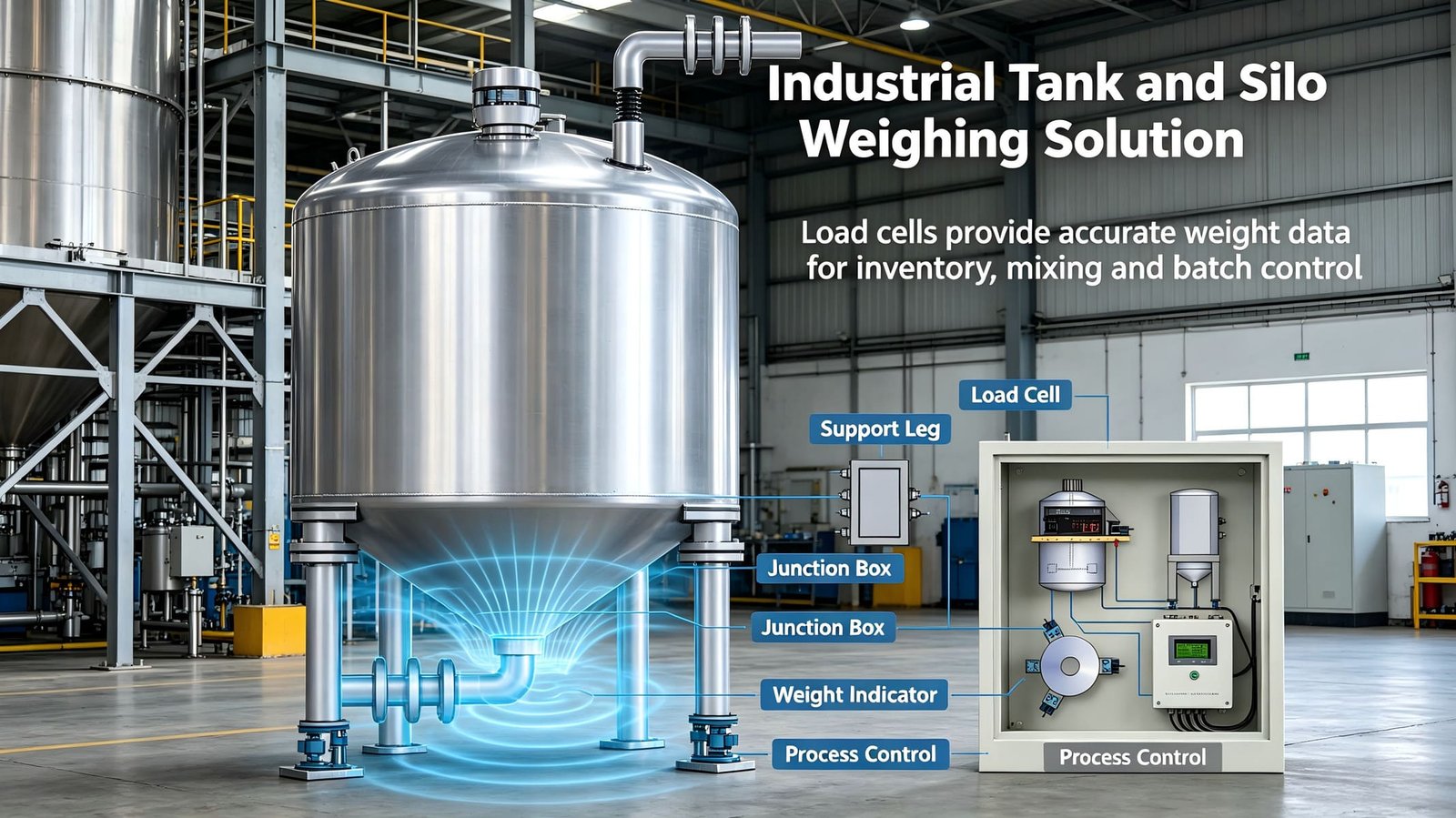
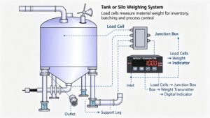
A tank weighing system is conceptually simple but deceptively detailed. Here are the three essential building blocks and what most people get wrong about each one:
Block 1: Load Cell Weighing Modules
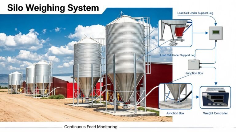
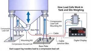
These are the sensors mounted under (or above, for hanging tanks) each support leg. The number of modules equals the number of legs — three legs = three modules. A module typically includes: the load cell itself (shear beam, bellows, spoke-type, or S-type), a top mounting plate with a self-centering rocker or spherical washer, a base plate, and an anti-lift bolt. The module is what separates a functioning tank scale from a sensor that fails within months.
Block 2: Junction Box (Summing Box)
A passive or active junction box takes the millivolt signals from 3–6 individual sensors and combines them into a single output. The minimum requirement is IP65-rated stainless steel enclosure with individual trimpots (potentiometers) for corner adjustment. This is also where you’ll land the cable shields — ground them at one point only, ideally at the junction box and not at the indicator. I’ve seen more weighing errors traced to bad junction box grounding than to bad sensors.
Block 3: Weight Indicator or Transmitter
The indicator (or transmitter, depending on your architecture) is the brain. You’ve got two main paths:
- Path A: Indicator with relay control. A full-function weight indicator (like the GSI312 series) accepts mV directly from the junction box, displays weight, and provides built-in relay outputs to control feed motors, valves, and alarms. Add RS485 or RS232 for PLC communication and analog output (4–20mA, 0–10V) for SCADA integration. This is the most common configuration for stand-alone batching systems.
- Path B: Transmitter + PLC. For plants that already have a central PLC or DCS, a weight transmitter (like the GT202 series) converts the mV signal to a standardized analog output (4–20mA or 0–10V). The PLC handles all control logic. This is cleaner for large, integrated plants but gives you less on-the-spot visibility at the tank.
4. 4-Step Load Cell Module Selection Guide
This is the decision framework I use with every new tank weighing project. Walk through these four steps in order, and you’ll arrive at a sensible sensor specification.
Step 1: Compression or Tension?
This is determined entirely by how the tank is supported. If the tank sits on legs or a skirt, you need compression-type (press-type) modules — shear beam, bellows, spoke-type, column-type, or bridge-type. If the tank hangs from an overhead structure or ceiling, you need tension-type modules — typically S-type load cells with rod-end bearings. It’s that simple. Do not use a compression sensor in tension by flipping it upside down; the mechanical interface is not designed for it.
Step 2: How Many Modules?
The number of weighing modules equals the number of tank support points. Period. Three legs = three modules, four legs = four modules. Not fewer (you’d lose stability) and not more (over-constraint causes load sharing problems).
A note on three vs. four legs: Three-point support is statically determinate — each leg always carries its fair share regardless of minor floor unevenness. If your tank has four legs but only needs to handle moderate loads, consider whether a three-point base adapter is feasible. For tall, slender tanks or ones subject to wind loads, four or more legs may be necessary for stability.
Step 3: Calculate the Required Capacity
This is where I see the most mistakes. The formula is straightforward, but the inputs require careful estimation:
Sensor Capacity ≥ K × Total Weight ÷ N
Where K = safety factor (1.25 to 2.2), N = number of sensors
Here’s how to plug in the numbers:
- Total Weight = Tare Weight + Max Material Weight. Tare weight includes the tank itself, piping, pumps, motors, agitators, insulation, heating jackets, and any permanently attached accessories. Estimate this carefully — I’ve seen plants underestimate tare by 40% because they forgot about the 300 kg agitator motor.
- Max Material Weight is the maximum net weight of contents you expect to hold. Take the tank’s rated volume, multiply by the densest material you’ll store, and add 10% for safety.
The safety factor K depends on the number of support points and the operating conditions:
| Number of Support Points | Safety Factor K | Rationale |
|---|---|---|
| 3 support points (N=3) | 1.3 | Statically determinate — load always distributes evenly |
| 4 support points (N=4) | 1.5 | Statically indeterminate — one leg could carry extra load due to uneven floor |
| 6+ support points (N ≥ 6) | 1.7 | Highly over-constrained — significant load sharing uncertainty |
| Tare > 50% of total weight | 2.0 | Large motors/accessories create non-central loads; tare estimation error risk is higher |
Real example: A 4-leg tank with 1,200 kg tare + 4,000 kg material = 5,200 kg total.
Per-sensor static load = 5,200 ÷ 4 = 1,300 kg.
Required sensor capacity ≥ 1.5 × 1,300 = 1,950 kg.
Round up to nearest standard rating: 2,000 kg (2t) sensors.
With K=2.0 (tare-heavy tank): required capacity = 2.0 × 1,300 = 2,600 kg → select 3,000 kg (3t) sensors.
Step 4: Environmental Factors
For the same rated capacity, you’ll typically find multiple sensor variants — different materials, different sealing, different certifications. Here’s the cheat sheet:
| Condition | Recommendation |
|---|---|
| Corrosive or humid | 17-4PH stainless steel body. Never use aluminum or nickel-plated steel in corrosive service. |
| Washdown / outdoor | IP68 minimum, hermetic welded seal, PUR cable. IP67 is not sufficient for daily pressure washing. |
| Explosive atmosphere | ATEX / IECEx certified intrinsically safe or flameproof sensors. Check your zone classification. |
| Seismic / high wind area | Add mechanical limit stops or tie-down brackets. Up-size sensor capacity by additional 20–30%. |
5. Weighing Module Types: Compression, Tension, and When to Use Each
Understanding the different sensor architectures available for tank weighing will save you from square-peg-in-round-hole selections. Here are the most common types:
A. Shear Beam Weighing Module (Compression)
Best for: Small to medium tanks (50 kg – 10t per leg), platform scales under hoppers, day bins.
The workhorse of industrial tank weighing. A shear beam module (GWM200-type) uses an I-beam shaped elastic element where strain is measured in the shear web. Available from 50 kg to 10t capacity per module. Comes with an integrated anti-lift bolt, rocker pin for thermal expansion, and a base plate. IP68 sealing is standard in agricultural and industrial-grade units. This is my default recommendation for any tank under about 40t total weight.
B. Bellows / Bellows-Type Weighing Module (Compression)
Best for: Small, precise tanks and hoppers (10 kg – 500 kg per leg), laboratory batching, pharmaceutical formulation.
Bellows-type modules (GWM201-type) use a thin-walled bellows structure as the spring element, giving them excellent sensitivity at low capacities. They’re not as mechanically robust as shear beams, so keep them in clean environments. Ideal for small additive tanks where a few grams matter.
C. Spoke-Type / Ring Torsion Module (Compression)
Best for: Large tanks and silos (500 kg – 100t per leg), cement silos, asphalt plants, heavy chemical storage.
The spoke-type module (GWM400-type) uses a low-profile ring with internal spokes — strain is measured in the bending of the spokes rather than in shear. This design is inherently self-centering and extremely resistant to side loads. If you’re weighing a 60-ton cement silo or a 30-ton liquid asphalt tank, this is what you use. The low profile (typically 30–60 mm height) is also an advantage where headroom is tight.
D. S-Type Weighing Module (Tension)
Best for: Hanging tanks, suspended hoppers, overhead bins, belt scale tension pickups, force measurement in test rigs.
The S-type module is used when the tank hangs from an overhead structure rather than sitting on the floor. It uses rod-end spherical bearings on both ends to ensure pure axial loading even when the suspension points aren’t perfectly aligned. Common in asphalt batching plants, cement batching towers, and any application where the tank is suspended in a multi-level structure.
| Module Type | Force Direction | Capacity Range | Best For | Relative Cost |
|---|---|---|---|---|
| Shear Beam | Compression | 50 kg – 10t | General industrial tanks / hoppers | $ |
| Bellows | Compression | 10 kg – 500 kg | Small precise tanks / pharma | $$ |
| Spoke / Ring Torsion | Compression | 500 kg – 100t | Large silos / cement / asphalt | $$$ |
| S-Type (Tension) | Tension | 50 kg – 20t | Hanging tanks / suspended hoppers | $$ |
6. Installation Best Practices — 10 Rules That Prevent Failures
I’ve walked onto sites where the sensors were correctly specified but the installation was so bad that the system never worked properly. Here are the installation rules I enforce on every project:
Mechanical Installation
- Foundation must be rigid and level. The base plates of all modules must sit on a flat, rigid foundation. Maximum height difference between any two mounting points should be less than 3 mm. Use a precision level, not a carpenter’s level.
- Tighten the anti-lift bolts. These bolts serve three purposes: prevent tank overturn, act as a built-in jack for maintenance, and protect the sensor during transport. They should be tightened to the manufacturer’s specified torque — not hand-tight, not impact-gun tight.
- Top and bottom plates must be parallel and aligned. The force vector must enter the sensor vertically. Even a 2° tilt can introduce 3–4% error. Use shims under the base plates to correct any angular misalignment.
- Use shims for load equalization. After installation, power up the system and measure the mV output of each sensor individually. The output should be within ±5% of the average across all sensors. If one sensor is significantly higher or lower, add shims under that module to redistribute load.
- Never weld near an installed load cell. Welding current will travel through the sensor body and permanently damage the strain gages. If welding is unavoidable near the modules, disconnect the sensors completely, ground the welding clamp directly to the workpiece (maximum 30 cm from the weld point), and route the ground path away from the sensor mounting area.
Electrical Installation
- Use shielded, insulated cables only. All signal wiring must be shielded twisted pair. The shield should be grounded at one point only — typically at the junction box — to avoid ground loops.
- Separate power and signal cables. Run sensor cables in a separate conduit or cable tray from motor power cables, VFD drives, and welding cables. Maintain at least 30 cm separation. If you must cross a power cable, do it at 90°.
- Never cut or extend sensor cables. The cable length is part of the calibration — cutting it changes the bridge impedance and shifts the calibration. If you need a longer run, use the junction box as the extension point and keep the sensor cables at their factory length.
- Protect the junction box. The junction box should be mounted in a dry, accessible location. If it must be outdoors, use an IP68-rated enclosure and seal the cable entries with PG glands and silicone. I’ve seen junction boxes that were perfect installations but opened six months later to find them half full of water.
- Add mechanical cable protection. Use flexible conduit or spiral wrap on any exposed cable runs. On outdoor tanks, route cables along the inside of the support structure where they’re shielded from weather, UV, and accidental impact from forklifts or maintenance equipment.
Quick Tip: The 30-Second mV Check
Before wiring sensors into the junction box, connect each sensor individually to the indicator and read its mV/V output under the same dead load. Write down the readings. If one sensor’s output differs by more than 10% from the others, stop and investigate — it’s either overloaded, misaligned, or faulty. Don’t sum them together until they’re individually verified.
7. Tank Weighing Calibration: 4 Methods Compared
Calibrating a tank scale is fundamentally different from calibrating a bench scale. You can’t just stack test weights on top of a 50-ton silo. Here are the four methods, ranked from most accurate to least:
Method 1: Full Deadweight Calibration
Accuracy: Highest | Practical for: Small tanks only (under ~2t total)
You load the tank with calibrated test weights equal to the full-scale capacity. This is the gold standard but rarely practical for industrial tanks. For small additive hoppers (100–500 kg), it’s still the preferred method.
Method 2: Gradual Substitution (Most Common for Medium Tanks)
Accuracy: High | Practical for: Tanks 2t – 30t total
This is the method I recommend for 80% of tank weighing projects. Here’s the procedure:
- Calibrate with 10–20% of full-scale using certified test weights.
- Add water (or another measurable fluid) until the weight matches the calibrated load.
- Add another increment of test weights and calibrate again.
- Repeat, alternating weights and fluid, until you reach full scale.
The advantage is that you only need 10–20% of the full-scale weight in physical test weights. The fluid fills the gap, and the incremental calibration corrects for any fluid-weight errors. I’ve used this method successfully on tanks up to 30,000 kg.
Method 3: Material Transfer
Accuracy: Moderate | Practical for: Large tanks where fluid substitution isn’t feasible
Weigh a batch of material on a separate calibrated scale, then transfer it into the tank and use that weight as the calibration reference. The accuracy is limited by the reference scale’s accuracy and any material loss during transfer. Repeat at multiple load points for best results.
Method 4: Electronic Simulation (mV Calibration)
Accuracy: Lowest | Practical for: Quick checks, emergency replacement, or when physical calibration is impossible
A load cell simulator generates a known mV/V signal to simulate a specific weight. You enter the sensor’s rated output (e.g., 2.0 mV/V at 5,000 kg) into the simulator, and the indicator scales accordingly. This method assumes the mechanical installation is perfect and the sensors match their data sheets exactly — which is rarely true. Use this only when you can’t do better, and plan a proper calibration as soon as possible.
| Method | Accuracy | Equipment Required | Max Practical Tank Size |
|---|---|---|---|
| Full Deadweight | ±0.02–0.05% | Full-scale test weights | ~2,000 kg |
| Gradual Substitution | ±0.05–0.1% | 10–20% test weights + fluid source | ~30,000 kg |
| Material Transfer | ±0.2–0.5% | Calibrated reference scale | Unlimited (practical limits apply) |
| Electronic Simulation | ±0.5–1% | mV simulator | Unlimited (accuracy degrades) |
8. 7 Factors That Wreck Tank Weighing Accuracy (and How to Fix Them)
Even with correctly specified sensors and a careful installation, tank weighing systems face ongoing environmental challenges. Here are the seven most common accuracy killers and the countermeasures I use:
8.1 Wind Loading
Tall, slender tanks act like sails. Wind creates downward pressure on the windward side and uplift on the leeward side, plus lateral shear. For outdoor silos over 10 meters tall, wind can add or subtract several hundred kilograms of apparent weight. Solutions: up-size sensor capacity, add mechanical tie-downs or wind shields, and if possible, locate tall tanks in sheltered areas.
8.2 Impact Loading
Dropping material from height into an empty tank generates impact forces that can momentarily exceed 2–3x the static weight. Over time, this damages sensors. Solutions: use sensors with higher safe overload rating, install impact buffers or wear plates inside the tank at the fill point, and reduce the free-fall height of incoming material.
8.3 Vibration
Agitators, nearby conveyor belts, pumps, and even passing trucks create vibration that couples into the weighing structure. The indicator sees a noisy weight signal and either averages it (losing response time) or follows it (giving unstable readings). Solutions: isolate the agitator mount from the tank weighing structure, install vibration-damping pads under sensor base plates, and use a weight indicator with adjustable digital filtering.
8.4 Thermal Expansion
A stainless steel tank that’s 4 meters tall will expand by approximately 2.4 mm between a winter morning at -10°C and a summer afternoon at 50°C. If the sensor mounting doesn’t allow this movement, the resulting side force can create errors of 5–10%. Solutions: use weighing modules with rocker pins or spherical washers that allow horizontal displacement, and add insulation between the tank and the sensor to slow the rate of temperature change.
8.5 Lightning and Electrical Surge
A nearby lightning strike can induce kilovolts on sensor cables, instantly destroying strain gages. Even non-lightning surges from large motor startups can degrade sensor performance over time. Solutions: single-point grounding of the entire weighing system, surge protection devices at the junction box and indicator, and ensuring the tank structure itself has a proper earth ground.
8.6 Pressure Imbalance (Breathing)
When material flows rapidly into or out of a sealed tank, the air inside can’t equalize fast enough. This creates a pressure differential — positive pressure during filling pushes down on the tank top, negative during discharge pulls up. Either effect shows up as a weighing error. Solutions: install adequate vent ports or breather filters on the tank, sized for the maximum fill/discharge rate.
8.7 Structural Deflection
If the tank’s support legs are long and slender, they’ll bow outward slightly under full load. This creates a non-vertical force component at the sensor, reducing linearity. A 10-meter-tall leg with only 100 mm cross-section can deflect several millimeters. Solutions: reinforce the support structure with cross-bracing or gussets, and use wider, stiffer leg sections.
9. Recommended Weighing Module Products for Tank Applications
Based on my experience sourcing and supplying these systems to clients worldwide, here are the key product categories and their typical specifications:
| Product | Model | Capacity Range | Key Features |
|---|---|---|---|
| Shear Beam Weighing Module | WST803 | 50 kg – 10t | Anti-lift bolt, rocker pin self-centering, IP67/IP68, alloy or stainless steel options |
| Bellows Weighing Module | WST804 | 10 kg – 500 kg | High sensitivity, anti-lift & anti-overturn protection, compact design |
| Spoke / Ring Torsion Module | WST801 | 500 kg – 100t | Low profile, self-centering, excellent side-load resistance, anti-lift bolt included |
| Junction Box | WST1513 | 4-in-1-out / 6-in-1-out | Stainless steel enclosure, individual trimpots, mV output |
| Weight Transmitter | Optional | N/A | 1-ch / multi-ch, outputs 4–20mA, 0–5V, 0–10V, ±5V, ±10V |
| Weight Indicator | Optional | N/A | 4-digit or 6-digit display, 2–3+ relay outputs, optional analog output or RS485/RS232 |
10. Frequently Asked Questions About Tank and Silo Weighing
Q: Can I use 3 load cell modules on a tank with 4 legs?
Technically yes, but you’d need to fabricate a sub-frame or adapter plate that transfers the load from four legs to three weighing points. Three-point weighing is statically determinate and often more accurate, but the mechanical modification adds cost and complexity. If the tank already has four legs and the loads aren’t extreme, stick with four modules — just take extra care with shimming during installation.
Q: What accuracy can I realistically expect from a tank weighing system?
With proper sensor selection, correct module installation, and a full deadweight or substitution calibration: ±0.1% to 0.2% of full scale is achievable. With electronic calibration only and average installation quality, expect ±0.5% to 1%. The difference between 0.1% and 1% on a 20-ton tank is 200 kg — that’s a lot of wasted or miscounted material.
Q: Do I need explosion-proof load cells for my tank?
It depends on your zone classification. If the tank stores flammable liquids (solvents, fuels), combustible dusts (flour, grain dust, coal), or is in a classified hazardous area, you need ATEX or IECEx certified sensors, junction boxes, and cable glands — the entire signal chain, not just the sensor. Check your local hazardous area classification (Zone 0/1/2 for gas, Zone 20/21/22 for dust) and select certification accordingly.
Q: How do I handle pipe connections to a weighed tank?
Rigid pipe connections create a mechanical parallel load path — some of the tank weight bypasses the load cells and travels through the pipes. This is one of the most common causes of chronic weighing error. Solutions: use flexible bellows or rubber expansion joints in all pipe connections, route pipes horizontally (not vertically) for at least 1–2 meters before any vertical run, and ensure pipe supports are independent of the tank weighing structure.
Q: How often should I recalibrate a tank weighing system?
At minimum, annually for systems in stable, indoor environments with clean materials. For outdoor systems, systems handling corrosive or abrasive materials, or systems subject to temperature extremes, every 6 months. For legal-for-trade or pharmaceutical applications, follow your regulatory schedule (often quarterly or semi-annual). Between formal calibrations, do a simple zero check weekly — if the empty-tank reading drifts by more than 0.1% of full scale, investigate before it gets worse.
Q: What is the difference between a load cell and a weighing module?
A load cell is just the sensor element — the spring body with strain gages and a cable. A weighing module is the complete assembly: load cell + top plate with self-centering mechanism (rocker pin or spherical washer) + base plate + anti-lift bolt + mounting hardware. The module handles thermal expansion, prevents overturning, and simplifies installation. For tank weighing, always use modules, not bare sensors. The cost difference is negligible compared to the cost of a failed installation.
Final Thoughts: A Good Tank Scale Is Built, Not Bought
If there’s one message I want you to take from this article, it’s this: the load cell is just one piece of the puzzle. I’ve seen plants buy premium ¥8,000 sensors and bolt them to a wobbly, un-level foundation with no junction box protection. The result? A ¥40,000 weighing system that performs worse than a properly installed ¥8,000 system.
The sensors, the modules, the junction box, the cabling, the indicator, the foundation, the calibration method — they all have to work together as a system. When they do, tank weighing is the most reliable, lowest-maintenance measurement system in your plant. When they don’t, it’s a constant source of frustration.
At Winsentek, we don’t just supply load cells. Our engineering team — with decades of combined experience from sensor industry leaders like Zemic, Flintec, and Anyload — helps you select the right weighing modules, junction boxes, indicators, and transmitters for your specific application. We can customize sensor dimensions, capacities, cable lengths, and even connector types to match your existing tank footprint, eliminating the need for structural modifications.
Whether you’re setting up a single ingredient hopper or an entire multi-tank batching line, I’d be happy to look at your project and help you get it right the first time.
Need a Custom Tank Weighing Solution?
We provide OEM-customized weighing modules for tanks, silos, hoppers, and batching systems.
Shear beam, bellows, spoke-type, S-type — alloy steel or stainless — IP68 sealed — custom dimensions available.
About the Author
Robin is a load cell export specialist at Vektorforce with over 10 years of experience in designing and supplying precision weighing sensors for tank and silo weighing, industrial batching, and process control applications. He has personally managed weighing module customization projects for OEMs across 20+ countries, helping chemical plants, food factories, and construction material producers achieve reliable in-line weighing.