
Case Study · Scissor & Boom Lifts · Load Monitoring
Load Cells for Lifting Platforms: Field Notes from 200+ Projects
How we help scissor-lift OEMs, LMI integrators and rental fleets add overload protection and payload monitoring — without building the machine. Three real projects, four sensing topologies, and the selection habits that save our customers months.
⏱️ 14 min read
👤 By Michael — Export Sales Engineer
1. Why I’m Writing This
A few months ago I got an email from a scissor-lift manufacturer on Turkey’s Aegean coast. They had just started serial production of a 12 m electric machine, and their CE technical file called for overload protection on the platform. They had tried to source “an overload sensor” and ended up with three quotes that made no engineering sense to them — a hydraulic pressure switch, an expensive in-cab load-cell kit from a competitor, and a proposal to redesign the platform. So they wrote to us instead, and asked the question I now hear almost weekly: “We don’t know if we need a load cell, a pressure sensor, or something else. Can you help us figure out what to buy?”
I’ve spent a decade exporting load cells, force sensors, junction boxes and weighing indicators — not building lifting platforms. And that distinction matters more than people think. The companies that buy from us are exactly the ones in that email: machine OEMs who need a sensing backbone, electronics houses who build load-monitoring systems, and rental fleets who must prove their machines are safe. None of them want us to design their lift. They want a partner who understands force measurement deeply enough to recommend the right cell, wire it into their existing controller, and not disappear when a prototype misbehaves.
This article is the field-note version of that advice. It walks through three projects from our order book — a scissor-lift OEM, a load-monitoring integrator, and a rental fleet — the exact products we shipped, the mistakes we caught, and the selection path we now use on every inquiry. If you build, integrate or operate lifting platforms, I hope it saves you the expensive part of the learning curve.
💡 Key Takeaway
For overload protection and payload monitoring on lifting platforms, the question is rarely “load cell or pressure sensor?” — it’s which force-sensing topology matches your machine’s geometry. A load pin on a boom pivot, a rope-tension cell on a cable drive, or four compression cells under a scissor platform are three different answers to three different problems. We supply the sensing core for all three; your engineering team keeps control of the machine.
📈 Why This Market Is Growing
The global aerial-work-platform market was worth roughly USD 12 billion in 2025 and is forecast to grow at about 5–6% per year through the next decade, with scissor lifts and boom lifts together representing close to 80% of demand (industry market reports, 2026). Two forces push force sensing deeper into these machines: tighter safety standards — ISO 16368:2024 (the updated international MEWP standard), EN 280 in Europe, ANSI/SAIA A92 and CSA B354 in North America — and rental fleets adding payload data to their telematics. Every one of those machines needs at least one force sensor, and most need two or three.
📋 What This Article Covers
- Where Force Sensing Fits Inside a Lifting Platform
- What We Supply (and What We Don’t) — the Weighing-Core Approach
- Project 1 — Scissor-Lift OEM in Turkey: Overload Protection That Stopped Crying Wolf
- Project 2 — German Load-Monitoring Integrator: Custom Load Pins Under Their Brand
- Project 3 — Rental Fleet in the Gulf: Proof Tests & Retrofits Across 180 Machines
- The Specs We Actually Shipped — Side by Side
- A 7-Step Selection Path We Use on Every Inquiry
- Mistakes We See Repeated (and You Can Avoid)
- A Note on Standards: Who Owns Compliance
- Frequently Asked Questions
- Recommended Force-Sensing Building Blocks
- Let’s Spec Your Sensing Core Together
2. Where Force Sensing Fits Inside a Lifting Platform
Before any talk of millivolt outputs and accuracy classes, we sit down with the customer’s drawings and answer one question: what force actually tells you the machine is overloaded? Depending on the platform type, the answer changes completely:
| Machine Type | What Needs Measuring | Typical Sensor Location | Preferred Topology |
|---|---|---|---|
| Scissor lift (electric) | Platform payload | Under platform corners | 4 × compression cells → junction box |
| Boom / articulated lift | Basket load & tipping moment | Pivot pins, basket mounting | Load pin (shaft-pin cell) or basket cells |
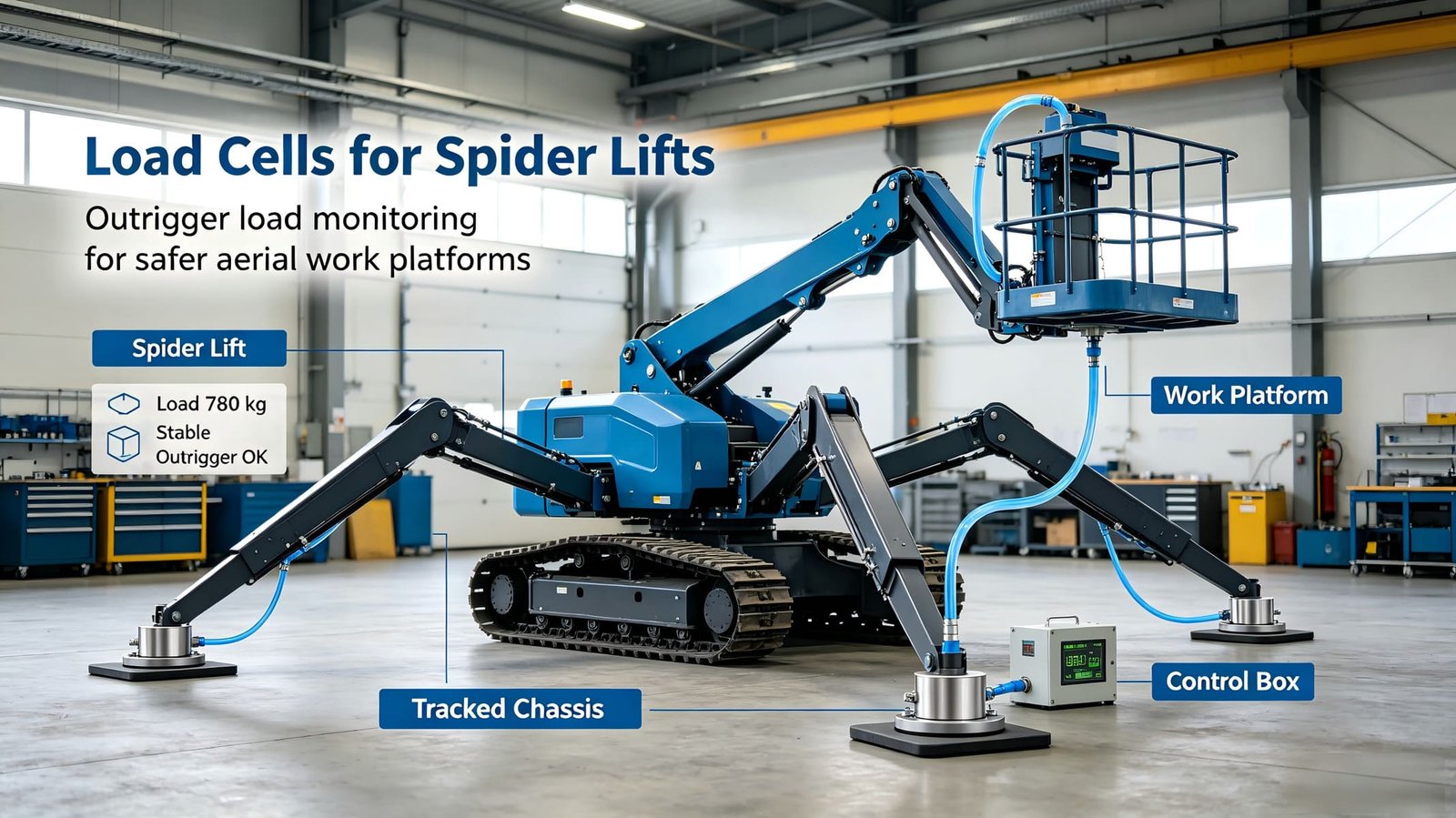
| Spider / crawler lift | Stabilizer ground load | Outrigger feet / pads | Compression force cells per stabilizer |
| Vertical mast / cable lift | Haul-rope or chain tension | Inline on rope or chain run | Rope-tension cell / tension link |
| Truck-mounted platform / crane | Rated-capacity & moment limit | Boom pivot, outriggers, winch rope | Load pins + tension cells (LMI) |
| Freight / goods lift | Carriage load | Under floor / on actuators | Column or shear-beam cells |
One honest warning before we go further: a rope-tension cell measures rope tension, not payload. Reeving geometry, pulley friction and machine inertia all introduce error, so tension-based systems are usually tuned for alarm thresholds with a comfortable margin rather than for displaying an exact kilogram figure. When a customer genuinely needs a legally defensible platform weight, direct load measurement under the platform is the better road. That distinction — alarm vs. measurement — shapes every recommendation we make.
3. What We Supply (and What We Don’t) — the Weighing-Core Approach
Let me be direct about our role, because it saves everyone time. We do not build lifting platforms. We don’t design your hydraulic circuit, we don’t write your safety-logic firmware, and we don’t issue EN 280 or ANSI compliance certificates for your finished machine — those belong to you and your notified body.
What we do is build and engineer the weighing core that sits inside your machine — and we’ve been doing it since 2004:
✅ What we supply
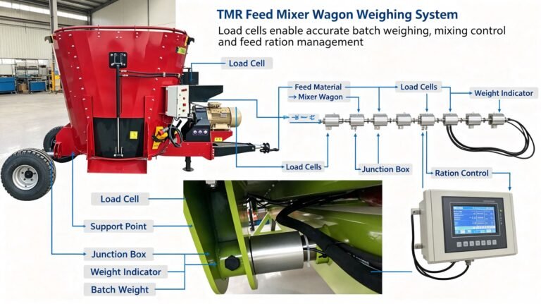
Force sensors in the shape your machine needs: load pins that replace existing pivot shafts, rope-tension cells for cable drives, column and spoke compression cells for platform and outrigger mounting, and custom mechanical adapters. Capacities from a few kg to 200 t.
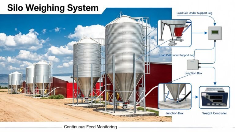
Signal summing and conditioning: stainless multi-channel junction boxes that combine four or eight cells into one clean output.
Intelligence and outputs: weighing indicators and transmitters with relay setpoints (for your warning/cut-off logic), 4–20 mA, 0–10 V, RS485 Modbus RTU or Profibus-DP, so our load signal drops straight into your PLC or controller.
Engineering support: application advice, wiring schemes, calibration data and test evidence for every cell — so your integration team can focus on the machine, not on fighting a sensor.
White-label / OEM service: we’ve shipped cells under our customers’ own part numbers and brand — common in this industry, and we’re happy to set it up.
A typical scissor-lift signal chain we ship looks like this — four corner cells, a junction box, and an indicator whose relay contacts feed your machine’s existing safety logic:
Signal chain (typical):
4 × compression cells (mV/V) → stainless junction box (summing + corner trim) → weighing indicator/transmitter → relay output (alarm @ 100% SWL, lock-out @ 110%) → your machine safety circuit
Need 4–20 mA or Modbus instead of relays? The same chain ends in a transmitter and your PLC does the logic. We support both, and we’ll draw the wiring diagram with you.
4. Project 1 — Scissor-Lift OEM in Turkey: Overload Protection That Stopped Crying Wolf
Back to that Aegean-coast manufacturer. Their 12 m electric scissor lift has a rated platform load of 450 kg, and their overload-protection spec is typical of the industry: an audible/visual warning when the platform approaches rated load, and a function lock-out before it can exceed it. They asked us for “a load sensor that can handle 500 kg.”
Our first instinct — and theirs — was a single compression cell under the center of the platform. It would have been cheaper. It would also have been wrong. A scissor platform is supported on two longitudinal rails with the scissors structure below; the load path is never through one point, and two workers standing at one corner easily put 70% of the total on two of the four support feet. A single center cell either reads an average that hides a real overload, or gets destroyed by the bending moment it was never designed to carry.
We went back with a different proposal: four compact compression cells, one at each platform support corner, wired into a stainless junction box, feeding a process indicator with two relay setpoints. Each cell was rated 1,000 kg — not 500 — for three reasons: corner-heavy loading can push 60–70% of platform load onto one cell; the platform is a dynamic system (raising, lowering, driving over rough ground); and cells live happier at 30–50% of rated capacity, where their linearity is best.
💡 The lesson that cost us a prototype: never rate the cell on total platform load divided by four. Rate each cell so that it survives the worst-case corner share with headroom. In their case that meant 1 t cells for a 450 kg platform.
Then the real problems started — and this is where a sensor supplier earns their keep. On the test machine, the alarm fired while the platform was empty, every time the machine drove over a threshold or a worker stepped aboard. The cause wasn’t the cells; it was that a scissor mechanism momentarily sees reaction forces far above the static payload when the machine accelerates or tilts. We fixed it three ways, together with their controls engineer:
- Filtering and setpoint hysteresis in the indicator — the alarm relay only latches when the reading holds above threshold for a configurable time, and the lock-out threshold sits above the alarm band so the system can’t oscillate.
- A plausibility window — the indicator ignores readings while the drive is in motion (a simple digital input from their controller), so travel-induced transients never reach the alarm logic.
- Mechanical pre-load — each corner cell is mounted with a controlled pre-load so the platform stays seated on its stops under negative acceleration; the cell then measures load changes cleanly instead of rattling.
After tuning, the machine passed its factory overload test with a clear margin: warning at 450 kg, function lock-out at roughly 495 kg, and — the detail the customer still mentions in emails — zero false alarms in the first year of production. They now order the corner-cell kit as a standard option on every platform they build. The whole sensing chain — four cells, one junction box, one indicator — cost them a fraction of the in-cab “overload system” quote they had received, and they kept full control of the logic.
5. Project 2 — German Load-Monitoring Integrator: Custom Load Pins Under Their Brand
The second customer is the opposite of the first: a southern-German electronics house that builds load-monitoring (LMI) and rated-capacity systems for boom lifts, mini crawlers and truck-mounted platforms. They don’t need us to explain what a load cell is — they need a supplier who can execute their designs to the letter, in their brand, without leaking their product plans to their competitors.
Their problem was simple on paper, brutal in practice. For a boom lift, the classic way to sense load and moment is to replace an existing pivot pin with an instrumented one: a load pin that carries the same mechanical load and outputs a millivolt signal proportional to the shear force on it. They supported six machine models with fourteen different pin sizes, from 25 mm to 90 mm diameter, in both clevis and shoulder configurations. Every size needed the same electrical performance, the same IP rating, and the same delivery rhythm — and they wanted their own part numbers on the body.
The engineering traps were exactly what you’d expect in a dirty, wet, vibrating environment:
- Sealing. Pins live inside pivot joints that get pressure-washed daily. We build these in stainless steel with a welded cable exit and an IP68-rated connector, and we run a 48-hour immersion sample on every batch.
- Mechanical identity. A load pin must be a drop-in replacement — same diameter tolerance, same shoulder geometry — or the customer’s whole clevis design changes. We machine from their 2D drawings and supply dimensional reports with every order.
- EMC. Their electronics sit next to inverter drives and radios. We tune the cell’s shielding and cabling to the EMC levels their CE file requires, and we share the test data rather than making them discover interference on the test bench.
- Calibration traceability. Every pin is loaded on our test rig against a master load cell and shipped with an individual calibration report — they audit our records, not just our datasheets.
Two years in, the field data is the part that makes this relationship stick. Their service team tracks every returned pin; over 24 months in coastal and desert sites, drift on zero stayed inside ±0.3% of rated output, and the only failures were two units with mechanically damaged connectors — which we redesigned with a recessed outlet on the next revision. Today those pins carry the customer’s logo, ship under their part numbers, and we’re effectively their remote load-cell R&D department.
6. Project 3 — Rental Fleet in the Gulf: Proof Tests & Retrofits Across 180 Machines
The third project shows a completely different side of load sensing: the aftermarket and verification business. A rental company in the United Arab Emirates runs a fleet of scissor lifts, boom lifts and vertical-mast machines on construction sites where site-safety rules and insurers require documented load testing. Their old process was painful: rent a calibrated dynamometer, queue for it, test machines one by one, argue with site safety officers about the numbers.
We equipped them with our wireless dynamometer load links and handheld displays — instrumented shackles that hang on the lifting point or rope, measure the force, and stream it to a handheld receiver. The rig for a boom-lift proof test is simple: hang a known test weight, lift slowly, and record the reading at the moment the wheels just clear the ground. What used to take a rented crane and a week of scheduling now happens in an afternoon, with a printable test record for the safety file.
⚠️ The desert is a brutal teacher
In 50°C ambient with sand in the air, battery life and ingress rating decide everything. We specced the load links with IP65+ housings and a charging dock per machine bay, and we trained their crew to check the link’s zero before every test — sand in the shackle threads alone caused two “failures” that were actually just a dirty pin. Lesson: in harsh environments, operator habits matter as much as the sensor.
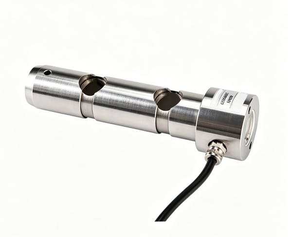
Alongside proof testing, they asked us to retrofit twelve cable-driven vertical mast lifts with overload sensing. Those machines have no platform cells and the budget didn’t allow a platform redesign, so we installed rope-tension cells (WST702) inline on the haul rope, feeding a small transmitter whose 4–20 mA signal goes to their existing telematics unit. As I noted earlier, rope tension is not the same as payload — so we set the alarm conservatively and documented the relationship between rope tension and platform load during commissioning. The retrofit took a weekend per machine, cost a fraction of a new-machine solution, and gave the fleet owner what the site auditor actually wanted: a documented overload protection function on every machine.
7. The Specs We Actually Shipped — Side by Side
| Parameter | Project 1 — Scissor OEM | Project 2 — Load Pins | Project 3 — Rope Tension |
|---|---|---|---|
| Sensor type | Compression cells × 4 | Shaft-pin load cells | Rope-tension cells |
| Capacity | 1,000 kg per cell | Custom, 25–90 mm bore | 10–200 kN (≈1–20 t) |
| Combined error | ≤ ±0.05% FS | ≤ ±0.5% FS (typical) | ≤ ±0.3% FS |
| Material / sealing | Alloy steel, painted; IP67 option | Stainless steel, welded cable, IP68 | Alloy steel, nickel-plated; IP65+ |
| Output | mV/V → junction box → indicator relays | mV/V → customer’s LMI amplifier | mV/V → transmitter 4–20 mA → telematics |
| Operating temp. | −20…+60 °C | −20…+60 °C | −20…+60 °C |
8. A 7-Step Selection Path We Use on Every Inquiry
When a customer sends us a drawing or a load profile, we walk this exact sequence. It takes us about a day to come back with a recommendation; here it is so you can sanity-check any quote you receive — including ours:
- Find the load path. What force is the honest indicator of overload for this machine geometry — platform weight, pivot shear, rope tension, stabilizer reaction? (Section 2 above.)
- Fix the worst-case corner. Never size by “total load ÷ number of cells.” Compute the worst asymmetric share plus dynamic factor — for people-carrying platforms we commonly use 1.5–2× static margin, and cell rated capacity should still sit at 30–50% of its range at normal load.
- Decide alarm vs. measurement. Overload protection is an alarm function — ±1–3% of threshold is usually plenty. If you also display payload or feed legal records, accuracy and traceability requirements tighten. Don’t pay for C3 trade accuracy you don’t need; don’t skimp on repeatability if you do.
- Match the environment. Outdoor machine → stainless or nickel-plated alloy, IP67 minimum, sealed cable exit, connector orientation that sheds water. Indoor electric scissors can often use painted alloy cells — cheaper and perfectly adequate.
- Pick the output that your system actually speaks. Raw mV/V to your own amplifier, or relay setpoints / 4–20 mA / Modbus RTU from our indicator or transmitter. Match it to your controller’s inputs — a great cell with the wrong output is a doorstop.
- Design the mechanical interface. For load pins: bore diameter, shoulder geometry, tolerance, bolt pattern — we machine exactly to your drawing so it’s a 1:1 drop-in replacement. For platform cells: footprint, mounting plate, pre-load method.
- Verify, don’t assume. Ask for the individual calibration report, the IP test method, and the fatigue/reliability data. If a supplier can’t produce test evidence, that’s your answer about whether to buy from them.
9. Mistakes We See Repeated (and You Can Avoid)
- Sizing on nominal load, not worst-case corner. The single most common mistake in scissor-lift projects. See Project 1 — it cost us a prototype cycle to learn.
- Ignoring dynamics. Platforms accelerate, bounce and tilt. A sensor that’s correct in the lab but trips on every pothole gets disabled by operators — which is worse than no sensor at all.
- One point of failure in a safety function. If one cell fails and the alarm goes silent, the machine is unprotected. Your machine-level safety architecture should detect cell faults (we support open-circuit and shorts detection on our indicators), and final safety-critical decisions belong to your safety circuit, not just our relay.
- Junction boxes in the splash zone. A summing box bolted where it gets hosed down will fail — buy the stainless sealed version and mount it high.
- Treating rope tension as payload. Reeving friction and geometry make tension a proxy, not a measurement. Fine for conservative alarms, dangerous if you publish it as platform weight.
- Forgetting the temperature on zero. A cell’s zero drifts with temperature. For a threshold that must hold across a 50°C desert day, spec the temperature coefficient on zero explicitly.
- No periodic verification. Load cells are mechanical parts — they can be damaged by a dropped load or a bent cable. Annual proof testing (Project 3 style) should be in your fleet SOP, not an insurance surprise.
10. A Note on Standards: Who Owns Compliance
Force sensors in lifting platforms support functions that are governed by machine-level standards: EN 280 for mobile elevating work platforms in Europe, ISO 16368:2024 as the international design and testing reference, ANSI/SAIA A92 and CSA B354 in North America, and the AS 1418 family in Australia — plus, for crane-integrated platforms, load-moment-indicator requirements. Different markets, different audit paths, same principle: the finished machine is certified by its manufacturer, using components that must come with their own documentation and test evidence.
⚠️ What we do and don’t claim
As a component supplier, we do not hold — and do not claim — EN 280, ANSI A92 or similar whole-machine certifications. What we provide is component-level: calibrated load cells with individual test reports, IP and temperature performance data, EMC test evidence, and the application engineering to help your team integrate them. The machine-level compliance statement belongs to you and your notified body — and we’re glad it does, because that’s not our business. It’s yours.
One practical tip from the field: when you open your CE or ANSI file, your assessor will ask where the overload-sensing components came from and how they’re verified. Suppliers who can hand you calibration records, material certificates and a quality agreement will save your certification schedule months. That’s a real selection criterion, not paperwork for paperwork’s sake.
11. Frequently Asked Questions
Can a load cell detect overload on a scissor lift, or do I need a pressure sensor?
Both can work, but they measure different things. A hydraulic pressure sensor reads the pump/cylinder circuit — it reflects what the machine is doing, not necessarily what is on the platform, and it needs careful compensation for cylinder friction and geometry. Load cells under the platform measure the payload directly. For people-carrying machines where the platform load is the safety quantity, we usually recommend direct load measurement; pressure sensing is a legitimate option when there is no practical load path to the platform.
Can you retrofit overload sensing to an existing lift without redesigning the platform?
Often, yes. The lowest-intrusion options are load pins that replace existing pivot shafts (no platform changes), or rope-tension cells inline on cable/chain drives. Both need a commissioning step to set realistic thresholds, and neither should be presented as a precision payload measurement — but for documented overload protection on an existing fleet, they’re the fastest, most economical path.
What capacity load cell should I choose for a 500 kg platform?
Not 500 kg divided by four cells. We typically rate each corner cell so the worst-case asymmetric share (60–70% of total) plus dynamic effects stays well inside the cell’s rated range — in the Project 1 case that meant four 1,000 kg cells for a 450 kg platform. Normal operating load should sit around 30–50% of rated capacity for best linearity.
Do you supply a complete overload-protection system, or just the sensors?
We supply the complete weighing core — sensors, junction box, and indicator or transmitter with relay setpoints and analog/bus outputs — plus wiring guidance and test evidence. We do not build the machine or its safety-logic controller; our relay contacts feed your existing safety circuit, which keeps final control with your engineering team. If you want a turnkey partner for the whole machine function, we’ll happily point you to integrators we work with.
How accurate does the load sensing need to be for overload protection?
For an alarm function with a clear margin (warn at 100%, lock out at ~110% of rated load), combined error of ±0.3–0.5% of full scale is more than enough — reliability and repeatability matter more than absolute accuracy. If you also display payload to operators or record it for legal purposes, plan for a higher accuracy class and documented traceability.
What outputs do your cells and indicators support?
Raw mV/V from every cell; from our indicators and transmitters you can get relay setpoints, 4–20 mA, 0–10 V, RS485 Modbus RTU and Profibus-DP. That covers direct connection to most OEM controllers, PLCs and telematics gateways without extra signal conditioning.
12. Recommended Force-Sensing Building Blocks for Lifting Platforms
These are the six product families we reach for most often when a lift OEM, integrator or fleet owner comes to us. Each links to one of the case studies above or to a decision point in the selection framework — so if your machine looks familiar, you already have a proven starting point. Click through to the product page for full datasheets and dimension drawings.
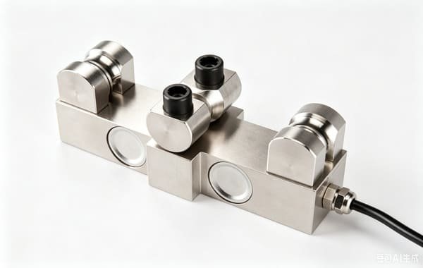
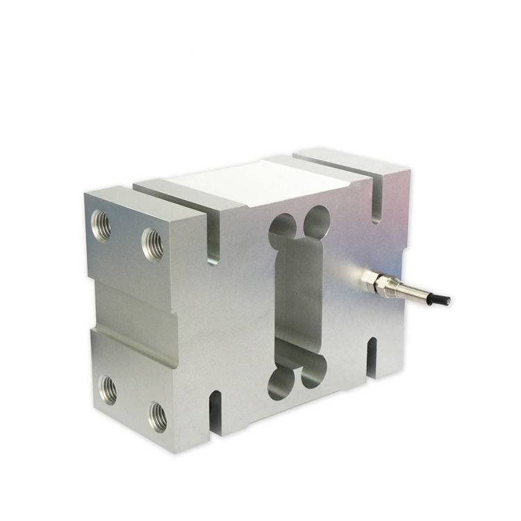
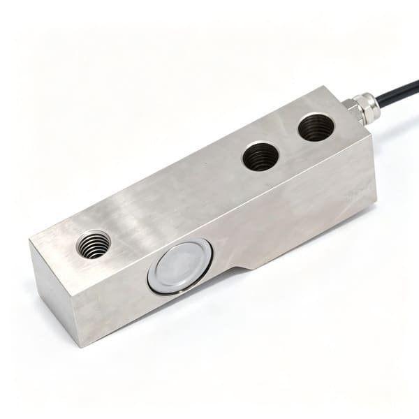
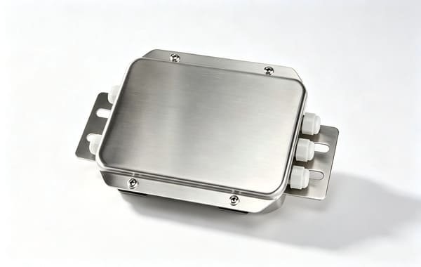
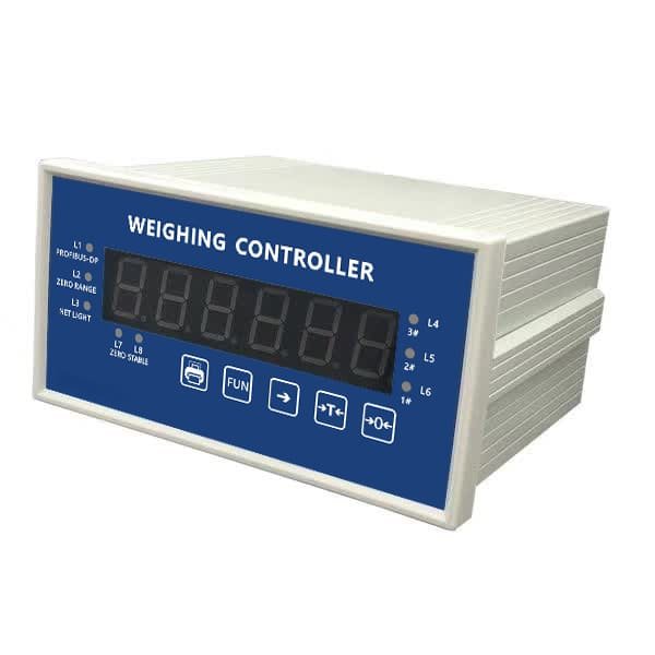
💡 Not sure which building blocks fit your machine? Send us a drawing, a photo of the load path, or just the questions above (Section 8) filled in. We’ll reply within 24 hours with a recommended sensor family — or a combination of cells, junction box and indicator — plus datasheets and a rough wiring scheme. If you need load testing gear for your fleet, ask about our wireless dynamometer load links too.
Let’s Spec Your Weighing Core Together
We’re a load-cell and weighing-instrument manufacturer and exporter — load cells, force sensors, junction boxes and indicators — not a lifting-platform builder. Since 2004 we’ve shipped sensing cores into Europe, the Middle East, the Americas and Southeast Asia. Tell us about your machine, the load path, the environment and the output your controller speaks, and we’ll recommend the right cells — or the complete cells + junction box + indicator chain — with datasheets, wiring guidance and test evidence to back it up. OEM / white-label supply welcome.
📩 Send us your load profile and we’ll reply within 24 hours.