
Load Cells for Forage Balers: The Bale Is One Sixth of the Machine
A round baler weighs 3,922–4,570 kg and the bale it makes weighs 500–1,000 kg. Almost every baler weighing project I have been asked to quote fails on that one ratio, not on the sensor. Add a PTO shaft that pushes the machine sideways, a bale chamber that is itself a hydraulic press, and a crop whose density moves by a factor of two, and the load cell becomes the least interesting part of the problem.
Whole-machine vs bale-only weighing
Dry matter against wet weight
ISO 11783 · OIML R107 · EU 2023/1230
1. “Baler” Is Four Different Weighing Jobs
The enquiry usually arrives as one sentence — “we need load cells for our forage baler” — and it can mean any of four machines, each with a different load path, a different accuracy requirement and a different answer.
A. Weigh the bale the machine makes — a load path that starts inside a bale chamber held closed by hydraulic pressure. B. Weigh the bale as it leaves — a chute, ramp or press exit that only ever sees the bale. C. Weigh the machine so the bale can be inferred from the difference — an onboard weighing problem, not a scale problem. D. Weigh the bale somewhere else entirely — a wrapper turntable, a yard weigh frame, a stacking table, the truck bridge at the buyer.
Which one you are in is decided by a single question, and it is not about accuracy. It is: is the number a measurement or a correlation? A measurement is traceable to a mass and stays true when the crop changes. A correlation is a signal that moved with weight once, on the crop the dealer had in front of him, and it is perfectly useful for keeping bales uniform and completely useless for sending an invoice. I will keep coming back to that line, because in this category it is where most of the money and every dispute lives.
It also matters which bale you are talking about, because the mass range is enormous. These are official extension-service figures rather than catalogue numbers, which is why I prefer them:
| Bale type | Typical mass | What that means for the sensor |
|---|---|---|
| Small square | 18–24 kg | Chute weighing with a small-range cell is realistic. Manual handling dominates the process. |
| 4×4 round, dry hay | 280–330 kg | The awkward middle. Light enough that tare noise hurts, heavy enough that no one wants to handle it twice. |
| 4×4 round, silage | 500–650 kg | Same dimensions as the row above, roughly 1.9× the mass. Section 8 is about why. |
| Big square (8×3×3) | 400–480 kg | Produced as a continuous flake stream. The chute is a natural weighing position, and it is where the machines in this class put their cells. |
| Large square (8×4×3) | 620–650+ kg | Distances are longer, densities are higher, and buyers want tonne figures. This is where billing pressure shows up first. |
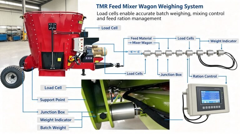
Two boundary notes before we start, because I would rather say them now than in a footnote. First: I am not a baler manufacturer and I am not going to become one in this article. Everything below is about the weighing part — where the load path is, what the sensing element sees, what the number can and cannot mean. Frame design, axle and drawbar engineering, the tailgate, the gearbox, the PTO driveline, the binding system, the machine’s own control software and the CE file are somebody else’s product, and I will point that out again at the end. Second: the nearest article I have already written is on TMR feed mixer wagons, and that is not an accident — a trailed mixer and a trailed baler are the same weighing problem with different crop in them. The mixer article covers the general trailed-machine rules; this one covers what is specific to bales: a payload that is a small fraction of the machine, a chamber that is a press, and a crop whose density and moisture move far more than its mass.
2. The Bale Is 18 % of the Machine That Carries It
Start with the numbers a commercial fixed-chamber round baler actually publishes. Machine weight with a wide pick-up and a full set of rollers: 3,922–4,570 kg. Bale: 500–1,000 kg for the large commercial class. Take the mid-points and the bale weighs 17.7 % of the machine that carries it — and 15.0 % of machine plus bale combined, which is the ratio that governs everything in Section 4. At the worst corner — a heavy machine, a light bale — those fall to 10.9 % and 9.9 %.
Now put a number on what that costs you. Suppose the commercial requirement is a bale weight good to ±0.5 %. On a 750 kg bale that is ±3.75 kg. If your sensing element carries the whole machine, then that 3.75 kg has to come out of a signal that is 4,246 kg tall. The whole machine must stay stable to 0.088 % — 883 parts per million, or one part in 1,132.
That is not an impossible number. It is a number that tells you what kind of problem you have. 883 ppm of 3,922 kg is ±3.5 kg on the whole machine, and the machine is standing in a field. So the useful question stops being “which load cell” and becomes “what weighs a few kilograms, is on this machine, and is not the bale”. Several things are:
| Thing on the machine that is not the bale | Mass | As a share of a 750 kg bale |
|---|---|---|
| 1 mm of rain on a 4 m² top surface | 4 kg | 0.53 % |
| A part-used net wrap roll, changed after the last zero | 20–30 kg | 2.7–4.0 % |
| Mud and crop carried on the frame after a wet pass | a few kg, and it sheds unevenly | the same order as the whole error budget |
| The pick-up resting on the ground instead of being carried | tens of kg, and it changes with every rut | larger than the whole allowance |
That last row is why every production machine that weighs bales does the same strange-looking thing: it lifts the pick-up off the ground before it weighs. The pick-up is a ground-following implement bolted to a weighing machine. Left down, it is an unknown share of the machine’s mass routed through the soil. Lifted, its mass is at least the same every time.
On a static platform scale you solve all of this with one press of a zero button on an empty machine. On a baler you cannot, because the machine is never empty in the sense that matters: there is always a bale forming, always a partial one, always a wrap roll, and always whatever the last hundred metres of ground did to the frame. The zero is the hard part, not the span.
If your load cells carry the whole machine, you are not weighing a bale. You are weighing a 4,246 kg machine to a tolerance of 883 ppm and then subtracting. Every method in Section 5 is really a different answer to “how do I stop doing that”.
3. The Noise Floor Is Already 15 kg
I do not have to argue about this from first principles, because it has been measured and published. A research group instrumented a round baler with a load cell in the drawbar coupling and strain gauges on the axle, sampled at 200 Hz, and logged the whole bale cycle in three states. What they found is the single most useful table in this field, and it is worth reading slowly:
| Machine state | Drawbar / tongue signal | Axle signal | As a share of a 750 kg bale |
|---|---|---|---|
| Parked, engine running, PTO off | ±15 kg, peaks to ±40 kg | ±20 kg | 2.0 % typical, 5.3 % at peaks |
| PTO engaged | variation increases further | a step change on one side — load shifting across the axle | a repeatable bias, not random noise |
| Driving | deviations over ±200 kg | deviations over ±400 kg | 27 % and 53 % |
| Driving, after a 500-point running average | still ±15 kg on the summed signal | — | 2.0 % |
Read the first row again. That is a machine that is standing still, making nothing, with a bale mass of zero, and the weighing system is already moving by 15 kg and peaking at 40 kg. The same study went further and checked the case where the answer should be exactly zero — driving the baler across a field with the pick-up up and no crop at all. Correlating the indicated mass against measured vertical acceleration, they found that in more than half of the cases in which vertical acceleration was zero, the indicated mass was correctly zero. Which is the polite way of saying that in close to half of the samples, the instrument was reporting mass that did not exist.
Notice what the error is made of. It is not strain gauge drift, and it is not the cell’s accuracy class. It is vertical acceleration. A load cell does not measure mass; it measures force along one axis, and force equals mass times acceleration. The calibration assumes the acceleration is gravity and only gravity. Every bump, every rotor imbalance, every tailgate thump writes itself into the reading as if it were kilograms. That is why the same group’s published paper reports two very different numbers for one machine: errors under 1 % in static tests, and residual errors of up to 10 % when weighing on the move after smoothing. Same sensors, same machine, same bales. The difference is whether the machine was moving.
There is one more detail in that data set that I want to flag, because it is the same failure I have written about on dairy equipment. When the PTO is engaged, the axle signal does not just get noisier — one side of the axle drops. That is the driveline torque reaction finding its way to the ground through the axle, and it re-routes load from one wheel to the other. It is not noise. It is a real, repeatable force, and it appears the moment the machine starts doing work. If your sensing element is anywhere in the path that torque travels through, you have made the torque part of your measurement.
A trailed baler is a vibrating, PTO-driven, ground-following structure. On a whole-machine load path you start with roughly ±15 kg of measurement noise before a single kilogram of crop arrives, and that is 2 % of a 750 kg bale. You do not get to design that away with a better sensor. You design around it — by choosing where the sensing element sits, and by choosing which seconds of the cycle you are willing to call a measurement.
4. Why the Tare Multiplies Every Datasheet by 6.7
Here is the arithmetic that decides most baler weighing projects, and it is one line long. A load cell’s accuracy is quoted as a percentage of its own full scale. But if that cell’s range has to span the whole machine, then its full scale is roughly the machine, and the number you actually care about is a small fraction of it. The ratio between them is the amplification factor:
(tare + payload) ÷ payload = (4,246 kg + 750 kg) ÷ 750 kg = 6.66×
Every %FS figure on the datasheet becomes 6.66× larger when you express it against the bale. Not because anything changed — because you moved the denominator.
| Cell on a whole-machine load path | Class | Error in kg | As a share of the 750 kg bale |
|---|---|---|---|
| WST708, 5 t pin cell | ±0.5 %FS | ±25 kg | 3.33 % |
| WST1406, 15 t onboard cell | 0.1 % | ±15 kg | 2.00 % |
| WST1404, 100 klb double-ended | 0.03 % | ±13.6 kg | 1.81 % |
| WST302, 5 t shear beam | 0.03 % | ±1.5 kg | 0.20 % |
Look at what happened in that table. Two cells with the same 0.03 % class land at 1.81 % and 0.20 % of the bale, purely because one of them had to be bought in a large enough range to hold up a whole machine. And the ±0.5 % cell — a perfectly respectable class for what it was designed for — is 6.7× outside a ±0.5 % target before anything else is wrong with the installation.
Turned around, the rule is easy to carry in your head. To land the bale at a given tolerance, the error class and the tare ratio have to multiply out to less than that tolerance, so each class comes with a maximum tare you are allowed to have standing on the cell:
| Cell error class | Maximum tare-to-payload ratio, for a 0.5 % bale | In plain words |
|---|---|---|
| 0.03 % | 16.7× | Comfortable. The bale can be a sixteenth of what the cell sees. |
| 0.05 % | 10× | Workable for a chute or a platform. |
| 0.1 % | 5× | A 4 t machine with a 750 kg bale is already over this. |
| 0.5 % | 1× | Effectively zero. The cell may only carry approximately the thing you are weighing. |
I want to be precise about one thing here, because it is a claim that gets made loosely. There is a family of methods that weigh the machine before ejecting the bale and again after, and subtract. Those methods are genuinely clever and they solve a real problem: anything that is constant across that shot — the machine’s own mass, a fresh wrap roll, yesterday’s mud, the exact zero — cancels out exactly. That is why one production baler can be advertised as calibration-free: the net wrap roll it just loaded cannot affect a subtraction.
But differencing does not reduce the 6.66× factor, and this is the part people miss. The cell still has to span the whole machine, so its error is still quoted against the machine, and the subtraction is of two numbers that are each wrong by that same amount. Two errors of the same size, subtracted, do not shrink — at best they cancel, at worst they add. Differencing removes tare drift and constant offsets. It does not remove scale error. Those are two different things wearing the same word.
The only way out of the 6.66× is to change what the cell carries. Put the sensing element underneath the bale alone, in a chute or on a weigh frame, and a cell you would never have considered suddenly becomes generous:
WST1404, 100 klb (45.4 t), 0.03 % class. Under the whole machine: 1.81 % of the bale. Under the bale only, on a 1 t range: 1.65 % utilisation, and the same error class becomes 0.04 % of the bale. Roughly a 45× improvement, achieved entirely by moving the sensing element 300 mm and changing nothing else.
That is why I keep saying the architecture is the specification. Two engineers can buy the same part number and land 45× apart, and the datasheet will not tell either of them which one they are.
5. Three Ways to Put a Number on a Bale
There are three families of solutions in production, and they differ in what the sensing element is allowed to see. Everything else is detail.
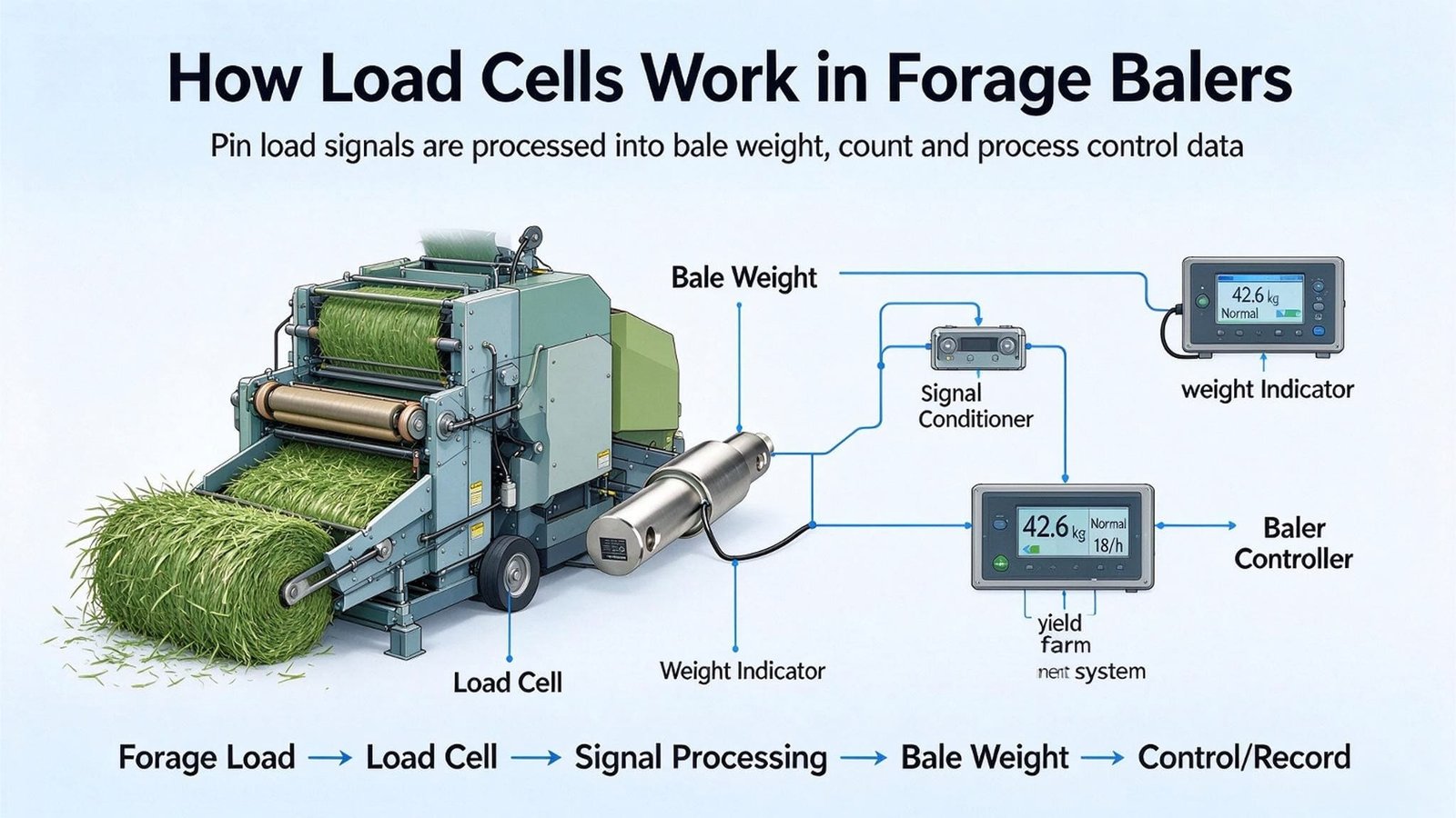
Family A — weigh the whole machine and subtract. Cells in the drawbar and instrumentation on the axle. This is the classic research configuration, and it is also what production machines use when they do it: one round baler on the market uses three weighing cells, lifts the pick-up hydraulically during the weighing step so its supported mass cannot pollute the reading, and compares the machine’s total weight before and after bale ejection. The difference is the bale. That design also explicitly solves the terrain problem by comparing two states rather than trusting an absolute number, which is how it can claim no recalibration.
The published performance is the honest headline for this whole family: a properly built system of this type reached under 1 % error in static tests and up to 10 % residual error weighing on the move. It also does not retrofit cheaply, because you usually cannot interrupt the load path without changing the axle or wheel spindle assembly and adding a load bar to the tongue.
Family B — weigh the bale and nothing else. Cells under the discharge chute, the press exit or an off-ramp, arranged so a formed bale passes over them or rests on them for a moment. This is the configuration that sidesteps Section 4 entirely: the cell’s full scale is chosen around the bale, so there is no tare to amplify anything. Industrially this is the family used on large and small square balers, where a plunger pushes a finished flake-stack out along a defined path. It is worth knowing that in the patent literature this arrangement is described as not known on round balers — a round bale rolls out of a tilting tailgate rather than being pushed along a chute, so there is no settled place to stand on.
Family C — infer the bale from something else. No cell in the load path at all; instead a signal that moves with bale mass. There are four variants in commercial use or in patents, and they are worth being able to recognise because they are frequently sold as “weighing”:
| Inference signal | What it actually measures | Published accuracy |
|---|---|---|
| Tailgate hook position | How hard the chamber is pushing the gate open — a chamber pressure signal, not a mass | Fine for density control; not offered as a bale mass |
| Displacement between the baling chamber housing and the axle | Frame deflection, which is force divided by the frame’s own stiffness | Around 2 % claimed, with a tilt correction for slopes |
| Hydraulic pressure at the bale kicker or push bar | The force needed to eject, which correlates with mass and with friction | Patented; claims under 15 %, typically 1–7.5 % average absolute error |
| Velocity or acceleration of a spring-loaded off-ramp | Momentum of the departing bale | Same patent family |
The interesting technical note in that displacement patent is that a round baler is the favourable case for it, because as the bale grows its centre of gravity does not change direction — so no drawbar load cell is needed at all. That is a real engineering insight. It is also exactly the point where an inference becomes fragile: the method assumes the frame’s stiffness is constant, and a frame’s stiffness is constant only until the crop, the temperature or fifteen years of work change it.
Ask one question: if I change crop from dry wheat straw to 50 % moisture grass silage tomorrow, what happens to the displayed weight? Family B gives the same answer, because it is a mass. Family C gives an answer that is wrong by however much the density changed — which Section 7 puts at tens of percent. Family A sits in between: it is a real measurement, but a noisy one, and it will be 2 % rather than 0.5 %.
6. The Weighing Window, and Why Filtering Cannot Rescue It
If the noise while driving is ±200 kg and the noise while parked is ±15 kg, then the most valuable design decision in a baler weighing system is not the cell and not the filter. It is deciding which seconds of the cycle are allowed to be called a measurement. Everything that follows is arithmetic on that decision.
A bale cycle gives you a budget. At 40–100 bales per hour, one bale takes between 36 and 90 seconds end to end. Inside that, there is a stationary window while binding and ejecting happen. A weighing window of 10 seconds is comfortable. Twenty is possible. Sixty is not, because it is the whole cycle and the machine has to keep making bales.
Noise from a random source falls with the square root of the number of samples averaged, so the window length converts directly into accuracy. Starting from the measured point — 500 samples leaves ±15 kg — here is what the window actually buys:
| Stationary window | Samples at 50 Hz | Residual noise | On a 750 kg bale |
|---|---|---|---|
| 5 s | 250 | ±21 kg | 2.8 % |
| 10 s | 500 | ±15 kg | 2.0 % |
| 40 s | 2,000 | ±7.5 kg | 1.0 % |
| 250 s | 12,500 | ±3 kg | 0.4 % — and longer than the whole bale cycle |
That last row is the answer to the most common request I get: can you filter it so it is accurate? To get to ±3 kg you need 12,500 samples, which at 50 Hz is 250 seconds, which at 100 bales per hour is seven bale cycles. The machine will have ejected seven bales and moved on. Filtering buys you a factor, and the factor is finite.
Two technical footnotes that make the table better than it looks and worse than it looks at the same time. Better: if you use a digital cell, the sample rate is a published number you can design against — one of our digital cells runs at 50 Hz on a 125 kbps CAN line with a single cell on the bus, or 20 Hz on 9,600 bps Modbus, and its specification lists the effect of cable length on system accuracy as zero, because the conversion happens at the cell. On a machine with long cable runs down a vibrating frame, that is worth more than a better accuracy class. Worse: the square-root rule assumes the disturbance is random and zero-mean. Acceleration from driving over ruts is a driven oscillation, not white noise, so the real gain from averaging is smaller than the table promises. I quote that table to explain the size of the problem, not to promise it as a result.
The practical output of all this is not a filter setting. It is a written state definition — the same thing I have argued for on bulk tanks and on feed mixers, and the same thing that in practice is almost never written down. Something like: “A weight is accepted only when the machine is stationary, the PTO state is defined, the pick-up is raised, the tailgate is in its closed detent, and the signal has stayed inside ±5 kg for at least 8 seconds. The display shall show whether the number on screen is a measurement or a last-known value.” Four lines of specification, and they usually decide whether the system works.
7. What the Number Means: Density, Moisture, Dry Matter
Everything up to here has been about getting a number you can trust. This section is about the harder question, the one that is almost never asked at the quotation stage and always asked six months later: a number that is right — right about what? Two things sit between a baler reading and a useful fact, and both of them are bigger than the measurement error we have just spent six sections on.
The first is density. Inside a bale chamber, volume is fixed by the machine. Mass is not. Bale density for round bales spans roughly 100–200 kg/m³ in baler specifications, and other industry tables put round bales lower still, at 70–100 kg/m³. The disagreement between those two sources is itself the point: this is not a tightly controlled material property, it is a process outcome.
Take a concrete chamber. A 1,300 mm diameter, 1,400 mm wide chamber holds 1.858 m³. Fill it at the low end of the density range and it holds 186 kg. Fill the identical chamber at the high end and it holds 372 kg. Same geometry, same machine, same number of turns of the same rollers.
| What you are inferring from | Spread you cannot see | Against a 0.5 % target |
|---|---|---|
| Chamber geometry, at 100–200 kg/m³ | 186–372 kg on one fixed volume → ±33 % | 67× too coarse |
| Chamber geometry, at 70–100 kg/m³ | 246–352 kg on a 3.52 m³ bale → ±17.6 % | 35× too coarse |
| Frame deflection between chamber and axle | Depends on stiffness, which varies with crop, temperature and age | ∼2 % when fresh, and drifting |
To get a mass good to ±0.5 % out of geometry you would have to know the density to ±0.5 %. The material offers you ±33 %. That is a gap of nearly seventy times, and no amount of electronics closes it. So the useful conclusion is not “geometry-based weight is bad” — it is much more specific than that:
Uniformity — making every bale out of the same field the same size and roughly the same density, which is exactly what the tailgate hook position is used for on a fixed-chamber machine. Operator feedback — telling the driver to steer left or right because the bale is building unevenly. Jam and blockage detection. All three are worth having, and none of them needs to be traceable to a kilogram. And then the number must stop. It must not be multiplied by a price.
There is one more consequence of this that is easy to miss and expensive in the field. A displacement or geometry signal is calibrated once, on the crop the technician had in front of him, and the calibration is stored as a constant. Move from dry wheat straw to corn stover, or from dry hay to grass at 50 % moisture, and you have changed the density — and therefore the calibration — by tens of percent on a machine that still reads to one decimal place. The instrument does not become less precise. It becomes less true. Section 11 is a case where that exact thing cost a contractor a season of arguments, and nobody had touched a sensor.
The second thing between a reading and a fact is moisture, and it is the bigger one. Take the same 4×4 round bale in the same chamber, once as dry hay and once as silage:
| Same bale, two crops | Wet mass | Dry matter | Water in it |
|---|---|---|---|
| Dry hay, 15 % moisture | 305 kg | 259 kg | 46 kg |
| Grass silage, 50 % moisture | 575 kg | 288 kg | 288 kg |
| Difference | +88.5 % (±270 kg) | +10.9 % (+28 kg) | +242 kg |
The silage bale weighs 88.5 % more than the hay bale. Only 10.9 % more dry matter came out of the field. Of the extra 270 kg on the machine, 241.8 kg — 89.5 % — is water. If your display shows kilograms, then in this pair of bales it is showing you water to almost nine parts in ten, and feed to one part in ten.
That leads to the arithmetic I would put at the top of any baler weighing specification. At 15 % moisture, one moisture point is worth 1.18 % of the dry matter in the bale. A genuinely good weighing system, holding the bale to ±0.5 %, moves the same dry matter by 0.5 %. So the moisture term is 2.35× larger than the weight term — the thing you cannot measure dominates the thing you can, by more than a factor of two.
That is not an argument for giving up on the weighing. It is an argument for knowing what the weighing is for. If the number is going to be multiplied by a price per tonne, then a tonne of bale is not a tonne of feed, and the specification needs a moisture input — a hand-held meter, a lab sample, or a moisture sensor on the chamber — or the contract needs to be written per bale rather than per tonne. I have watched a version of exactly this argument go on for a whole season, and Section 10 is that story.
One last piece of field arithmetic that belongs with this, because it decides whether baling wet is even worth it: published work from the forage extension services puts dry matter loss at roughly one percentage point for every percentage point the bale dries down after baling. A bale put up at 20 % moisture and dried to 12 % has lost about 8 % of its dry matter — on a bale holding 244 kg of DM, that is 19.5 kg of feed, the equivalent of 24 kg of wet bale at 20 %. Which is to say: the sensor cannot fix moisture, and moisture is where the money in this category actually is.
8. PTO Reaction, Impact, and How to Pick a Range
Section 3 ended with a number I did not explain: with the PTO engaged, one side of the axle drops. That is worth a paragraph of its own, because it is the difference between a problem you can average away and a problem you cannot.
A baler’s driveline spins at 540 rpm and transmits the torque that runs the rotor, the chamber rollers and the plunger. Every newton-metre you put into that shaft has to come back out somewhere, and on a trailed machine it comes out through the gearbox mounts and the frame into the axle, the tyres and the drawbar. That reaction redistributes load between the two wheels and the tongue. It is a real force with a direction and a magnitude — not a disturbance. Its only useful property is that it is repeatable: for a given crop, a given density and a given engine speed, it is the same force every time.
You have two choices with it. The clean one is to keep the sensing element out of the path the torque travels through — which is another way of saying weigh the bale somewhere the PTO is not. The second-best one is to define the PTO state, so the bias is at least the same number each time you accept a reading. What you cannot do is average it out, because averaging removes random variation and this is not random.
The second force nobody puts in the specification is impact. A bale is not lowered onto anything. It is ejected, it is tipped, it is dropped onto a ramp, it is picked up by a loader and it rides on a trailer at 40 km/h across a headland. Each of those writes itself into the load cell as a multiple of the static load, and the datasheet number that governs is not the rated capacity — it is the safe overload.
Put numbers on it. On the worst case in Section 2 — bale over the axle, one cell per side — each axle cell carries about 1,967 kg standing still. Now add vertical acceleration, which is what a trailed machine spends its whole working life generating:
| Vertical acceleration | Apparent load on that cell | As a share of a 5 t cell |
|---|---|---|
| 0 — parked | 1,967 kg | 39 % |
| +0.25 g | 2,459 kg | 49 % |
| +0.50 g | 2,951 kg | 59 % |
| +1.00 g | 3,935 kg | 79 % |
A 5 t cell that looked comfortable at 39 % is at 79 % of its rated capacity at one g, and one g vertical on a trailer crossing a rutted headland is not an exotic event — it is Tuesday. Rated capacity is the load you intend. Safe overload is the load that happens.
Take the heaviest static load the cell will ever see, add the worst dynamic event you can honestly imagine, and check that sum against the safe overload — not against the rated capacity. If the datasheet does not publish an ultimate overload, you cannot finish the second half of the check, and “not published” is not the same as “not relevant”.
Run the same 1,967 kg through the cells we actually quote, and the pattern is not the one most people expect:
| Cell | Rated | Safe / ultimate overload | Headroom over the static load | Vertical g it tolerates |
|---|---|---|---|---|
| WST708 | 5 t | 120 % / 150 % | 3.05× / 3.81× | 2.05 g / 2.81 g |
| WST302 | 5 t | 150 % — no ultimate published | 3.81× | 2.81 g |
| WST1406 | 15 t | 200 % / 300 % | 15.25× / 22.87× | 14.3 g / 21.9 g |
| WST1404 | 100 klb (45.4 t) | 140 % / 200 % | 32.28× / 46.11× | 31.3 g / 45.1 g |
Now read that table against Section 4 and the trade-off appears. The cell with the best accuracy class in our range, WST1404 at 0.03 %, is also the one with the most overload reserve — but only because it is a 45 tonne part. The accuracy class and the overload class are two different specifications, and they are not correlated. A 0.03 % cell rated 120 % safe overload is a worse choice in a bale-ejection path than a 0.1 % cell rated 200 %, because the failure mode of a cracked elastomer bonding is not a 0.3 % error. It is no reading at all. On a machine that gets shock-loaded every forty seconds for ten seasons, I would rather sell you the coarser part.
The last selection axis in this section is the environment, and for forage it is unusually punishing. Silage leaks acidic juice. The cell sits under a chamber that is washed, hosed, or left wet for months. Where a cell is going to live in that, a hermetically welded IP68 body is not a luxury — our WST1404 is welded and rated IP68, against IP67 for the sealed-but-not-welded WST708. On the PTO side of the machine, where the cell is a pin in a dry structural joint, IP67 is the honest answer and you should not pay for more.
There is one inherited rule I want to pass on, because it came from the feed-mixer side of this market rather than the baler side, and it has held up every time I have checked it: on trailed machines, prefer a round-bar bending-beam construction over a conventional shear beam, because repeated shock on a bonded elastomer is what kills cells in the field, and a pothole does not care what the datasheet said. Where a customer insists on a shear beam on a trailed chassis — and there are good reasons to — the mounting has to give the cell a defined, non-shock load path, and that is a frame design task, not a sensor task. That division of labour is the whole point of the feed-mixer article, and it applies here without a single change.
9. Case: the 14 kg That Arrived Before the Bale
The first project I want to describe did not involve me selling anything, and I think that is why it is worth telling.
A baler manufacturer in Wielkopolska, Poland builds a trailed fixed-chamber round baler — around 4.1 tonnes, a 1.2 m by 1.5 m chamber, hydraulic tailgate. They had already fitted weighing hardware from another supplier: four 5 t pin cells, one in the drawbar and a pair at the axle, feeding an indicator in the cab. Their email to me was one sentence long and slightly annoyed: “our display already shows 14 kg before the first bale, and it drifts through the day.” They wanted to know whether our cells would fix it.
The first thing I did was not quote anything. I asked for the load-path drawing, and a phone video of one complete weighing step from the cab. What came back changed the diagnosis completely.
The machine was showing 14 kg because it was 14 kg heavier than it had been when somebody pressed zero. Not because the cells were wrong. Three things had changed since that zero, and all three of them were on the machine:
- A part-used net wrap roll had been fitted after the zero was set — worth 20–30 kg.
- The machine had spent two days in the rain. At 1 mm per 4 m² of top surface, that is 4 kg per millimetre of standing water, and it sheds unevenly.
- The pick-up was still resting on the ground during the weighing step, so an unknown share of the machine’s own weight was going into the soil through the flotation rather than through the cells — and that share changed with every rut.
Which is how you can arrive at a 14 kg offset with nothing broken: roughly 24 kg of wrap roll and rain added, minus roughly 10 kg of machine weight quietly leaking to the ground through the pick-up. The instrumentation was reporting the truth. The zero was the thing that had stopped being true.
What I proposed instead of a quotation
I wrote them four lines of specification and asked their controls engineer to implement them, and I will reproduce them here because they have been useful on every baler and mixer since:
A weight is accepted only when the machine is stationary; the pick-up is fully raised; the tailgate is in its closed detent; the PTO state is as specified; and the signal has stayed inside ±5 kg for at least 8 seconds. The zero is re-established inside that window on every cycle, not once per session. The display must show clearly whether the figure on screen is a measurement or a last-known value.
The change from a session zero to a per-cycle zero is the part that actually solved their complaint. On a static platform scale the wrap roll is irrelevant, because you zero before every weighing. A baler has no empty state — there is always a partial bale, always a wrap roll, always the last hundred metres of ground — so the only honest zero is the one taken inside the same physical state as the measurement.
What it changed, and what I refused to sell
After the rewrite the offset disappeared by construction, and bale-to-bale repeatability came in at roughly ±5 kg on a 750 kg bale — a little under 0.7 %. That is a long way from the ±0.5 % that a billing application would need, and I said so plainly: this is a good operator display, and it is not an invoicing instrument.
They asked whether moving to a 0.03 % accuracy class would get them to ±0.5 %. I told them no, and I said it knowing it was the sale I was being handed. Section 4 is the reason: on a whole-machine load path the tare multiplies every datasheet number, so a class change moves them by a kilogram or two, while the ±15 kg noise floor from Section 3 does not move at all. Selling them a better cell would have made my quarter and cost them a season. They kept the cells they had.
What we did quote, six months later, was the sensible next step: a chute weighing option using WST302 on a small-range load path where the cell sees the bale and nothing else. That is the only configuration in which their ±0.5 % requirement is reachable, and it is reachable because of where the sensor sits rather than how good it is.
When a customer’s complaint has a mass in it — “it reads 14 kg heavy”, “it reads 30 kg light” — the diagnosis is usually a zero problem, not an accuracy problem, and the fix is a written measurement state rather than a part number. When the complaint is “it wanders”, that is the architecture talking, and the answer is Section 5.
10. Case: the “Weight” That Was a Length
This one cost somebody a year of arguments, and it is the reason I keep hammering on the measurement-versus-correlation question.
A custom baling contractor in Córdoba, Argentina bales cereal straw for a biomass buyer. His baler displayed a figure per bale in kilograms, and he invoiced off it. Over one season he billed 4,800 tonnes. The buyer’s weighbridge, when the trailers arrived, added up to roughly 7 % less. On paper that is 336 tonnes of straw — at 300 kg a bale, 1,120 bales — that one side thought existed and the other side could not find.
He came to me convinced his load cells were drifting, and asked for a set with a better accuracy class. So I asked him the question that should be asked first in every one of these enquiries: what sensor is producing the number?
The answer was that there was no load cell in the machine at all. The “weight” came from a displacement signal on the frame, multiplied by a density constant that had been stored during a calibration run. It was a length, scaled. Which means it was a correlation, not a measurement — and Section 7 tells you what that costs: the spread in bale density is tens of percent, so the constant was right on the day it was entered and gradually became a fiction as soon as the material changed.
And the material had changed. Mid-season he moved from dry wheat straw to a wetter, denser material, and the bales got heavier at the same shape. The instrument kept reporting to one decimal place the whole time. It had not become less precise. It had become less true — and there is no error message for that, which is precisely what makes it dangerous. A drifting load cell announces itself. A stale calibration constant does not.
“If I change crop tomorrow — dry straw to 50 % moisture grass — what happens to the displayed weight?” A measurement answers: the same. It is a mass, and mass is mass. A correlation answers: it depends on how much the density moved — which Section 7 puts at tens of percent. Ask this before you ask about accuracy class. It is a more decisive question.
What I recommended, and why it was not cells in the baler
Three things, in order:
One. Stop invoicing off the display. Not because it was useless, but because it was being asked to do a job it had never been built for.
Two. Keep the display, and change its job. Uniformity, operator feedback and jam detection are all things a geometry signal does genuinely well. Those uses cost nothing and they are worth having. The rule I gave him was blunt: the number can be precise, but it must not be multiplied by a price.
Three. Put the money where the money changes hands. Where the transaction happens is the yard, not the field — so the correct instrument is a static weigh frame he can drive a bale trailer onto, or roll a bale onto with the loader. Four shear-beam cells on a 1 t range, a stainless junction box with trim potentiometers for corner correction, and an indicator with a printer so the ticket prints where the bale is. The arithmetic is almost embarrassing: 0.03 %FS on a 1 t cell is 0.3 kg, and even if you add all four cells’ errors worst-case, 1.2 kg is 0.4 % of a 300 kg straw bale — inside the tolerance he had originally asked me for, achieved with the cheapest architecture in this article, on a frame that does not move.
The honest ending
He did not buy anything that season. He had already spent the year’s budget on the argument, and the frame needed designing by somebody local. He came back before the next season and bought the frame, the junction box and the indicator — not cells in the baler, and not a better accuracy class, both of which he had originally asked for.
I think about this case more than any other in the series, because everything I did right was unglamorous. A weigh frame is boring. It is cheap, it is static, it is calibratable with a known mass, and it is the only place in the whole forage chain where a tonne of bale is a tonne of anything. Nobody advertises it, because there is no story in it — and the reason I write it up here is that the story is exactly the absence of one.
11. Case: the Retrofit I Would Not Sell as Billing-Grade
The third case is the one where I did sell something, and where saying no to part of the enquiry is what made the rest of it work.
A manufacturer in Upper Austria builds trailed bale wrappers and the bale trailers that go with them. They had three questions in one email, and they are the three questions I get most often in this category: can we weigh the bale on the wrapper; can we also put cells in the baler so the weight travels with the bale; and would any of it be legal for invoicing customers?
The answer to the first question is easy: a wrapper is the best place in the chain
I told them to stop thinking about the wrapper as a secondary application, because on every criterion Section 4 and Section 8 care about, the wrapper wins. The bale is off the machine and separated from the tractor. It sits still for 20–40 seconds while the film goes round — a weighing window that no baler can offer. There is no PTO torque path through the platform, so the repeatable bias from Section 3 does not exist. And the load path contains the bale and nothing else, so the tare ratio that multiplies every datasheet number is not 6.66× — it is close to 1×.
Put together, that means an accuracy class you would never dare specify on a baler becomes comfortable on a wrapper. We quoted WST302 shear beams on a 5 t range under the loading ramp: 0.03 %FS is 1.5 kg, which is 0.2 % of a 750 kg bale, at only 15 % utilisation — so there is reserve in the cell for the moment the bale is dropped onto the ramp rather than lowered onto it. That is a bale weight that meets the tolerance people think they need a baler-mounted system to reach.
The answer to the second question was no, and to the third question a longer no
They wanted cells in the bale chamber as well, so that the weight was known before the bale left the baler. I argued against it and we did not do it. Everything in Sections 2, 3 and 8 applies: a chamber is a hydraulic press, the cell would sit in the torque path, and the tare would be a whole machine. Their own chamber signal — the tailgate hook position they already use for density control — does the job that feature actually needs, which is telling the operator that the bale is building as intended. Adding cells would have bought them a number that looks like a mass and behaves like a pressure, and it would have been worse than what they already had, because at least the hook position does not pretend.
The third question is the one I want on the record, because it is where I stop being a supplier and become a person telling you not to buy something.
A load cell can hold an OIML R60 pattern approval, and ours do where the datasheet says so. That approval is for the load cell as a component. Weighing something in order to charge money for it is regulated at a different level, on the instrument and the machine — OIML R76 / EN 45501 for a non-automatic instrument, MID 2014/32/EU (Annex MI-006) to place that instrument on the EU market, and the automatic-instrument categories such as OIML R107 where the instrument totalises discontinuous loads. None of those certificates can be inherited from the cell, and none of them can be issued by me. They are a notified body’s assessment of somebody’s machine, and that somebody is the OEM.
So I said: I will supply the components, I will supply the per-cell matching data and the raw test figures, I will help you design the load path and write the weighing-state definition — and I will not sign a declaration that this machine is fit for trade use, because I would be lying if I did and it would be your name on the CE file anyway. That is not modesty; it is the boundary of what a component supplier can honestly attest to. The same boundary applies to the new machinery regulation: EU 2023/1230 applies from 20 January 2027, and the conformity file for a baler or a wrapper will be built by the people who design it. A load cell changes nothing about that route.
One practical note in the same vein, because it came up: they wanted the weight on the tractor’s ISOBUS terminal. ISOBUS (ISO 11783) does not define a weighing function the way it defines, say, a rate controller — in practice the number travels to the terminal as a process value you define yourself, and ISOBUS conformance is certified for the implement as a whole under the AEF scheme, not for the load cell. Design the cell and the electronics around your own implement certification, not the other way round.
What we actually built, and the arithmetic behind each choice
Two systems went out, and the reason each part was chosen is the useful part of this story:
| Where | What we supplied | Why that one | Resulting error |
|---|---|---|---|
| Wrapper loading ramp | WST302, 5 t, 0.03 % | Bale-only load path with impact reserve; 15 % utilisation leaves room for the drop | 1.5 kg = 0.2 % of a 750 kg bale |
| Bale trailer deck | 4 × WST1404, 10 klb, 0.03 % | Structural beam in a welded IP68 body with 140 % safe overload for loading shocks | 5.4 kg on 6 t = 0.09 % |
| Junction box | WST1513 stainless, 4/6/8 channel | Trim potentiometers for corner correction on a rectangular deck; anti-surge on a 12 V machine | — |
| Baler side (declined) | WST708 pin cells quoted, not fitted | A pin cell replaces an existing hinge pin, so retrofit needs no frame redesign — the best option if they ever do it | — |
Two numbers from that table deserve a sentence each, because they are the same lesson from opposite ends. The trailer deck lands at 0.09 % on six tonnes of bales — an excellent result — and would be only about 0.7 % on a single 750 kg bale, because the four cells’ worst-case errors do not get smaller when the load does. That is the whole argument for matching instrument to job: the same hardware is superb for a load and mediocre for a bale. And the WST708 is the opposite kind of good: a poorer class at ±0.5 %FS, but it is the only one of these parts that can be threaded into a hinge point where a pin already goes, which on a retrofit is worth more than two decimal places.
12. The Selection Worksheet
If you take nothing else from this article, take these eight questions. I ask them in this order, and the answer to each one eliminates options before the accuracy class is ever discussed — which is why the last question is last.
| # | Question | Why it decides something |
|---|---|---|
| 1 | Is this a measurement or a correlation? | Decides whether you need a load cell at all. If a length or a pressure is doing the job, say so and stop — nobody should sell you cells to replace arithmetic. |
| 2 | What does the cell carry — the bale, or the machine and the bale? | Sets the tare amplification. 6.66× or close to 1× changes every number downstream. |
| 3 | What tolerance, in kilograms, and against what reference? | A percentage means nothing until you name the denominator — bale, machine, or season. The three give different answers. |
| 4 | Heaviest static load on the cell, worst case? | Usually not what you think. On a baler it is the bale over the axle; on a trailer it is the full deck plus the loader’s push. |
| 5 | Worst dynamic event, in g? | Checked against safe overload, not rated capacity. See Section 8’s one-line rule. |
| 6 | Cycle time and stationary window? | Converts directly into achievable accuracy. A wrapper’s 20–40 s is worth more than any accuracy class. |
| 7 | Environment: leachate, washdown, road salt, grit, cable run length? | Picks IP67 against hermetically welded IP68, and picks whether you need a digital cell with conversion at the cell. |
| 8 | Who consumes the number — operator, farm software, or an invoice? | If the answer is “an invoice”, stop and read Section 13 before buying anything. The accuracy class is the last decision, not the first. |
“Bale mass range ___ to ___ kg. Load path contains [bale alone / machine + bale]. Required tolerance ___ kg. Heaviest static load per cell ___ kg. Worst dynamic event ___ g. Weighing window ___ s, machine state ____ during the window. Environment ____. The number is used for ____. Please state, for each cell you propose, the rated capacity, the safe overload, the ultimate overload, the accuracy class, the IP rating, and the approval it holds — and tell me which of those five is the limiting one for my application.”
That last sentence is the one that separates suppliers who have thought about your machine from suppliers who are reading a catalogue to you. I have answered it in writing for customers who then bought elsewhere, and I have never regretted it.
13. What I Supply, What I Do Not, and Who Owns the Paperwork
I am a weighing component supplier. I am not a baler manufacturer, not a wrapper manufacturer, and not a system integrator, and I am not going to describe myself as one in order to win a project. That boundary will cost me some enquiries in this category, and it is the only honest way to write this section, because a baler is a machine with a CE file, a hydraulic system, a driveline and a safety case — and none of that is mine.
| What I supply | What I do not supply |
|---|---|
| Load cells: shear beam, double-ended shear beam, pin and double-shear pin, single-point, weighing modules | The baler, the wrapper or the trailer as a machine |
| Junction boxes with trim potentiometers for corner correction, stainless, 4/6/8 channel | Frame, axle, drawbar, chassis and bale chamber design |
| Indicators and controllers, including a stainless unit with a built-in ticket printer | Hydraulics, binding systems, PTO drivelines, tailgate mechanisms |
| Digital load cells on CANopen and RS-485 Modbus, conversion at the cell | Your machine’s control software, terminal application and ISOBUS/AEF implement certification |
| Per-cell output figures and matching data, so you can do corner correction instead of buying matched sets | CE marking and the machinery conformity file under EU 2023/1230 |
| Custom pin geometry to replace an existing hinge pin | Instrument-level metrological approval for trade: OIML R76, EN 45501, MID 2014/32/EU |
| A review of your load path and a written weighing-state definition | Moisture measurement, yield mapping and the telematics platform around them |
1. Our load cells hold component-level approvals — OIML R60 where the product page states it — and we work to ISO 9001. A component certificate is not an instrument approval, and I will not present it as one.
2. We do not hold baler or wrapper OEM approvals, and I will not claim our cells are inside a machine they are not in.
3. If your requirement is billing-grade, the cheapest correct route is usually a static weigh frame or the buyer’s existing bridge, not cells inside a bale chamber. I will tell you that even when it makes the order smaller.
4. Trial orders are welcome. We do not promise free samples — these are dimensioned, individually tested parts, and pretending otherwise wastes your time and mine.
What I am genuinely good at is the part in the middle: given your load path, your bale mass range and your tolerance, telling you which architecture can reach it, which cell in that architecture is the limiting component, and what the installation has to do so that the number stays true in year three. That is a weighing solution. It is not a machine solution, and I would rather be clear about that than win the enquiry.
14. Questions I Get From Baler Builders
Can I get ±0.5 % bale weight with load cells mounted on the baler itself?
Only if the cells carry the bale alone. If they carry the machine and the bale, the tare ratio is about 6.66×, and a published measurement on exactly that configuration found roughly ±15 kg of residual noise while the machine was stationary — 2 % of a 750 kg bale — before any accuracy-class error is added. ±0.5 % is 3.75 kg on the same bale, about four times smaller than the noise floor alone. Where ±0.5 % is reachable is a bale-only load path: a chute, a ramp, a wrapper platform or a static weigh frame.
My baler scale shows a few kilograms before the first bale. Is the load cell drifting?
Almost always no. That reading is usually a real mass the zero does not know about. A part-used net wrap roll fitted after the zero is worth 20–30 kg; rain adds about 4 kg per millimetre over 4 m²; a pick-up still resting on the ground quietly exports an unknown share of the machine’s weight into the soil. The fix is not a better cell — it is re-establishing the zero inside the weighing cycle, with the same machine state as the measurement, and lifting the pick-up before weighing.
Do I need a 0.03 % accuracy class load cell for a baler?
Only if the cell’s range is chosen around the bale. Accuracy classes are quoted against the cell’s own full scale, so on a whole-machine load path the class is divided by the tare ratio: a 0.03 % cell at 45 t range still contributes 13.6 kg, which is 1.81 % of a 750 kg bale. The same class on a 5 t cell under a bale-only load path contributes 1.5 kg, or 0.2 %. The architecture decides the number; the class only fine-tunes it.
Can load cells be retrofitted to an existing round baler?
Mechanically, yes, and the cheapest route is a pin-type cell that replaces an existing hinge or shear pin, so no frame redesign is needed. But a retrofit into the axle or drawbar inherits the whole-machine load path and its ±15 kg noise floor, so it can be a good operator display and it will not be an invoicing instrument. If the requirement is accuracy, retrofit the weighing position — a chute, a ramp or a yard weigh frame — rather than the machine.
How many load cells does a baler weighing system need?
Three or four on a whole-machine system: typically one in the drawbar coupling plus a pair or a group at the axle, arranged so the supported mass is fully captured and the pick-up does not fight the cells. On a bale-only load path, two cells under a chute or four under a rectangular platform or trailer deck, which also lets you do corner correction with a junction box that has trim potentiometers.
Does a baler weighing system need recalibrating every season?
A real load-cell system with a defined weighing state should not drift, because a cell measures force directly. What does go stale is any system whose number comes from a geometry or pressure signal multiplied by a stored density constant: move from dry straw to wet grass and the constant becomes wrong by tens of percent while the display still reads to one decimal place. The instrument does not become less precise, it becomes less true — and there is no error message for that.
Can I use a baler load-cell system to bill customers per tonne?
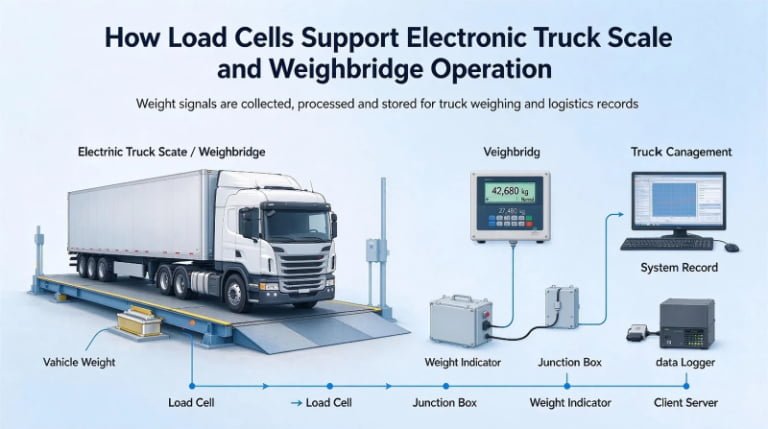
Not off a chamber-mounted system, and not off any system whose cell carries the machine. Weighing for trade is regulated at instrument and machine level — OIML R76 and EN 45501 for a non-automatic instrument, MID 2014/32/EU for placing it on the EU market, and the automatic totalising categories such as OIML R107 — and a load cell’s OIML R60 approval is a component approval that cannot be inherited. The practical route is a static weigh frame or the buyer’s existing weighbridge, with the machine-mounted reading used for uniformity and operator feedback.
Which of your load cells fits which position on a baler?
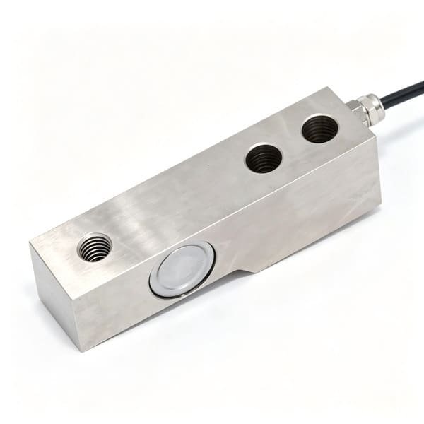
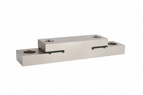
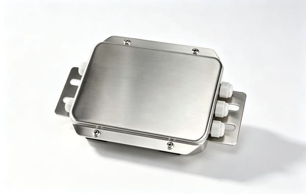
Three answers, by load path. WST708 is a pin-type double-shear cell (5 t and 7.5 t, ±0.5 %FS, IP67, all-stainless) for the drawbar and axle group, and its practical advantage on a retrofit is that it replaces an existing hinge pin. WST302 is a shear beam from 0.05 t to 20 t at 0.03 %FS for chute, ramp and weigh-frame positions where the cell sees the bale alone. WST1404 is a double-ended shear beam from 2.5 klb to 100 klb, 0.03 %, in a hermetically welded IP68 body with 140 % safe overload, for bale trailer decks and structural load paths that take impact. Add WST1406 where the machine travels with its load, and a WST1513 stainless junction box wherever there are four cells to trim.
Recommended Models
The five parts below cover every load path described in this article. Ranges are per model; if none of them brackets your bale mass and tolerance, tell me the numbers from Section 12 and I will tell you honestly whether we have something that fits.


Tell me your bale mass range, the load path the weighing element sits in, and the tolerance you actually need — and where the number is going to be used. I will tell you which architecture can reach it, which cell is the limiting part, and if the honest answer is a static weigh frame instead of sensors on your machine, I will tell you that too.