
Shackle Type Load Cells for Aquaculture: The Line Has No Tare
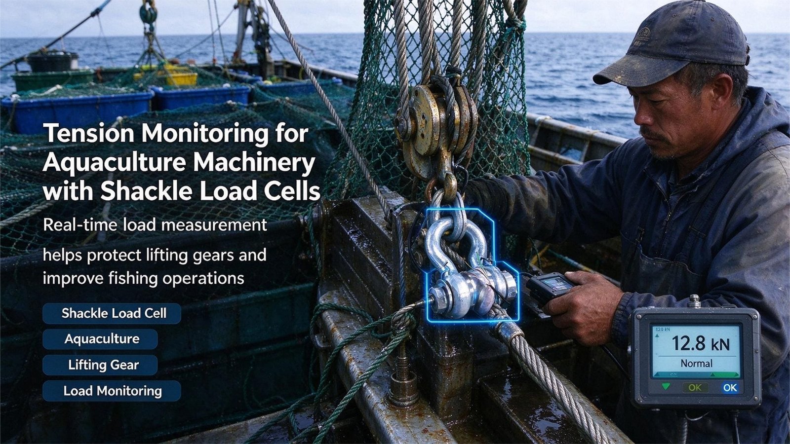
Every weighing job I had quoted before this one arrived with a platform, a tare key and something that sat still while I zeroed it. A mooring line has none of those. Its geometry changes with the tide, its mass grows all season, and its load spends ninety-one days looking calm and under five seconds deciding whether a fish farm becomes an escape report. A shackle type load cell for aquaculture equipment is also the one product on a site that replaces a certified component instead of adding a new one, and that single fact decides how it has to be specified. I have quoted these into four countries now, and the three builds below — Hitra, Chiloe and the Faroe Islands — each turned on a number that was in the specification sheet all along and was never the accuracy line.
Shackle Type Load Cells for Aquaculture Equipment: Three Jobs, Only One of Them a Line
Two companies publish enough about this work for me to describe the whole job without guessing. Sematek, on the Norwegian coast, spent more than forty years testing and inspecting floating marine structures and aquaculture installations before they sold instrumentation: shackle cells that read and log continuously to 100 tonnes, mounted on the mooring components of floating structures, recording loads that are either environmental or vessel-generated, and pushing the data out through their own software or an API. Innovex, in Puerto Montt, comes at it from the other end. They make the oceanographic instruments — oxygen, temperature, salinity, currents, waves and weather, plus a 3 100-litre buoy that is their twenty-first — and the DataWeb platform behind them, across a footprint their own site counts as 236 online sea sites, 885 anchorages in Chilean regions X, XI and XII, 3 130 live sensors, 1 200 automated ponds and 520 seawater cages.
Put the two together and you have the complete picture of what measuring load on a fish farm means. One company turns a shackle into an instrument, the other turns an instrument into a subscription, and neither sells you a fish farm, nor should they. What I do sits underneath both: stainless steel load cells, junction boxes and indicators, in the sizes and ingress ratings that go on a site where the salt water arrives every twelve hours and nobody is going to walk out and wipe the connector.
On a farm a shackle type load cell for aquaculture equipment turns up in three places, and they are not variations of one job. They are three different jobs that happen to use the same catalogue.
| The job | Where the cell sits | What it actually reports | What it cannot tell you |
|---|---|---|---|
| The line | In a mooring leg, a bridle, a hoist pennant or a tow line | Axial tension in that one leg, in newtons | Whether the other seven legs are doing their share |
| The node | Between a barge, a davit or a winch and whatever holds it | The pull a vessel or a silo puts into the structure | Where along the barge that pull is actually reacting |
| The deck | Under a sample bin, a mortality bin or a feed sample tray | Mass, the ordinary way, on a platform that does not move | Nothing. This is the one job you can audit with a kitchen scale |
| The boundary | A price is computed from none of these readings | So no trade-metrology regime applies to any of them | A safety regime does, and it is not mine to sign — see chapter 6 |
The line: four hundred tonnes of water moving past a net
A standard Norwegian sea cage is specified by circumference, and 120 m is the common number: a diameter of 38.2 m, which with a net 15 m deep is about 2 946 square metres of netting. The sinker tube hanging at the bottom — HDPE pipe filled with chain, anywhere from 15 to 140 kg per metre depending on the site — weighs 4.8 tonnes at 40 kg/m. Fill that volume at 15 kg per cubic metre and you have roughly 220 tonnes of fish.
Here is the part that took me a while to internalise. Those 220 tonnes of fish are, to the mooring, almost nothing: they are the payload and the reason the site exists, and they are nearly the density of the water they swim in, so they contribute almost no load to the lines holding the cage on station. What loads the grid is water moving past the net. At 0.5 m/s and a drag coefficient of 1.0, a clean net of that area produces about 377 kN, which is 38.5 tonnes, on one cage. Put eight cages on a shared grid with a barge and you have a structure whose design case is almost entirely hydrodynamics, plus one 4.8-tonne chain in every net pulling down on the bottom of the enclosure.
Now foul the net. Published biomass figures for salmon netting run from about 2 kg per square metre after eight weeks of immersion in New Zealand water, to 4.9 kg per square metre on an untreated panel after ten months in Shetland, against 1.8 kg per square metre on a coated panel over the same period. Two kilos per square metre on 2 946 square metres is 5.9 tonnes of added submerged mass on one cage, and a typical Norwegian farm carries something like 50 000 square metres of submerged structure, so the farm-wide figure is in the order of 100 tonnes at the low end. Worse than the mass is the drag: the hydrodynamic force on a fouled net has been calculated at up to 12.5 times that of a clean one, and more recent work puts it at up to ten-fold.
That is the whole reason a load cell belongs in a mooring leg. The design already allows for the fouled case; the mooring analysis is built from ten-year and fifty-year maxima of current, waves, wind and ice, and it assumes a net that has been in the water for weeks. What nobody at the site knows is where on that range they currently are. On 12 March that site was at 68 % of the design and on 12 August at 94 %, in the same weather. The difference was the net.
Two hundred and twenty tonnes of fish hang on this mooring and add almost nothing to it. Six tonnes of fouling add six, and the water multiplies both.
The node: the biggest loads on a farm are usually not from the sea
Sematek’s own product description splits the recorded load into two kinds, environmental and vessel-generated, and that split is the most useful sentence I have read from anyone in this business. A feed barge is a 40-metre floating building. Run the windage calculation on a 40 by 4 metre superstructure at 25 m/s with a drag coefficient of 1.2 and you get 73.5 kN, or 7.5 tonnes of side force. Add the hull in a 1 m/s current, 40 metres by 3 metres of draft, and you get another 61.5 kN. Together that is about 13.8 tonnes of steady environmental pull on a structure whose lines are rated in tens of tonnes.
Then a service vessel ties up to it. A 40-metre workboat lying alongside in a 1.5 m swell with two spring lines, engines holding station, sending feed or collecting mortality, will put transients into those lines that are larger than anything in a moderate gale, and it will do it twice a day instead of twice a decade. This is the load that will never appear in a wave analysis, because it is not a wave. It appears in your data if you are recording properly, and the whole discussion of chapter 2 is about the fact that most people are not.
The deck: the only job here you can check with a kitchen scale
The third job is mundane and I have never once regretted quoting it. On the deck of a feed barge or a service vessel somebody has to know the average weight of the stock, which is done the way it has been done for fifty years: net forty fish out of a cage, put them in a bin, weigh the bin, count the fish, divide. That bin is a platform scale. Forty fish at 1.2 kg average is 48 kg of load, and on a 100 kg single-point cell with a 0.02 %F.S comprehensive error the arithmetic floor is 20 g, or 0.042 % of the reading. Nobody needs a better sensor than that to take a sample.
The same platform takes the daily mortality count on most sites I have visited, and the feed sample when the pellet size or the batch changes. It is a real job, it carries real money, and it is the only one of the three where you and I can verify the instrument ourselves in the shed with a calibrated weight, which you cannot do with the two jobs above it in this chapter.
One boundary before the arithmetic starts, and it is the same one I put in every article: I export the sensing layer — load cells, junction boxes, weighing indicators, and the sizing arithmetic that goes with them. I do not build the cage, the collar, the net, the barge or the winch, I do not write the telemetry platform, and I do not do the mooring analysis. Everything below is about the part I can control for you. If you want the general method before the specific case, the complete guide to load cells covers families and principles, and the selection guide covers the sizing conversation.
A Mooring Line Has No Average
Every load cell article I have written ends up being about one interface where the physics meets a decision. For a platform scale it is the corner. For a checkweigher it is the reject delay. For a mooring line it is the recording setting, and I have watched that one setting turn a working monitor into a comfortable fiction more than once.
A mooring line’s tension is two things added together. There is a slow component — the static pull of the current, the wind, the suspended weight of the chain, the pre-tension the rigger left in it — and on top of that sits an oscillation at the wave period, which at a Norwegian inshore site is somewhere around 6 to 9 seconds. The oscillation is where the peak lives, the static part is where the design calculation lives, and a logger that writes one number every ten minutes records the second one beautifully while deleting the first entirely, because the mean of a sine wave is zero. Six hundred seconds divided by an 8-second wave period is 75 cycles, and 75 cycles of the part of the signal you were worried about average away to nothing.
Hitra, spring 2026: the file said 41 %, the line said 91 %
A site off Hitra in Trondelag runs eight cages on a shared grid with a feed barge in the middle. It had one load shackle on the barge’s bridle, fitted by the previous owner and bought from a supplier I do not compete with, and the engineering house that refreshes the mooring analysis had just reported the quarter’s maximum recorded tension as 41 % of the line’s minimum breaking load. The report concluded that the mooring was in good condition. Two months later a bridle leg failed at its shackle. Nobody was hurt, but the cage took a heading, there was net damage, and the insurer asked the obvious question: what had the monitoring said? The answer was 41 %.
They called me because they needed the failed shackle replaced and wanted a price that day. I asked for two things before I quoted: the raw data file rather than the report, and a line on whether the transmitter had a live output as well as the logger. Both answers came back inside an hour. The file had 13 104 rows, one value every ten minutes for 91 days, and the transmitter did have a live output driving an analogue display on the bridge. The display had never been recorded.
I asked for the tide table and the vessel schedule next. The trace was flat apart from a diurnal ripple from the tide and two small bumps a day where the service vessel came alongside. Twenty minutes alongside a barge survives a ten-minute average; five seconds of squall does not.
Then I ran the arithmetic that I should have had to run on the first day of the project and never did, because nobody asked me for the recording spec. Ninety-one days is 7 862 400 seconds. The highest axial tension in that quarter, taken from the 1 Hz buffer that the analogue output was feeding, was 91 % of the line’s minimum breaking load, and it lasted 4.8 seconds. The ten-minute average that contains it is 42 %. The ratio is 2.17. The event occupies 0.000061 % of the quarter, and the file they were reading reported it as calm.
The dynamic part of that event — peak minus static — is 49 % of full scale. On the 25 t shackle that was fitted, 0.5 %F.S of accuracy is 125 kg, and the wave-frequency component of the load was 12 250 kg. The thing they could not see was 98 times larger than the error they had been discussing with me. Their file was not wrong. It was answering a different question, and it was answering it very precisely.
| What the logger does | What you end up holding | What it does to a 4.8-second event worth 49 % of full scale |
|---|---|---|
| Display only, no logging | A number on the bridge, overwritten every second | Somebody sees it, or nobody does. Nothing survives the shift |
| 10-minute average, logged | 13 104 numbers per quarter, which is what the Hitra site had | 75 wave cycles per row. The 49 % dynamic content arrives as about 0.65 %, and the peak is gone |
| 1-minute average, logged | 1.31 million numbers, and every “trending” default I have ever met | 7.5 cycles per row. The dynamic content arrives as about 6.5 % of what it was |
| 1 Hz logging | 7.86 million numbers, 31.4 MB as 4-byte values | The peak is captured to within one sample of an 8-second wave. This is enough |
| 10 Hz logging | 78.6 million numbers, 315 MB | Resolves the vessel-call transients, which are the other thing that breaks lines |
| Peak-hold plus 1 Hz | One register that cannot be averaged away, plus the series | The 4.8-second event is unmissable even if nobody looks at the file for a fortnight |
Thirty-one megabytes: that is what the correct answer costs for a quarter, at 1 Hz, in a file format nobody has to think about. They were averaging because the logger was configured two ownership changes ago by somebody who remembered being short of memory, and no one had revisited the setting.
The instrument is specified as a percentage of a full scale. The event that decides the design is a percentage of a second.
Here is the part of this chapter that is genuinely uncomfortable for a load cell salesman. The accuracy figure that this site had spent two months arguing about was never the limiting term, and buying a better cell could not have fixed them. What fixed them was a configuration change, a second number in the log and a rule about who looks at it. I would rather write that down than sell a 0.25 %F.S upgrade to a customer whose real problem is that his data has already been smoothed by a factor of seventy-five.
What they bought from me afterwards was not an upgrade, it was an architecture. Four stainless shackle cells, in two pairs, on the two legs that the re-tensioning had identified as governing the grid. I was asked to quote eight, one per leg, and I argued against it: eight cells gives you eight numbers and no comparison, and a grid is not governed by its average leg. Four gives you the two that matter, and a twin on each so that each governing line has a witness. That last word is doing a lot of work, and it comes back in chapter 4.
One honest cost of my own product before we move on. Our shackle page publishes a rated output of 1.0 to 2.0 mV/V and a comprehensive error of plus or minus 0.5 %F.S with a 0.25 % option, and it publishes neither a creep figure nor a zero drift per ten degrees, which for an instrument bolted into a mooring line for two years are the two numbers a mooring engineer actually needs. I checked the market before writing this and could not find a load shackle datasheet from anyone that publishes creep over months. We are all quiet about the same thing, and I would rather you heard it from me than discovered it in year two.
The Number That Kills a Farm Is a Count, Not a Weight
Every other weighing job I write about is decided by a mass. This one is decided by how many times a mass came and went.
A shackle does not usually fail because one day it saw too much. It fails because it saw an ordinary amount a few million times, and steel does not forget. The Norwegian standard for floating aquaculture farms, NS 9415:2021, knows this, which is why the qualification test for a mooring shackle is a cyclic one. The best-known aquaculture shackle range advertises a 40 000-cycle fatigue rating and calls it twice what the standard requires, which puts the NS 9415 figure at 20 000 cycles. I have not seen that number printed by a load cell manufacturer anywhere, and I am not going to claim we publish it either. Our shackle page publishes capacity, accuracy class, rated output, ingress rating, temperature window and overload limits. Fatigue is not on it.
So let me put the two numbers side by side. A site in an 8-second sea gives every component in the mooring 10 800 load cycles a day, which is 3 942 000 a year, against a qualification test of 20 000. The environment delivers 197 times the test in a single year, at a much smaller amplitude, which is precisely why the test is a qualification and not a life calculation: converting one into the other needs a stress-life curve for that specific component, and that curve is not in any shackle catalogue either.
| What is loading the leg | Cycles a year | Amplitude | What it actually consumes |
|---|---|---|---|
| Waves, 8 s period | 3 942 000 | the small one | The fatigue budget of every shackle, chain link and wire in the leg |
| Tide, twice a day | 730 | the middle one | The slow walk of the tension between two extremes, and the line’s effective pre-tension |
| Service vessel alongside | 730 | the large one | The proof-load history and the peaks. Never in a wave analysis |
| Net change, delousing, crowding, harvest | 5 to 15 | the largest | The operation rather than the weather, and the largest share of the escape statistics |
| The fifty-year storm | one | the largest of all | The ultimate limit state, which is the case the mooring analysis is actually written for |
What the standard lets you assume, and what the data said
NS 9415 does not require a full dynamic analysis at every site. It sets a load factor of 1 in its clause 9.2, and where a quasi-static analysis is used instead, it requires the load factors to be multiplied by a dynamic amplification factor of at least 1.1, documented and justified. That 1.1 is a floor, not a target.
I went back to the Hitra quarter with that number in my head. The static tension was 42 % of minimum breaking load and the peak was 91 %. The measured amplification was 2.17, which is 1.97 times the floor the standard allows you to assume. I am not going to tell you that site was under-designed, because a quasi-static analysis with a justified higher factor is a legitimate route and I have not read their paperwork. What I will tell you is that they did not know their own factor until the fifty-fourth day, and that they could have known it on day three.
The standard lets you assume a dynamic amplification factor of 1.1. Their own ninety-one days said 2.17.
Which brings me to the useful part, and to the one thing a load cell can hand a mooring engineer that nothing else on the site can. What a fatigue assessment needs is not a maximum and not a mean but a spectrum: how many times the tension went up and came back down by each particular amount. That is a five-line piece of signal processing called a rainflow count, it runs on the raw 1 Hz file, and it is the input to every fatigue calculation I have seen quoted. When I asked the engineering house at Hitra what spectrum they had used, the answer was a table from a study done on a different site in a different decade. That is not negligence, it is what happens when nobody is measuring: the load cell does not do the calculation, it supplies the only honest input the calculation can have.
The awkward truth about what the mooring data prevents
I have to write this part, because the industry data does not say what a load cell salesman would like it to say. The SINTEF-led SECURE project analysed every escape incident reported by Norwegian farms between 2006 and 2009 and found that 68 % of escapes came from structural failure, with mooring problems and collapsed floating collars among the named causes. That part is good news for anyone selling mooring instrumentation. The follow-up is what matters: the same researchers reported that mooring and collar failures have become progressively rarer, and that the greatest remaining challenge is wear on the netting, with chafing between net and sinker chain responsible for more than half of all escapees between 2008 and 2010. The 2010 to 2018 analysis of 305 incidents and 1 960 000 escaped fish repeats the pattern on a bigger dataset: 92 % of escapees came from sea-based farms, the most common direct cause was a hole in the net, in 102 events accounting for 76 % of the escaped fish, and a submerged net came second at 13 events and 16 %.
So the honest position is this. A load cell in a mooring line is not the instrument that stops most escapes, because most escapes no longer come from the mooring. What it is, is three other things. It is the documentation a site certificate and an insurer increasingly ask for. It is the early warning for the load path that carries the largest single consequences when it does fail, which is why events over 10 000 fish account for 19 % of incidents and 91 % of escaped fish. And it is a second opinion on the net, because the weight system hanging in the enclosure is a measurable load path: put a cell in the hoist line that lifts that 4.8-tonne sinker tube and you can weigh the fouling on the net without sending a diver down.
If you take one operational rule away from this chapter, make it this one, and it holds for every shackle type load cell for aquaculture equipment on the market. Record three numbers, not one. The peak, because it is the design case. The minutes spent above a threshold, because they are the ones that consume the budget. And a cycle count above a threshold, because that is the input nobody has. All three come out of the same 31-megabyte file, and none of them come out of a ten-minute average.
Nobody Knows the Pre-Tension
On every other instrument I write about there is a tare key. You put the empty vessel on the platform, press the button, and the dead load leaves the arithmetic. A mooring line has no such moment. The pre-tension in a leg is the closest thing it has to a tare, and it was set by a rigger on a day nobody wrote down, with a come-along and his own judgement, and it has not been the same since.
Why that matters is simple mechanics. A leg with too little pre-tension goes slack in the trough and then catches the load with a jerk, and the peak in a slack line is a multiple of its static load rather than a small addition to it, while a leg with too much starts its working life already part of the way to its limit. The correct figure sits between the two, and the only way to know where a particular leg sits is to measure it — the first thing a load cell does that no amount of analysis can do for you.
Chiloe, summer 2026: two legs tracking, two legs lying, one dead channel
A salmon producer working out of the Chiloe archipelago in Los Lagos came to me with a request I have learned to be careful with: load cells that can weigh a cage. They had four load cells on one grid from another supplier and a proposed purchase order for more.
I said no to the framing before I said anything about hardware. A cell in a mooring leg reports the axial tension in that leg. The cage’s mass is shared between however many legs the grid has, each leg’s share of it depends on the angle that leg makes with the vertical, and the whole assembly is moving. You cannot weigh a cage from its mooring, and anyone who tells you otherwise has not tried. If you need the mass of the stock, you take forty fish out, put them in a bin on a platform scale on the deck and multiply, which is chapter 1’s third job and costs about a hundredth of what instrumenting a grid costs. That part of the conversation took one email.
What I asked for instead was the ninety-one days of data they already had. It arrived as four channels, and within an hour of plotting it I had two findings.
The first was that two of the four legs tracked each other to within 4 % across the whole quarter, which is what a healthy symmetrical pair looks like, while the other two sat 2.86 times apart. On a grid whose analysis assumes an even share of a 300 kN design load across eight legs — 37.5 kN each — what they were actually running was four legs at 53 kN and four at 18.5 kN. The total, 286 kN, was well inside the design, so every individual leg still passed its check and no line of any spreadsheet looked wrong. What was wrong was that four legs were carrying 74 % of the work, and they were the ones that would fail first.
The fix for that is not a sensor, it is a tensioning procedure, and the arithmetic is worth doing out loud. Bring every leg to an even 35.75 kN and the governing leg drops from 53 kN to 35.75 kN, which is 32.55 % off the number that decides whether the grid survives. A third off the design case, for the price of a morning with a load cell and a come-along. I have now written this paragraph in three articles in this series in different forms, and it is still the cheapest engineering I know.
The second finding is the one I have not been able to stop thinking about. For eleven consecutive days, all four channels returned a value identical to three decimal places. That is not a calm spell. Four independent lines in a real sea do not agree to the third decimal for 264 consecutive hours. One load cell had failed short, and its logger had been dutifully recording the last number it ever produced, every ten minutes, for a week and a half, in a format indistinguishable from good news.
A load cell cannot tell you that it has stopped working. Only a second one can. This is true of our stainless shackle cell, it is true of every competitor’s, and it is the single strongest argument for measuring in pairs rather than in singles. A cell that fails open or fails short looks exactly like a structure that is comfortable. A pair of cells on two legs that ought to track gives you a number that ought to be constant, and a number that ought to be constant is something you can write a rule about.
A mooring line has no tare. The zero you took on installation day is valid for about one tide.
Even a healthy line does not hold still long enough for a single zero to mean anything for a season, and the reason is in the mass of the enclosure rather than in the electronics.
| Surface on one 120 m cage | Area or length | Loading | Mass | What it does to the reading |
|---|---|---|---|---|
| Netted enclosure, 8 weeks in the water | 2 946 m² | 2.0 kg/m² | 5.9 t | Slow, monotonic, same direction for months. The error that never averages out |
| Netted enclosure, 10 months, untreated | 2 946 m² | 4.9 kg/m² | 14.4 t | The same net, five times the coating mass, and up to twelve times the drag |
| Netted enclosure, 10 months, coated | 2 946 m² | 1.8 kg/m² | 5.3 t | Coating does not remove the problem. It moves it from a season to a year |
| A typical farm, all submerged structure | 50 000 m² | 2.0 kg/m² | 100 t | Mass the floats have to carry before the grid sees any of it |
| Sinker tube in the enclosure | 120 m | 40 kg/m | 4.8 t | Chafes the net it hangs in, which is the largest single cause of escapes in the Norwegian record |
Divide that 5.9 tonnes of net fouling across eight legs and each leg is being asked to carry 736 kg more than it was on installation day, in the same direction, at every reading, for as long as the net is fouled. That is not a noise term. It does not average away, it does not reverse with the tide, and it will be there in the morning. A single zero taken on installation day is a photograph of a different farm.
What I have started recommending is three lines of policy instead of one button. Take the installation zero and record it with a photograph of the line and the angle it makes. Then never zero a loaded line again; use a rolling thirty-day baseline and alert on deviation from it. And write down the conditions under which a zero is allowed: the vessel gone, no feeding, no net movement, and a wind and current reading to file with it. On the Chiloe grid those three lines went into the site handbook and turned out to be more useful than the cells.
The hardware I quoted was deliberately smaller than the order they offered. Two stainless shackle cells rather than four, a four-channel stainless junction box, and an RS-485 indicator so that both legs land in the same logger with a comparison rule attached. The junction box is not decoration. If a pair of cells that should track each other is fed into one box on one excitation supply and through one converter, then any drift in that shared chain appears in both numbers and cancels out of the difference between them, which is the quantity the alarm rule is watching. Feed the two legs into two independent instruments and you can compare them, but their independent errors will not cancel. Shared for a difference, separate for an absolute, which is the same argument that decides how you wire a weighing platform built from four cells.
Half of a Bridle Is Not Half
A load shackle reports one number: the tension along the axis of the leg it is fitted in. Everything else about the geometry of the mooring is a multiplier on that number, and the multipliers are not small. This is the chapter where I have had more arguments than in all the others put together, and in every argument the customer was reading the right number off the right instrument and comparing it with the wrong figure on someone else’s drawing.
Start with a single leg. If a mooring analysis gives you a horizontal design load H and the leg meets the structure at an angle of theta above the horizontal, the tension in the leg is H divided by the cosine of theta. At 20 degrees the leg carries 6.4 % more than the horizontal load it was sized for, which is a rounding term. At 33.6 degrees the leg carries 20.1 % more. At 45 degrees it is 41.4 % more. At 50 degrees, 55.6 %. At 60 degrees, a leg that an engineer describes as holding 100 kN is holding 200 kN, and the cell is right.
Now put two legs on one anchor, which is what a barge bridle is. Each leg’s tension is H divided by twice the cosine of the half angle alpha, and here the arithmetic does something that catches people out. At alpha equals 45 degrees each leg reads 0.707 H against the 0.5 H that “half of the load” suggests, which is 41.4 % more. At alpha equals 55 degrees it is 74.3 % more. And at alpha equals 60 degrees — a bridle with a 120-degree included angle, which is a perfectly ordinary thing to see on a barge — each leg carries the entire horizontal load, because the two vertical components have cancelled and there is nothing left to share. Every rigging handbook in the world says to keep the included angle between two sling legs below 120 degrees, and it says it for exactly this reason.
| The geometry | The multiplier | Where I meet it | What the cell reports against the design figure |
|---|---|---|---|
| One leg, 33.6° above horizontal | H × 1.201 | A shallow grid leg | +20.1 %. Usually put down to sensor error |
| One leg, 45° | H × 1.414 | Very common on a barge | +41.4 % |
| One leg, 60° | H × 2.000 | A steep leg to a remote anchor | Twice the horizontal figure. Nobody believes the instrument |
| Two legs, half angle 45° | H × 0.707 each | A 90° bridle | +41.4 % against “half”, and both legs honest |
| Two legs, half angle 55° | H × 0.872 each | A 110° bridle. The Faroes barge below | +74.3 % against “half” |
| Two legs, half angle 60° | H × 1.000 each | A 120° bridle, the rigging limit | Each leg reads the whole horizontal load |
| Side load on the shackle body, 45° | 70 % of WLL | A line that swings in the tide | Not a measuring error. A rating change, published in the rigging standard |
| Side load on the shackle body, 90° | 50 % of WLL | A vessel pulling across the line | Same |
The Faroes, January 2026: the cell was right and the drawing was right
A farm on the Eysturoy side of a Faroese sound, where the tide runs hard in both directions, had fitted one load shackle to one leg of the bridle holding its feed barge. The first gale produced a reading 74 % above the figure the site expected on that line, and the site expected H divided by two, because the bridle has two legs and the barge’s total horizontal reaction was in the analysis. The email offered two explanations: the cell was broken, or the barge was about to go. I make neither item in that sentence, which made it easier to ask for two things instead of quoting.
What I asked for was the as-built drawing showing both bridle legs and the anchor, and the analysis page with the number they had compared against. The drawing showed an included angle of 110 degrees, so the half angle alpha is 55 degrees, and the leg multiplier is 0.872 H against the 0.5 H the site was dividing by. The ratio between those two numbers is 1.744, which is 74.3 %. Their 74 % was the bridle angle, to one decimal place.
The gale itself was an ordinary one: the barge’s horizontal reaction came to about 380 kN against a fifty-year design value of 620 kN, so the structure was at 61 % of the case it was built for. Each leg was therefore carrying 331 kN, or 33.8 tonnes. The site had been expecting 190 kN per leg and had bought a shackle against that expectation, and this is where the case stops being about geometry and starts being about what the number stamped on a shackle actually means.
The shackle in that leg is a 25-tonne Grade 6 body, which is what the drawing specified and what the rigging supplier shipped, and at 33.8 tonnes it was running at 135 % of its marked working load limit. Under NS 9415 the same leg is checked a different way: against the component’s minimum breaking load divided by the material factor for a shackle, which the standard gives as 2. A Grade 6 shackle breaks at six times its working limit, so its design resistance works out at three times the number stamped on the side — 75 tonnes for this body — and 33.8 tonnes is 45 % of that. Both figures are legitimate and both belong to the same piece of steel. The working load limit is a lifting rating, the mooring allowable is the breaking load halved, and a mooring design fully compliant with the standard will routinely sit above the number a rigger reads off the shackle. I flagged it, said in writing that I am not the party who signs the mooring analysis, and left the answer with the engineering house that owns it. But it is why I now ask to see the analysis page before I discuss capacity with anyone.
Half of a two-leg bridle is not half. At a 120-degree included angle each leg carries the whole thing, and a rigging handbook has been telling people that for as long as there have been rigging handbooks.
Now the part I cannot solve with a catalogue. I checked six suppliers of load shackles before writing this, including the ones most often specified on salmon sites, and not one publishes a side-load rejection figure or an off-axis error curve for the instrumented pin. The only published numbers in the neighbourhood are the rigging standard’s derating for the shackle body, 70 % of working load at 45 degrees of side load and 50 % at 90, and those are ratings rather than measurement errors. On a bridle leg whose azimuth swings as the tide reverses, the load does not always arrive square to the pin’s measuring plane, and I cannot hand you a curve that says what that costs. What I can tell you is that at least one European supplier offers an optional rotating bobbin that centralises the load on the pin, a swivel above the shackle does the same job by another route, and both exist because the problem is real. If your line’s azimuth moves, ask for the bobbin. If it is fixed, you have saved yourself the argument.
What I quoted the Faroese farm was two stainless shackle cells with pins machined to fit the shackle bodies they already had, plus the bracket detail that keeps the cable out of the pinch point at the anchor end and lets the pin stay in the line direction. One cell in a bridle is a number with an unknown divisor. Two cells in a bridle is a number and a check on it, because the two legs of a symmetric bridle should track, and the moment they stop tracking you have learned something no single instrument can tell you.
They also asked me to make the cells trip the winch if the load went above a threshold, and that is where this conversation turns into the next chapter. A measuring instrument that closes a contact is not the same object as a safety device that is trusted to stop a machine, and I am not the party who signs for the second one.
Where the Law Stops and My Catalogue Starts
The test I use in every article in this series is one sentence long: is a price computed from this reading? For all three jobs in chapter 1 the answer is no, twice over. Nobody invoices anybody for the tension in a mooring leg, and nobody sells fish by the reading on a sample bin. So the whole apparatus of trade metrology — the Measuring Instruments Directive, the Non-Automatic Weighing Instrument regulation, OIML R76, EN 45501 — has nothing to say about any instrument in this article, and an OIML R60 component certificate bought for this project would be money spent on a legal pathway you will never walk down. That is worth saying clearly, because aquaculture is a field where a lot of perfectly good equipment gets specified against standards that do not reach it.
What does reach it is a safety and construction regime, and this is where the honest part of my job starts, because none of that regime is mine to sign. In Norway the technical regulation is NYTEK23, and as far as I can find it is the only regulation anywhere that sets technical requirements for marine fish farms. Its requirements can normally be met by using NS 9415:2021, Floating aquaculture farms — site survey, design, execution and use, whose stated purpose is narrow and clarifying: to prevent the escape of fish. It is worth knowing what NS 9415 explicitly does not cover, because people cite it for things it never claimed. Personal safety and the working environment are outside it, fish health is outside it, and so are electrical installations.
NYTEK23 does not only bind the farmer. It binds suppliers and accredited inspection companies responsible for mooring analysis, site surveys and certification: a site survey before the installation is deployed, a mooring analysis after the mooring system is installed, and a facility certificate issued by an approved inspection body before the farm is used. It also requires product certification, by an accredited body, for the main components — nets, floating collars, barges — for structural parts for mooring, and for auxiliary equipment. Read that list again with this article’s subject in mind, because the mooring shackles and rings are named components in it. The part I am asking you to consider replacing with an instrumented version is a part that, on most Norwegian sites, carries a DNV certificate.
That single fact shapes every practical recommendation in this chapter. Shackle type load cells for aquaculture equipment are two objects in one body: a rigging component that is expected to hold a certified rating, and a measuring instrument that carries a calibration certificate. They are not the same certificate, and I can issue only one of them.
A rigging certificate and a calibration certificate are two different pieces of paper, and I can issue only one of them.
So here is what I tell people, and it costs me orders. If your rigging plan requires a certified shackle at a node, keep the certified shackle there and put the instrument somewhere else in the same load path — in the pennant above it, in an in-line link, or in a bracket that carries the pin. The load path does not care where you measure it; the certificate cares where you replace it. If you do want the load shackle itself to be the certified component, that is a conversation between you, an accredited body and whoever forges the body, and I am a supplier of one part of it rather than a party to the outcome. Our own page lists CE and RoHS, and I would rather you asked me for the scope of those documents than read two words as a statement about your mooring.
The standard also tells you, in numbers, how much of a component’s strength is available to the design. NS 9415 divides the characteristic breaking load by a material factor that depends on what the component is made of, and the table is one of the more useful things I have read in this field because it prices new against used and rope against steel in the same currency.
| Component in the mooring | Material factor | What that leaves of the breaking load |
|---|---|---|
| Shackles | 2.0 | 50 %, which for a Grade 6 body is three times its marked working load limit |
| Chains and chain components | 2.0 | 50 % |
| Used chains | 5.0 | 20 %. A used chain keeps 40 % of the design resistance of a new one, a 2.5-fold difference on the same steel |
| Coupling discs and steel connecting points | 2.0 | 50 % |
| Steel wires | 3.0 | 33 % |
| Synthetic rope and fibre straps | 2.5 | 40 % |
| Synthetic rope with knots | 5.0 | 20 %. One knot halves the rope, because a knot is not a rope any more |
| Rock bolts and drag anchors | 3.0 | 33 % |
| Any of the above, accidental situation | factor ÷ 1.5 | A 50 % higher allowance, for the case where the question is damage rather than fitness |
Two more numbers from the same chapters, because they are the two that decide whether a mooring monitor is measuring the right thing. The load factor is 1, and where a quasi-static analysis is used the standard requires it to be multiplied by a dynamic amplification factor of at least 1.1, which takes us straight back to the 2.17 that the Hitra quarter produced. And the fatigue requirement is that the fatigue life must equal or exceed the design working life given in the product documentation, with a design fatigue factor of 1 or more — which is the clause that needs a load spectrum, and therefore the clause that a load cell is uniquely able to feed.
Chile: a different authority, the same question, and a case everyone remembers
Chile runs this differently and every supplier working in Los Lagos or Aysen needs to know how. The concession comes from SUBPESCA, which also groups neighbouring sites into barrios on synchronised stocking and fallowing cycles, and environmental qualification runs through SEIA where the thresholds apply. The mooring design has a separate gate: DIRECTEMAR, the Chilean Navy’s maritime authority, approves mooring and structure designs for maritime safety and navigation — a different approver from the Norwegian one, asking a version of the same question about the same lines.
The environmental regulation for aquaculture, RAMA, requires every farm to hold an emergency plan covering mortality, escapes and accidental feed spills, and to demonstrate a contingency plan for capturing escaped fish within 400 metres of the farm for five days, extendable to five kilometres and thirty days in extreme cases. Every escape event has to be reported to the harbour authority and to SERNAPESCA. And the penalty for not reporting is the one that gets people’s attention: a fine tied to the value of the fish that were never recovered, plus a suspension of operations of between one and four years.
The case that shaped the current Chilean discussion happened on 27 June 2020 at the Caicura grow-out centre in Seno Reloncavi, in the Los Lagos region. The centre held 875 125 fish averaging 3.8 kg in eighteen cages. Two cages were damaged and fish escaped; the other sixteen sank and settled at 295 metres. Sernapesca’s final estimate was that 771 405 fish — 88 % of the site — died with the cages, leaving about 2 900 tonnes of mortality on the seabed, and that roughly 104 000 salmon escaped. The reported cause was strong easterly winds combined with an emptying current. Sernapesca filed a complaint with the environmental regulator, and SUBPESCA announced tighter rules based on a study by the Fisheries Research Fund, including greater security in anchorages, requirements intended to guarantee the service life of cages and nets, and mandatory certification for farming structures.
Two things about that event are worth carrying into the design of a monitoring system. The first is the reported cause: strong wind plus an emptying current, neither of which would have done it alone. The load that broke sixteen cages came from two environmental inputs arriving at the same time, which is exactly the coincidence a single recorded quarter of tension data can show you and a design table cannot. The second is what happened after: the discussion moved from the mooring to the whole structure, and toward certification of things that had never been certified. When the rules tighten that way, the sites that already have three years of honest load history on their grid have a much easier conversation than the ones that do not.
So the boundary I draw is this. I sell a calibration certificate and a measured number. I do not sell, sign, produce or imply a mooring analysis, a site survey, a facility certificate, a product certificate for a mooring component, a dynamic amplification factor, an escape contingency plan, an anchor design, or a statement that your farm complies with NYTEK23, NS 9415, RAMA or anything else. I do not supply a safety-rated device or an interlock that stops a winch, and I will not write the risk assessment that decides how the number is used. What I will do is tell you, on the record, which of the numbers in my own catalogue should make you nervous and which of your requirements sit outside the part I make. That is the other half of this article.
Three Cells and the Questions I Ask
Three bodies cover the three jobs in chapter 1, and I quote them in pairs rather than singly, because a shackle type load cell for aquaculture equipment cannot report its own failure. Each card below carries the honest cost beside it, including the lines on our own product pages that a buyer should push back on. A typographic error you find in this article costs you nothing. The same error found at the quay costs you a build. All three are components. None of them is an instrument, a fixture, a platform or an app.

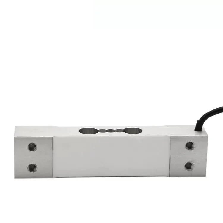
| Model | Body | The job it belongs to | Capacity | The number that decides it |
|---|---|---|---|---|
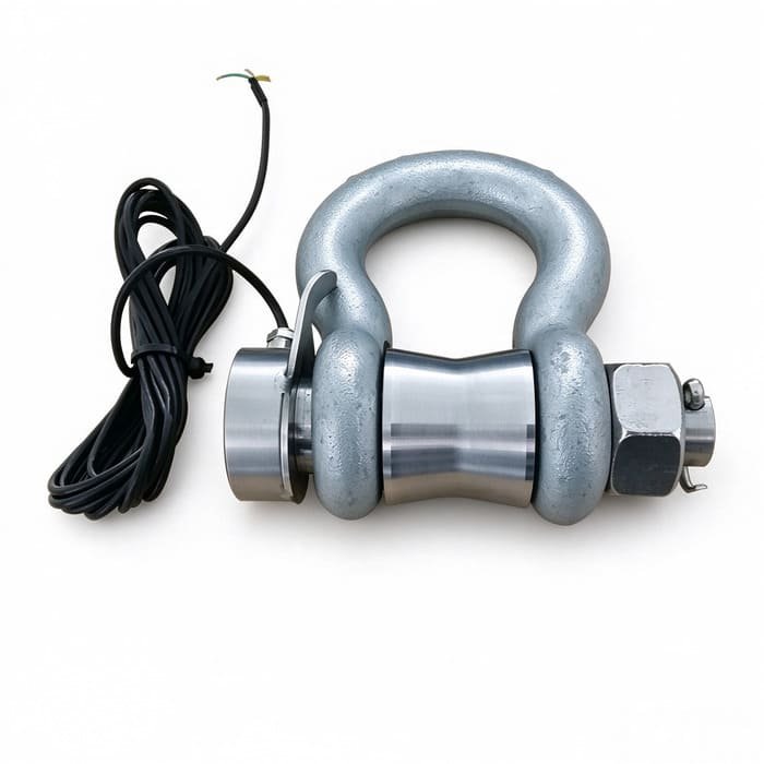
| WST709 | Stainless load pin in a bow shackle | The line: a mooring leg, a bridle, a hoist or a tow pennant | 1 to 100 t | The peak over a quarter, and the off-axis behaviour nobody publishes |
| WST403 | Plate ring tension element | Heavy in-line tension, winch and deck lines, the offshore end | 20 to 2000 kN | Creep and temperature, because the chain around it is the tightest of the three |
| WST201 | Single-point platform element | The deck: sample bin, mortality bin, feed sample tray | 3 to 100 kg | Impact on a lowered basket, against a 120 % safe overload |
Two parts sit beside the cells, and on a long cable run at sea they decide more than the cells do. A four-channel stainless junction box is what lets a pair of legs share one excitation and one converter, which is the difference between comparing two lines and comparing two instruments. And a stainless indicator with RS-485 output is where the peak-hold, the threshold counters and the log actually live; a 4–20 mA and Modbus RTU transmitter does the same job when the number has to travel 200 metres of barge to a PLC. If the requirement is a wireless shackle rather than a cabled one, there are wireless pins and full wireless shackle links in the WST905 pin shackle and WST904 shackle link families, and I would want to see the battery duty cycle and the radio path before recommending either on a barge.
| What I do supply | What I do not |
|---|---|
| Shackle cells, plate ring elements and single-point platform cells, with a factory calibration certificate | The mooring analysis, the site survey, the dynamic amplification factor, the fatigue assessment |
| Pins machined to fit shackle bodies you already own, and a load-centralising bobbin where the azimuth moves | The NS 9415 facility certificate, or a DNV product certificate for a mooring component |
| Matched bridge resistances across a set, junction boxes, transmitters and indicators with peak-hold and logging | The cage, collar, net, barge, winch or control system, and the rigging replacement decision |
| Cable length, connector and gland chosen for the route, and a stated depth and duration for any IP68 claim | A safety-rated overload trip or interlock, and the risk assessment that decides how the number is used |
| The sizing arithmetic, shown, and an honest list of which numbers on our own pages you should question | Any statement that your farm complies with NYTEK23, NS 9415, RAMA or anything else |
Five questions, and I can quote from the answers
- What is the highest tension this node can ever see, and what sequence of events would produce it? The second half of that question matters more than the first.
- How many legs are there, at what angles, and which one governs? A cell in the wrong leg produces a correct number about the wrong thing.
- Which direction does the line point at the fairlead, and does that direction move? If it moves, the answer is a bobbin or a swivel, or two cells.
- How long does one reading have to survive, and who looks at it? A quarter of unlogged data has the same value as no data, and a 1 Hz log is 31 MB.
- Where does the number go — a bridge display, a PLC, a cloud platform or an insurance file? That single answer decides the output format, the cable, and whether the peak ever gets recorded.
If you want the neighbouring subjects, read them in this order. Load cells for shrimp feeders is the feed-metering argument on the other side of the industry, where one 0.05 %F.S datasheet lands on nine capacities and the smallest dose inherits the largest range. Load cells for lifting platforms is the overload-protection side of rigging, which this article deliberately stays out of. The push-or-pull article on dynamometers and force plates is the same force-measurement problem without a mooring around it. The wireless dynamometer guide is where I first wrote down what an oversized safety factor on a shackle costs, and load cells for TMR feed mixer wagons is feed mass again, on land, where the machine never stops moving either.
Questions I Hear Every Week
What is a shackle type load cell, and is it the same as a load link?
A shackle type load cell is a strain-gauge instrument built into the pin of a bow shackle. The pin is replaced with a calibrated load pin that has a machined measuring section and a full Wheatstone bridge inside it, so an ordinary rigging component becomes a measurement point without adding any height to the assembly. A load link or dynamometer is a separate in-line body that goes between two shackles and does add length. A load pin is the same instrument without a shackle body around it. All three measure the same quantity and all three are available in this catalogue. The difference that decides it on a mooring node is whether you are replacing a part or adding one, because on a certified node that decides who signs what.
Do I need one cell or two on a bridle?
Two, and it is the cheapest redundancy in this article. A load cell cannot report that it has stopped working: a channel that fails short keeps returning its last value, and a constant reading is indistinguishable from calm weather. On the Chiloe grid that went on for eleven days before anyone noticed. With two cells on legs that ought to track you get a quantity that ought to be constant, and a rule you can write. You also get the asymmetry, which is the finding that saves money, because an uneven grid loads four legs to 74 % of the total while every single-leg check still passes. And you get the divisor: with one cell in a bridle you know the tension but not the angle, and the angle is worth up to 74 %.
How accurate does a mooring load cell need to be?
Less accurate than almost any buyer expects, which is why I keep writing this answer. On a 25 t shackle, a 0.5 %F.S accuracy figure is 125 kg. In the Hitra quarter the wave-frequency component of the load was 49 % of full scale, which on the same cell is 12 250 kg: 98 times the accuracy figure. So the accuracy line was never the limiting term, and paying for 0.25 %F.S buys you a number that is still two orders of magnitude smaller than the thing that broke the line. Buy 0.5 %, spend the difference on ingress rating, a sensible cable route, a load-centralising bobbin and a second cell. Then demand the two figures no load shackle datasheet publishes: creep over the period you intend to leave it installed, and zero drift per 10 °C. Get both written into the order, because a slow zero walk over two years is the one error nobody can filter out of a permanent installation.
Can a load cell weigh a cage, or the biomass in it?
No, and I have refused that request. A cell in a leg reports the axial tension in that leg. The cage’s mass is divided among however many legs the grid has, each leg’s share depends on the angle that leg makes with the vertical, the fish are close to the density of the water they swim in so they contribute almost nothing to the lines holding the enclosure on station, and what dominates the reading is the drag of the water moving through a fouled net. Anyone quoting you a load cell to weigh a cage has not done the arithmetic. Weigh forty fish in a bin on a deck platform and multiply, which is the third job in chapter 1 and costs a fraction of instrumenting a grid. There is one exception worth knowing: put the cell in the hoist line that lifts the bottom weight system and you can weigh what is fouling the net, because that 4.8-tonne chain and tube comes out of the water with the net attached to it.
How should I record the data?
At 1 Hz, with peak-hold switched on, and with two counters attached: minutes spent above a threshold, and cycles above a threshold. Ninety-one days at 1 Hz is 7.86 million samples and 31.4 MB as four-byte values, which no logger built this decade has an excuse for not storing. Add 10 Hz if you want the vessel-call transients, which never appear in a wave analysis. Never a ten-minute average: a 600-second window contains 75 cycles of an 8-second sea, and 49 % of full scale of dynamic content arrives as about 0.65 %. The correct answer costs 31 megabytes; the wrong answer cost one site nine weeks of blindness and a failed bridle.
Will your shackle cell work subsea?
IP67 is splash and temporary immersion. IP68 is a promise that means nothing without a depth and a duration attached to it, so ask for both numbers in writing before you submerge anything. Our own page offers IP68 for continuous subsea duty and does not state either number, so that is a question I would rather you put to me than assume. Two more things from the same conversation. The pin is rarely the failure point; the cable entry and the connector are, which is why a subsea-rated connector and a strain-relieved gland are worth more than an extra decimal of accuracy. And a pressure test is a laboratory statement about a static head, not a statement about a shackle being worked back and forth in a tidal flow for two years.
Do you supply the mooring analysis, the certificate, or the alarm that trips the winch?
No to all three, and I would rather write it here than bury it in a quotation. I export the sensing layer: load cells, junction boxes, transmitters and indicators, with a factory calibration certificate and the sizing arithmetic that goes with them. The mooring analysis, the site survey, the dynamic amplification factor, the fatigue assessment and the facility certificate belong to an engineering house and an accredited inspection body. On a Norwegian site the mooring shackle is itself a product-certified component, so if the node needs a certified shackle, keep it there and put the instrument somewhere else in the same load path. And an overload trip is a safety function, which is a different object from a measuring instrument that closes a contact. I will not sign the risk assessment that decides how a farm uses the number.
What do you need from me to quote?
A sketch of one leg, drawn by hand, with the angle it makes and the number of legs on the anchor. The highest tension that node can ever see and the sequence of events that would produce it. Whether the line’s direction at the fairlead is fixed or swings. How long one reading has to survive and where the number goes. And the pinch point the cable has to get past. Six lines of information and I can size a shackle type load cell for aquaculture equipment, show you the arithmetic and quote in one reply, usually within 12 hours on a working day. The sketch matters more than the specification sheet: I have sized more mooring projects from a photograph of a shackle with a ruler laid across it than from any table of requirements, and I would rather argue about the angle before somebody machines a pin.
One hand sketch of one leg, the angle it makes, how many legs share the anchor, and whether the line’s direction moves. Those four lines are enough for me to send back a sizing note with the arithmetic shown. If the shackle type load cells for aquaculture equipment you have in mind are the wrong range, the wrong ingress rating, or sitting on a node that a certified component has to hold, I would rather tell you before the pin is machined.
Get an Aquaculture Load Cell Quotation
More field notes: the blog index · complete guide · selection guide