
Truck Scales · Weighbridges · Eight Cells, One Sum
The display averages the eight signals and adds the eight zero errors.
Nobody who asks me for a load cell for truck scale work wants to hear that the cell is not the problem. I have quoted these bridges for eleven years, and the failures I get called about are almost never a cell that died. They are a sum that nobody added up: eight cells wired in parallel, one display, and a set of arithmetic rules that are completely different from the ones that work on a bench scale.
This article is the arithmetic I run before I quote a weighbridge — the capacity formula, the microvolt-per-division gate, and the one calculation that decides whether a 10 kg division is available to you at all.
What this covers
- What a truck scale is, and what a truck does to it
- The display adds your cells
- Where 30 tonnes comes from
- Microvolts per division: the gate nobody computes
- The junction box is where a bridge is won or lost
- The legal chapter: what the tender gets wrong
- Eleven questions, and the four cells I quote
- Frequently asked questions
What a truck scale is, and what a truck does to it
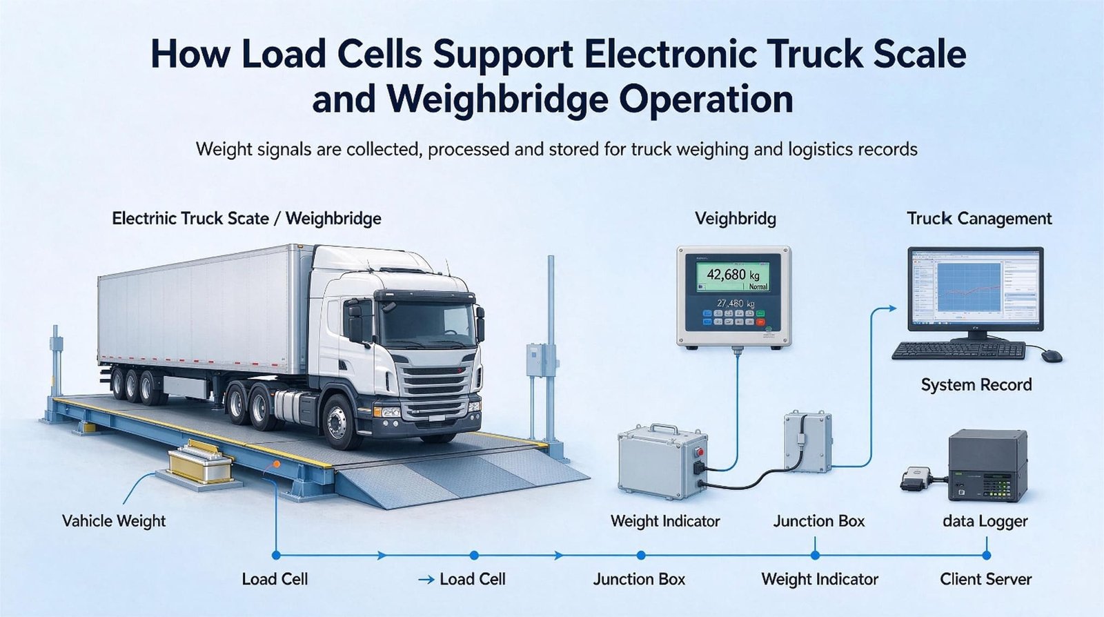
A road weighbridge is a steel or steel-and-concrete platform, three metres wide and between six and twenty-four metres long, carried on four, six, eight, ten or twelve compression load cells, wired through one junction box into one indicator. The indicator does not read eight cells. It reads one voltage, and that voltage is the average of eight, which the instrument then multiplies by a constant so that the display shows tonnes.
That sentence is the whole article compressed. Everything below is what happens when you take it literally.
The vocabulary matters more than usual here, because two different things get called a weighbridge. In the colloquial sense a weighbridge is the road vehicle scale in a yard; in the metrology sense, and specifically in the European Measuring Instruments Directive, a weighbridge is a rail weighbridge. I will come back to that in the legal chapter, because it is the single most expensive confusion I see in tender documents.
| Platform | Capacity (Max) | Cells |
|---|---|---|
| 4 m × 2 m | 8–15 t | 4 |
| 6 m × 3 m | 15–30 t | 4 |
| 7.5 m × 3 m | 20–40 t | 4 |
| 9 m × 3 m | 30–50 t | 4 or 6 |
| 12 m × 3 m | 40–80 t | 6 or 8 |
| 15 m × 3 m | 50–60 t | 6 or 8 |
| 18 m × 3 m | 80–120 t | 8 or 10 |
| 24 m × 3 m | 80–120 t | 10 or 12 |
That table is not my invention. It is the platform-size table a national measurement authority publishes as the basis for approving weighbridge installations, and it is worth reading twice because it carries two things every designer should copy. First, capacity and cell count move together, not independently. Second, a 3 m × 18 m platform is listed at 80–120 t with the same eight or ten cells — the platform length buys you the vehicle, and the cells buy you the load.
Alongside the cell count, five decisions get made before a cell is ever chosen, and they are made by the bridge builder, not by me.
| Decision | The two options | What it changes for the cells |
|---|---|---|
| Installation | Above ground, or in a pit | A pit is the lowest point on the site; the cells and the box live in it |
| Deck | All steel, or steel filled with concrete | The dead weight more than doubles — and it is charged to the same capacity |
| Signal | Analogue mV/V, or digital RS-485 | Digital removes the parallel-resistance problem; it does not remove the zero problem |
| Duty | Static (the driver stops), or dynamic (in motion) | In-motion weighing is a different class of instrument with a different standard |
| Type | Single deck, or multi-deck / rail | Changes the cell count, not the cell arithmetic |
The one question that decides everything downstream
A weighbridge is on the “yes” side of the only test this series uses: is a price computed from this reading? Yes — a weighbridge ticket is a commercial document, so the whole instrument is legally controlled, and the type approval, the marking and the periodic verification belong to the bridge builder and the owner. What I sell is the load cell, the junction box, the indicator and the matching data. I do not sell the approval, and I will not write the sentence that says I do.
Now the truck. A road vehicle is not a spread load, and this is where weighbridge arithmetic parts company with every other weighing application I write about.
Under EU Directive 96/53/EC a single non-driving axle may weigh 10 t and a single driving axle 11.5 t. A trailer tri-axle group may weigh up to 24 t. In China, GB 1589-2016 sets the same 10 t and 11.5 t per axle, with 49 t for a six-axle combination. Those are legal ceilings on a group of two or three axles that sit within about 1.4 m of each other.
On an 18 m bridge with eight cells — four longitudinal positions, two cells each — the module positions are roughly 4.5 to 5 m apart. A 24 t tri-axle group therefore lands on one pair of cells, not on all eight. That is 12 t per cell. On a 3 m × 6 m platform with four cells it is worse: the group lands on one cell, or between two, and the deck does all the distributing.
So the first arithmetic rule of a truck scale is not about the total weight at all. It is this: the cell is sized for the worst group of axles, and the platform is sized for the longest vehicle. Everything that follows is a correction to that one idea.
Arequipa, March 2026: the deck was the first customer
A bridge builder in Arequipa, Peru sent me a bill of materials in March 2026 for a 3 m × 18 m platform at 80 t. Four cells of 20 t each. His reasoning was written in the email: eight cells would be more money, and 80 divided by four is 20.
I did not quote it, and I did not lecture him either. I sent back the arithmetic in the next section and asked two questions instead: is the deck steel or steel-and-concrete, and what is the site altitude? The answer was concrete, and 2 335 m.
The concrete deck is the finding. A manufacturer who publishes both versions of the same 18 m × 3 m platform lists 7 742 kg without concrete and 20 500 kg with it. Same bridge, same capacity, 2.6 times the dead weight. His four 20 t cells were being asked to carry a platform that had already spent a quarter of the capacity before the first truck arrived — and his deck needed eight cells anyway, because an 18 m platform on four supports sags in the middle. He ordered eight cells of 40 t. The bridge has been running since June.
The display adds your cells
Here is the derivation that changed how I quote weighbridges, and it is four lines long.
Every cell produces a voltage proportional to the load on that cell, divided by its own capacity. Wired in parallel, with matched output impedances, the group presents the average of those voltages. The indicator is then calibrated so that the full load produces the full-scale voltage. Put that together and the reading is:
reading = W + Σ zj
where W is the true weight and zj is the zero error of cell j, expressed in kilograms at that cell. Not divided by eight. The zero errors add up.
The reason is easy to see once you accept it. The instrument’s scale factor is eight times finer than a single cell’s, because it believes each cell only carries an eighth of the load. So an offset that means half a kilogram to a cell becomes four kilograms on the display. Eight cells, eight offsets, all added.
Now put a real number on it. A 30 t canister cell with a temperature effect on zero of 0.0018 % of full scale per degree Celsius drifts, at cell level, by 0.54 kg per degree. On its own that is unremarkable — it is 0.000018 of a 30 t capacity, and every cell in this class is specified the same way. Eight of them together, with the instrument reading eight times finer, is a different animal. This is why the load cells for truck scales I recommend are the ones whose zero effect is published per degree rather than per 10 K — per-degree is the only version of that number you can compare across models without a calculator.
| Cell | Zero drift per °C | Per cell | Cells × capacity | On the display, per 5 K | In divisions, e = 20 kg |
|---|---|---|---|---|---|
| WST511 | 0.0018 %/°C | 0.54 kg | 8 × 30 t = 240 t | 21.6 kg | 1.08 e |
| WST511 | 0.0018 %/°C | 0.54 kg | 6 × 30 t = 180 t | 16.2 kg | 0.81 e |
| WST506 | 0.0020 %/°C | 0.60 kg | 8 × 30 t = 240 t | 24.0 kg | 1.20 e |
| WST511 | 0.0018 %/°C | 0.72 kg | 8 × 40 t = 320 t | 28.8 kg | 1.44 e |
| WST507 | 0.0050 %/°C | 0.50 kg | 4 × 10 t = 40 t | 10.0 kg | 1.00 e |
| WST502 | 0.0050 %/°C | 5.00 kg | 8 × 100 t = 800 t | 200 kg | 4.00 e |
The first row is an 80 t bridge on eight 30 t cells, and it produces 1.08 divisions of zero movement for every 5 K of temperature change. The legal limit for the whole instrument — not for a component, for the finished scale — is one division per 5 K. A component that is going to be verified separately is normally allowed 0.5 to 0.7 of the instrument’s temperature error, which puts the cell group’s own allowance at 0.5 to 0.7 e. Against that, 1.08 e is between 1.5 and 2.2 times over.
I want to be precise about what that does and does not mean. It does not mean the bridge will fail verification, because a real installation has an automatic zero-tracking device in operation during the test, and the test protocol asks the examiner to record whether it is in operation precisely because it matters. What it means is that the zero-tracking device stops being a convenience and becomes part of the metrology. And it can only track while the bridge is empty, within its permitted band.
There is a published method for turning that drift rate into an interval, which I use in every conversation about outdoor bridges. It comes from the zero-error chapter of a European cooperation guide for approved instruments: if the zero drifts 0.25 e per 5 K and the ambient changes 5 K per hour, then a 0.5 e zero allowance is exhausted after two hours, and the instrument has to be re-zeroed at least that often. Apply the same arithmetic to the first row of my table and 1.08 e per 5 K at 5 K per hour exhausts 0.5 e in 28 minutes.
I am not saying a weighbridge in a desert must be re-zeroed every half hour. I am saying that the number is knowable before you buy, and that in eleven years I have never once had a customer ask me for it. The two answers that come out of it are engineering answers, not purchasing answers: put the bridge in a pit rather than on the surface, so the deck is not a solar collector, and do not let anyone persuade you into a finer division without redoing this table.
The sentence I keep repeating
You are not buying eight load cells. You are buying one addition. Every cell’s zero is a term in that sum, and the finer your division, the more expensive each term becomes — because the drift is fixed in kilograms while the division you are measuring it with keeps getting smaller.
The other half of the sum: span errors follow the load
Zero errors add. Span errors behave completely differently, and the difference is where most weighbridge arguments with customers actually live.
If cell j has a span error of δj, the error it contributes to the display is δj times the load on that cell. So a spread load divides the error across the cells that carry it, while a concentrated load does not. A truck is the most concentrated load a legal-for-trade instrument ever sees.
| Where the 80 t sits | Load on the affected cell | Error from one cell 0.10 % off | In divisions |
|---|---|---|---|
| Spread evenly over 8 cells | 10 t | 10 kg | 0.5 e |
| Four cells | 20 t | 20 kg | 1.0 e |
| One module pair (two cells) | 40 t | 40 kg | 2.0 e |
| One cell | 80 t | 80 kg | 4.0 e |
Read the top row and the bottom row together, because they explain a failure mode that costs people enormous amounts of time. A calibration test spreads the load; a truck never does. If the corner trim in the junction box was set with a spread reference load, an individual cell’s span error is divided by eight and disappears into the noise. Park a truck on one side of the deck and the same error appears at full strength.
That is why the standard test for a vehicle scale is not a stack of weights on a corner. The pattern-evaluation procedure for non-automatic weighing instruments lists the eccentricity test for these instruments in two forms, and the second one is eccentricity using a rolling load — a vehicle that is driven across the platform. The drafting committee knew what the calibration weight does not do.
Jeddah, July 2026: the same truck weighing 60 kg differently
A quarry operator in Jeddah wrote to me in July 2026 with a complaint that had almost no technical content: the same truck, the same load, two different weights depending on where it stopped, up to 60 kg apart. Worse in the afternoon than in the morning. Two other bridge builders had already told him the load cells had “drifted” and quoted him a replacement set.
I asked for three things and no order: a day of tickets with the stop positions, a photograph of the pit at 3 pm, and the model of the indicator so I could read its zero-tracking settings. The tickets showed the pattern immediately. Weight rose by around 60 kg when the trailer was at the north end and fell back when it was at the south end. That is not a cell that has changed; that is a gradient, and the arithmetic above tells you where to look.
60 kg on a module carrying 12 t is a 0.50 % span difference between two module positions. The likely candidate was the corner trim, set in the morning with a spread load — the exact error the table above predicts. What made it worse in the afternoon was thermal: an 18 m steel deck in full sun develops a temperature difference along its length, so the four cells at one end are warmer than the four at the other. Ten Kelvin across a side of four cells is 21.6 kg of zero offset on that side — 1.08 e, and opposite in sign to the other side. Add the two effects and 60 kg is not mysterious at all.
The fix cost him nothing in cells. He re-trimmed the corners with a rolling load, axle group by axle group, sitting on each module position in turn, until the spread across positions was under 20 kg. He finished the pit walls so the deck sits lower and out of the wind that was sweeping under the north end and cooling it. And he stopped telling his drivers they could stop anywhere — the last part was free and did more than the other two.
The measurement that decided it was one afternoon of tickets. I have never once diagnosed a weighbridge complaint from a specification sheet, and I have been asked to try several hundred times.
Where 30 tonnes comes from
Ask a weighbridge builder why he specified 30 t cells on an 80 t bridge and you will usually get one of two answers: “that is what we always use”, or “because 40 t is more expensive”. Both are true and neither is a reason. Here is the actual reason, and it comes out of the same capacity formula that professional weighing-system literature has used for decades.
C = K0 · K1 · K2 · K3 · (Wmax + W) / N
C is the rated capacity of one cell, Wmax is the maximum capacity of the scale, W is the weight of the platform, and N is the number of cells. K0 is a safety factor, normally 1.2 to 1.3. K1 is the dynamic factor for impact, quoted in the source as 1.0 to 1.5. K2 is a centre-of-gravity offset factor, 1.0 to 1.05, and K3 a wind factor, 1.0 to 1.05.
Take the mainstream platform: 3 m × 18 m, 80 t, eight cells, and the 9.0 t steel deck one Chinese manufacturer publishes for exactly that size. K0, K2 and K3 at their nominal values multiply to 1.378, and (80 + 9) / 8 is 11.125, so C = 15.33 × K1 tonnes. Now walk K1 up.
| K1 | What it assumes | C, steel deck (9 t) | C, concrete deck (20.5 t) |
|---|---|---|---|
| 1.0 | The truck is set down, not driven on | 15.3 t | 17.3 t |
| 1.3 | The “1.5 × maximum axle” rule | 19.9 t | 22.5 t |
| 1.5 | Top of the range quoted in the source | 23.0 t | 26.0 t |
| 1.8 | Ramps are slightly proud of the deck | 27.6 t | 31.2 t |
| 2.0 | A loaded truck rolling on in low gear | 30.7 t | 34.6 t |
There it is. At K1 = 2.0 the steel deck asks for 30.7 t and the concrete deck asks for 34.6 t. The available capacities run 20, 30, 40, 50 t. Both bridges round up, and they round up differently. Whether your deck is steel or steel-and-concrete decides which cell you have to buy.
The mechanism is worth stating plainly, because it is the part people find surprising. That 11.5 t of extra concrete is divided by eight cells and then multiplied by the same four K factors, so it costs 3.96 t on every cell. Eleven and a half tonnes of concrete, inserted once, is paid for eight times. It also puts you in the batching business, which is a different instrument entirely: if your site also runs a mixer or a hopper, the same dead weight has to be handled by other engineering, and I wrote about that separately in load cells for concrete batching plants.
And look at what happens if you reverse the question. If you buy 20 t cells, you are implicitly declaring K1 = 1.30. If you buy 30 t cells, you are declaring K1 = 1.96. Neither is wrong; they describe two different bridges and two different ramps. What is wrong is buying 10 t cells, because that requires K1 = 0.65 — a dynamic factor below one, which is the mathematical way of saying that a truck has to be lifted onto your platform rather than driven onto it.
The “1.5 × the axle” rule, checked against the same formula
You will find this rule everywhere: size each cell at 1.25 to 1.5 times the maximum axle load. On our bridge the worst legal axle group is a 24 t trailer tri-axle, so 12 t per cell, and 1.5 × 12 t is 18 t — a 20 t cell. The rule and the K-formula disagree by a factor of 1.7, and the reason is that the rule only knows about the axle. It does not know about the 9 t (or 20.5 t) platform, the centre-of-gravity offset, the wind, or the fact that on an eight-cell bridge the load is never shared as evenly as a formula assumes. Use the rule as a sanity check. Do not use it as the calculation.
One more check, because this is the number customers arrive with. Eight 30 t cells on an 80 t bridge is 240 t of installed capacity, or three times the maximum capacity. Six cells gives 2.25 times; four cells gives 1.5 times. Those ratios are not arbitrary either — they are what the K factors produce when you feed them a real platform. When someone tells you a bridge “has three times the capacity” as if it were generosity, what they have actually told you is that the platform weighs about 9 t and the truck rolls on.
Which raises the question I get asked most often after a quote is refused: then why is a 30 t cell not simply stronger?
Because it does not need to be. A 30 t cell with a 150 % safe overload has 45 t of safe load, and the worst legal axle group puts 12 t on it — 26.7 % of that margin. Even a 20 t cell would only be at 40 % of safe load. The oversizing is not buying strength; a 10 t cell would survive the axles too. What it is buying is stiffness, a smaller zero drift as a fraction of the reading, and enough headroom that the dead weight of the platform does not eat the working range. The capacity you buy on a weighbridge is a stiffness and stability budget, not a strength budget.
Microvolts per division: the gate nobody computes
The email I get most often about a weighbridge is one sentence long: we want 10 kg divisions on an 80 t bridge. In eleven years I have never received that sentence together with a second one containing the microvolt-per-division calculation. That calculation takes four numbers and decides whether the 10 kg division exists at all, and it is now where every load cells for truck scales enquiry I receive begins — before a price is discussed and long before a purchase order exists.
Here is what it describes. One division of the display is a small weight, and a small weight produces a small voltage. The indicator has an input sensitivity floor — below roughly 1 microvolt per division, its own resolution and noise take over. If your bridge asks for a division that generates less signal than that, the last digit will flicker, and a flickering division is worse than a coarse one, because it is legally unusable and it destroys the operator’s trust in the scale.
µV/d = 1000 · S · Uexc · d ÷ (N · C)
S in mV/V | Uexc in V | d, C in kg | N = number of cells in parallel
A worked example was written by a colleague in a Chinese weighbridge system-design manual in 2016, and I keep the page because it is the small version of our problem: a 3 t platform, 3 000 divisions, four cells of 1.5 t, 2.0 mV/V sensitivity, 5 V excitation. That is 1.67 microvolts per division against a limit of 1. An ordinary bench case, with ordinary margin.
Now run the same arithmetic on the trucks. I used 10 V excitation and 2.0 mV/V cells, which is what most weighbridge indicators supply and what all four of the cells I recommend deliver.
| Bridge | Division e | Cells × cap. | Sens. / exc. | µV/d | Verdict |
|---|---|---|---|---|---|
| 60 t | 20 kg | 8 × 30 t | 2.0 / 10 V | 1.667 | passes, with nothing to spare |
| 80 t | 20 kg | 8 × 30 t | 2.0 / 10 V | 1.667 | passes |
| 80 t | 10 kg | 8 × 30 t | 2.0 / 10 V | 0.833 | fails — halving e halves the signal |
| 80 t | 20 kg | 8 × 30 t | 2.0 / 5 V | 0.833 | fails — a 5 V indicator costs you the division |
| 80 t | 20 kg | 8 × 30 t | 1.0 / 10 V | 0.833 | fails — and 1.0 mV/V cells are sold as weighbridge cells |
| 80 t | 20 kg | 6 × 30 t | 2.0 / 10 V | 2.222 | passes comfortably — fewer cells, more signal each |
| 80 t | 20 kg | 10 × 30 t | 2.0 / 10 V | 1.333 | passes |
| 80 t | 20 kg | 8 × 40 t | 2.0 / 10 V | 1.250 | passes |
| 80 t | 50 kg | 8 × 30 t | 2.0 / 10 V | 4.167 | a lot of room |
| 100 t | 20 kg | 10 × 50 t | 2.0 / 10 V | 0.800 | fails |
| 100 t | 50 kg | 10 × 50 t | 2.85 / 10 V | 2.850 | passes — this is what 2.85 mV/V buys |
Read the third, fourth and fifth data rows together, because they are the same 80 t bridge three times. Asking for 10 kg divisions, supplying 5 V instead of 10, or buying cells at 1.0 mV/V instead of 2.0 all cut the signal exactly in half. Three different purchasing decisions, one identical outcome, and none of the three appears anywhere on a quotation. Note also what the first of them does to the chapter before this one: the same eight 30 t cells that drift 1.08 e per 5 K at 20 kg divisions drift 2.16 e per 5 K at 10 kg, because the drift is a fixed number of kilograms and you have just halved the kilogram the division represents. A finer division never costs you only the resolution you asked for.
The single most useful sentence in this article
A division is a promise the display makes and the cell does not co-sign. Before you promise 10 kg on an 80 t deck, put the four numbers through the formula. It takes ninety seconds, and it is the difference between a bridge that reads and a bridge that flickers.
n, Min, and the two gates on the cell side
The microvolt gate is on the indicator. There are two more, on the cell, and they are the ones that decide whether the cell class you were quoted is actually adequate.
The first is the count itself. A class C3 cell is defined as being good for 3 000 verification intervals, and the number of intervals on your bridge is n = Max / e. Sixty tonnes at 20 kg is exactly 3 000 — the classic municipal weighbridge sits precisely on the C3 line, which is why so many of them are specified C3. For the divisions people ask about most on an 80 t bridge it is 4 000 at 20 kg, 8 000 at 10 kg, and 1 600 at 50 kg. But n is the instrument’s count. The cell only carries its share, so the figure that has to fit under the cell’s 3 000 is:
nLC = (Max + T) ÷ (e · N)
T = maximum tare allowance
On an 80 t bridge with 20 kg divisions and eight cells, allowing 20 % for tare, that is (80 000 + 16 000) ÷ (20 × 8) = 600 intervals per cell. A C3 cell has 3 000. This is the opposite of what most buyers assume: the per-cell demand is lower than the bridge’s, by a factor of N. So a 4 000-division bridge does not require C4 cells, and anyone who tells you it does has not done the division.
The second gate is the finer one, and it is where the cell class finally bites. In a multiple-cell instrument the compatibility rule used during type evaluation is that the instrument’s division must be at least the square root of N times the cell’s own minimum verification interval:
vmin ≤ e ÷ √N
For class C3, the published R60 classification puts the ratio of capacity to minimum verification interval at 12 000 to 1. Work out what that means per cell on eight cells:
| Cell (C3, Y = 12 000) | vmin | Finest e allowed on 8 cells | Is 10 kg available? |
|---|---|---|---|
| 20 t | 1.67 kg | 4.71 kg | yes, with room |
| 30 t | 2.50 kg | 7.07 kg | yes |
| 40 t | 3.33 kg | 9.43 kg | yes, but by 6 % |
| 50 t | 4.17 kg | 11.79 kg | no |
On eight 30 t class C3 cells, the finest division the cells will support is 7.07 kg. Ten kilograms is inside that. So when a customer asks for 10 kg on an 80 t bridge, the answer is not “buy a higher class” — the class is fine. The answer is that the indicator will not resolve it at 5 V, or with 1.0 mV/V cells, or if you stack 10 cells on the deck. That distinction is worth real money, because upgrading a cell class costs more than changing an indicator setting.
And there is a floor as well as a ceiling. The minimum capacity is 20 e, so an 80 t bridge at 20 kg divisions is legally meaningful from 400 kg upward. That matters more than it sounds: if your site also wants to weigh pallets or a single IBC on the deck, and 400 kg is above what they weigh, the bridge cannot do that job regardless of how good the cells are. Two different tasks, two different instruments.
Finally, the error budget the readings are judged against, for class III with e = 20 kg: plus or minus 0.5 e up to 500 e, plus or minus 1.0 e from 500 to 2 000 e, and plus or minus 1.5 e above that. In kilograms on an 80 t deck that is ±10 kg up to 10 t, ±20 kg up to 40 t, and ±30 kg at full load. I keep those three numbers in mind because they are the only thing a customer actually cares about, and they are also the yardstick for every error I calculated in the previous chapter. The 12 kg of span error from a 0.10 % mis-trim on 12 t is 0.6 e — not a problem. The 30 kg from a 0.25 % one is 1.5 e — already the full allowance at high load, before the cells contribute anything at all.
The impedance bill, and why the cells are 1 000 ohms
An indicator datasheet hardly ever says “up to eight cells”. It says something like “4 × 350 Ω or 8 × 700 Ω”, and those two phrases are the same number: 87.5 Ω. Cells in parallel divide their impedance by N, so the only thing the indicator is really rated for is a minimum group resistance.
| Cell | Input / output | Group, 8 cells | Against a 87.5 Ω rating |
|---|---|---|---|
| WST511 | 1100 / 1000 Ω | 137.5 / 125 Ω | easy |
| WST506 | 450 / 480 Ω | 56.25 / 60 Ω | needs a capable indicator |
| WST507 | 380 / 350 Ω | 47.5 / 43.75 Ω | twice as hard — check the indicator |
| WST502, high-Z | 4450 / 4010 Ω | 556.25 / 501.25 Ω | easiest of the four |
Eight 350 Ω cells give 43.75 Ω, exactly half of the 87.5 Ω an indicator rated “4 × 350 or 8 × 700” is built for. That is the whole reason a bridge cell is wound at 1 000 Ω rather than the 350 Ω that every bench cell uses: not accuracy, not cost, just the ability to put eight of them in parallel without exceeding the excitation current the indicator can supply. If you are designing a ten-cell 120 t deck, this table is the one to check before you check anything else.
Altitude: the question nobody asks
I ask it on every quote now, because of the Arequipa project. A cell that is not hermetic breathes, and the pressure inside the case follows the weather and the altitude. The R60 zero-error allowance for a change in static pressure is 1 e per kilopascal. Sea level is about 101.3 kPa; at 2 335 m, where that bridge stands, the ambient pressure is about 76.0 kPa.
A cell calibrated at sea level and installed at 2 335 m therefore faces a 25.3 kPa step. At the legal limit of 1 e per kPa that is 25 e — and at e = 20 kg, 506 kg of offset. In practice a vented cell never lands anywhere near its own limit, because the manufacturer’s internal compensation absorbs most of it. But you cannot know which side of the limit you are on unless you ask, and there is an easy way to close the path entirely: specify a fully welded, hermetically sealed cell (IP68 or IP69K). WST511 is welded, 304 stainless, laser-sealed. A 506 kg question disappears for the price of a welding pass and a gland.
The junction box is where a bridge is won or lost
Everything in the previous chapter came from one fact: the display adds your cells. The junction box is where that addition physically happens, and therefore it is the only place on a weighbridge where you can reach in and subtract a cell’s error. That makes it the most underrated component in the bill of materials, and in my experience it is also the most likely to be the actual fault.
Electrically, the box is unglamorous: the eight excitation pairs join, the eight signal pairs join, the screen drains, and a small board carries two trim potentiometers per cell. Those potentiometers slightly load the signal of one cell, which changes its effective sensitivity, which is how corner adjustment works. Turn one, and you have made that corner “heavier” or “lighter” without touching a cell. If you want the terminal-by-terminal version of that board — the wiring colours, the trimming order and how to tell which pot is doing what — I wrote it up as a step-by-step guide to load cell junction box wiring and adjustment, and it is the page I open on site myself.
That is the good news. The bad news is that the box is a single physical object sitting inside the same temperature field as the deck, and every trim on that board is a term in the zero sum. A temperature gradient across the board — sun on one end of the lid, a shadow on the other — bends the reading by however much the trims drift, and because those trims sit in series with signals that the indicator reads eight times finer, a small board error becomes a visible kilogram error. It also explains a phenomenon my customers report constantly and misdiagnose: a bridge that weighs the same truck differently in the morning and the afternoon, and goes back to normal after a re-zero, is almost never a cell. It is drift.
Three rules I now put in every weighbridge quotation
1. Mount the box where it is not the low point. Water finds the box, not the cells. Put it on the wall of the pit, above the cable entries, never on the deck bottom where it collects splash and condensation.
2. Specify IP68 with real glands, then check that the sealing concept matches the climate. A potted box is genuinely sealed; a box with a breather is not, and a monsoon site will prove it within one season.
3. Use six-wire cable if the run is long. On a 24 m deck the excitation leads are tens of metres of copper, and their resistance changes with temperature. Sensing at the cell instead of at the indicator removes that term from the sum.
Kerala, monsoon 2026: eight good cells and one bad box
The call came from a site in Kerala, India, in the middle of the southwest monsoon in 2026. The complaint was that a bridge which had been fine all dry season now read a lorry 40 to 50 kg heavier at the north end than at the south end, and that the difference grew through a wet afternoon and then partly recovered overnight. The operator’s conclusion, stated with complete confidence, was that two of the cells had gone.
Before anything else I asked for two things: the corner readings with a known load, and a photograph of the junction box with the lid off. The photograph cost nothing and answered the question. The box had a quarter-inch of standing water in it, the trims were sitting in condensate, and the cable entries pointed upward. The lid gasket was there, but the drain hole in the bottom plate had been punched at the factory and never sealed or deliberately left — nobody could tell me which, and that ambiguity is itself the finding. Telling a dead cell from a drifting one is a ten-minute exercise if you follow a fixed sequence, and the sequence I use is the one I published as how to determine whether the load cell is damaged.
Put a number on what a wet box costs. Water across those trims shifts the effective sensitivity of one corner, and a 0.40 % span error on a module carrying 12 t is 48 kg — 2.4 e, more than the entire span allowance at that load. On the full 80 t it is 320 kg. And the size of the error is not the important part. The important part is that it moves with the water level, which is why it got worse through a wet afternoon.
So the answer I sent was that all eight cells were probably fine and they should not buy anything from me yet. Re-mount the box on the pit wall above the entries, replace the gasket, seal the unused cable entries with blanking glands, and re-run corner adjustment afterwards. They did it in a day, and the north-south difference collapsed to under 20 kg, which is inside the allowance. The site has since added a small hood over the box.
I want to be precise about what that episode did to my sales, because it is the reason I keep telling it. It sold one junction box, which is the cheapest item in the quotation. It could have sold eight cells. Every year a handful of sites replace eight perfectly good cells because a box they never look at was positioned badly, and the reason the misdiagnosis survives is that a wet box behaves like a temperature error and a temperature error behaves like a failing cell.
The general form of this advice works on every deck I have ever seen: before you buy any load cells for truck scale work, rule out the box, the cable, and the indicator. Cells are the most expensive part and the least likely to be the fault. I make my living selling them, and I would rather sell you one box than sell you eight cells you did not need.
The legal chapter: what the tender gets wrong
A tender document reached me last year with one line underlined by the buyer: load cells must be OIML R60 approved. In his reading, that sentence transferred responsibility for the bridge’s legality to whoever supplied the cells. It does not, and I now hold this part of the conversation before the quotation rather than after, because getting it wrong costs somebody a re-verification.
I test every weighing question with the same sentence: is a price computed from this reading? On a truck scale the answer is not in doubt. The ticket is a trade document and the reading is the quantity being paid for. That answer does two things at once. It makes the deck a legally controlled instrument, and it places the legal obligations on the instrument — not on the parts it is built from.
Type approval is an act performed on the instrument
In the European Union it is the instrument that is approved. MID 2014/32/EU does contain a weighbridge entry, MI-006, and it even names rail weighbridges explicitly — but MI-006 is drafted for automatic weighing instruments, and a road weighbridge at which the driver stops and waits is a non-automatic weighing instrument. It therefore lives under the NAWI Directive 2014/31/EU, with EN 45501 as the standard that gives presumption of conformity. OIML R76 is the international recommendation from which those requirements are drawn; it is a technical reference, not the regulation.
The consequence is administrative, and it is the reason I am careful about the word “approved”. The type approval is granted to a platform model, it is held by the platform manufacturer, and the first verification and every periodic verification after it are performed on the installed bridge for the benefit of the owner. Nobody sends a pallet of load cells to a metrology institute and receives a certificate that makes a deck legal.
What an R60 certificate covers, and what it does not
| A component certificate does cover | It does not cover |
|---|---|
| Combined error, creep, temperature effect on zero and on output, minimum dead-load output return, moisture resistance | The platform’s stiffness, levelness, foundation and ramps |
| The cell as a sub-assembly, tested on its own in a laboratory | The junction box, the cable, the indicator, or the way the eight are wired together |
| A capacity, a class, a number of verification intervals and a compensated temperature range | The accuracy of the assembled, installed and calibrated instrument |
| Evidence the platform manufacturer uses inside the instrument’s own type examination | Any statement that a bridge built around it is approved |
The distinction that protects both of us
A component certificate is evidence, not a permission. I will give you the cell certificate, the class, the capacity arithmetic and the microvolt figure, and I will defend every one of them in writing. What I will not do is sign a sentence saying the bridge is approved, because that act belongs to the platform manufacturer and the national metrology authority. Any supplier who offers you that sentence for free either does not understand the instrument or is writing you a dispute.
In China the deck is a mandatory-verification instrument
Most of the bridges my cells end up in are in China, the Gulf, South Asia and Africa, so the Chinese regime is worth knowing even if you never install there. A truck scale is a compulsory-verification measuring instrument. The verification of digital indicating scales follows the regulation JJG 539-2016, and the periodic interval is generally not longer than one year. In practice many high-traffic sites are verified twice a year, and the worst environments — coal yards, quarries, cement plants — are pushed toward quarterly.
Two details that surprise customers. First, since 1 April 2017 the first and periodic verification of this class of instrument is not charged a fee, which removes the most common reason a site quietly skips a cycle. Second, the operator almost always knows before the metrologist does. Three signals mean the bridge has drifted out of tolerance: the same truck reads noticeably differently on two consecutive passes; the empty deck no longer returns to zero; and the four corners disagree with each other by more than about 0.3 % of the load sitting on them.
Elsewhere the pattern is the same instrument with a different administrator: in the United States the platform is evaluated against NIST Handbook 44 and may carry an NTEP certificate of conformity. And one boundary is worth stating because customers cross it by accident: weighing a vehicle in motion is a different instrument class with different limits, governed by OIML R134, not a faster version of the bridge you are standing on.
Where the line sits on my side of the order
I export weighing components. I do not build the platform, I do not pour the foundation, and I do not perform verifications. Here is the split I put in writing at the start of a weighbridge project, because it prevents the two failure modes I have seen most often: a buyer expecting certification with the cells, and a supplier assuming the deck is somebody else’s problem entirely.
| What I supply | What I do not supply |
|---|---|
| Load cells with component-level certificates and a stated class, in the capacities your axle arithmetic asks for | Type approval of the assembled weighing instrument — held by the platform manufacturer |
| Matching junction boxes, cable, mounting modules and hardware, indicators and weight transmitters | The pit, the foundation, the ramps and the drainage that decides whether the box floods |
| The capacity, µV/d, impedance and temperature arithmetic for your specific design, shown as numbers | Initial and periodic verification — the owner’s statutory obligation |
| Wiring diagrams and remote support through corner adjustment and first calibration | On-site installation labour and the statutory calibration certificate |
| Custom capacities, cable lengths, connectors and cell marking, quoted openly | Verified indicator software and its legal-for-trade approval — the indicator maker’s act |
| A written dynamic-factor assumption, so you can see what I assumed and change it | A promise that the bridge will pass verification. I can make it accurate; only the instrument can be approved |
That last line is the honest version of the whole chapter. I can make your bridge accurate enough to be approved. I cannot make it approved for you, and the difference between those two sentences is the difference between a supplier you can keep and one you have to replace.
Choosing load cells for truck scales: eleven questions and four cells I quote
Everything in this article collapses into a short list. These are the eleven questions I now ask before I quote a weighbridge, in this order, with the reason each one is on the list.
- What is the maximum capacity, and what is the longest legal vehicle? Capacity sets the division; the vehicle sets the platform length, and the two are chosen independently.
- Steel deck, or steel and concrete — and what does the deck weigh? The deck is the first customer before the first truck, and 18 m of concrete is 20.5 t against 7.7 t of steel.
- How many cells, and in what layout? Four, six, eight or ten. An 18 m platform on four supports sags in the middle and will never corner evenly.
- What is the worst legal axle group, and how many cells does it land on? A 24 t trailer tri-axle usually sits on one module pair: 12 t per cell.
- What division do you need, and is the microvolt figure above one? Compute it. Three of the fifteen combinations I tabulated in this article fail.
- What excitation voltage does your indicator supply? A 5 V indicator halves the available division against a 10 V one.
- What group impedance will the indicator accept? Eight 350 Ω cells are 43.75 Ω, exactly half of the usual rating.
- Pit-mounted or surface-mounted, and where does water go? It goes to the lowest electrical component. Decide which one that is.
- What is the site altitude, and what is the daily temperature swing? Together they are the zero bill, and the altitude term surprises people.
- What does a cell see at rest? The dead weight of the deck, which on a concrete bridge can be most of the working range.
- Who performs corner adjustment, and with what? A rolling load, the way the truck actually arrives — not a stack of weights spread evenly.
Answer those eleven and the cell capacity, the class, the impedance and the division all fall out of the arithmetic. The four cells below are what I quote at the end of that process, in the order I reach for them. If you are working on something smaller than a weighbridge, the general form of the same method is in my guide on how to choose the right load cell for your project.

Canister compression · 30–50 t
WST511 — my default for an 80 t deck
- 30, 40 and 50 t · class C3 and C4 · output 2.0 ±0.002 mV/V
- Zero temperature effect 0.0018 %F.S/°C — published per degree, not per 10 K
- Input 1100 ±15 Ω, output 1000 ±3 Ω · eight in parallel is 125 Ω
- Safe overload 150 %, ultimate 300 % · 304 stainless, laser welded, IP68/IP69K
- Excitation 5–15 V, so it survives a 5 V indicator without losing the division
The cost is that the published table is the loosest of the four on presentation, not on performance: two rows carry broken text where the class and the minimum dead load should be, an upper index is misplaced, and one row label looks like a mistranslation of “return”. I quote it most because the per-degree temperature figure and the 1000 Ω output are exactly what an eight-cell deck needs, and because it is the only one of the four whose sealing closes the altitude path. Ask me for the two broken lines in writing before you file the certificate.

Column compression · 5–450 t
WST506 — when the deck is longer than the truck
- One family page from 5 t to 450 t · combined error ±0.02 %F.S
- Output 1.75 or 2.0 ±0.005 mV/V · creep ±0.02 %F.S/30 min
- Zero and output temperature effect both ±0.02 %F.S/10 °C
- Input 450 ±5 Ω, output 480 ±3 Ω · eight in parallel is 60 Ω
- IP68 · cable φ6 mm in 9 m or 12 m · safe overload 120 %
The cost is the overload margin and the number of cells. At 120 % the safe load is the tightest of the four, and eight 450 Ω units present 60 Ω to the indicator against the 87.5 Ω a typical weighbridge indicator is rated for, so you must check the indicator before you commit. Its 0.02 %F.S per 10 K zero figure is also thirty times the per-10-K number WST511 publishes, which on this deck is 24 kg per 5 K rather than 21.6 kg. Use it where its 450 t ceiling is the point; not as a budget substitute at 30 t, where the load cells for truck scales I quote are the two above and below it in this grid.

Column compression · 2–100 kN
WST507 — for axle and small-platform work
- Rated load 2 to 100 kN, which is 0.20 to 10.20 t · output 2.0 mV/V
- Combined error 0.05 %F.S · creep ±0.05 %F.S/30 min
- Input 380 ±10 Ω, output 350 ±3 Ω · eight in parallel is 43.75 Ω
- Alloy steel · safe overload 150 % · no IP rating published
- Zero temperature effect ±0.05 %F.S/10 °C, the loosest of the four
The cost here is a naming problem I should flag before you order. The page and its permanent link both carry “truck scale”, but the rated load tops out at 100 kN — 10.20 t — and a 3 m × 18 m bridge needs 12 t on the worst module pair. That is 34 % of the requirement, a factor of 2.94 short. I quote it for axle pads, small 4-cell platforms and test rigs, where its range is exactly right, and I say plainly that it is not the cell for an 80 t deck no matter what its URL says. Ask me for a corrected description if the naming matters to your tender.
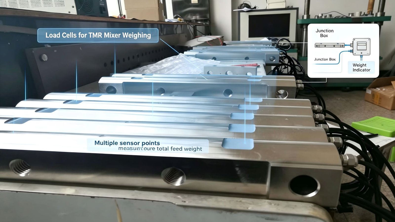
Double-ended shear beam · 1–470 t
WST502 — when the deck is 100 t or heavier
- 1 to 470 t in fourteen steps · output 2.85 mV/V, the highest of the four
- Combined error ±0.05 to ±0.1 %F.S · zero balance ±0.1 %F.S
- Input 4450 ±100 Ω or 1450 ±10 Ω · output 4010 or 1402 Ω
- Safe overload 150 %, ultimate 300 % · IP68 · cable 5 m and 12 m
- Zero temperature effect ±0.05 %F.S/10 °C — 200 kg per 5 K on 8 × 100 t
The cost is two-sided. The high-impedance version is the easiest of the four to parallel and the 2.85 mV/V output buys back signal exactly where a 120 t deck needs it, so at 100 t and 50 kg divisions it computes to 2.850 µV/d and passes comfortably. But its search presence is a real limitation: the title and the permanent link describe press machines and silos and never mention truck scales, so a buyer looking for weighbridge cells will not find this page. The silo and tank version of this arithmetic therefore lives somewhere else on the site, in two places: tank and silo weighing systems for the module side, and grain drying towers for the case where the vessel is a column you cannot see. And its zero temperature effect is 0.05 %F.S/10 °C, which on eight 100 t cells is 200 kg per 5 K. At 100 t and 50 kg that is 4 e — outside the Class III temperature allowance on its own. Use it where its capacity is the point, at 50 kg divisions, with a stable site.
Two cells I deliberately did not put in that grid, and the reasons matter more than the grid itself. There is a double-shear cell in our catalogue whose permanent link contains the word “weighbridge” — the only page on the site that does — and it is a genuinely good bridge cell for pound-market tenders. I left it out of the recommended four because it is offered in 50K, 75K and 100K pound ratings, and every calculation in this article is in tonnes. If your tender is in pounds, ask me for it by name and I will redo the arithmetic in pounds rather than convert at the end, because that is where conversion errors live.
And there is a column cell in our range whose published zero temperature effect is ±0.3 %F.S per 10 °C. That is sixteen times the per-10-K figure WST511 publishes. On eight 30 t cells it would be 360 kg per 5 K. I do not quote it for a weighbridge, and I would rather tell you why than let you find it on our own website and wonder whether I was keeping something from you. It is a legitimate cell for applications where its range and its price are the decision, but temperature is not its strength, and a truck scale outdoors is nothing but temperature.
That is the whole method, and it is not a sales method. It is the reason I can tell you in the first reply that a 10 kg division is not available on your indicator, that your concrete deck costs you 3.96 t on every cell, that the wet box is more likely than the cells to be your fault, and that eight good cells I could have sold you were not what your bridge needed.
Questions I answer before every weighbridge quotation
How many load cells does a truck scale need?
It follows from the platform length, not from the capacity. Published platform tables put a 6 m × 3 m deck on four cells, a 12 m deck on six or eight, and an 18 m to 24 m deck on eight or ten. The reason is stiffness: a long deck on four supports sags in the middle, and a sagging deck cannot be corner-adjusted because the load path changes the moment a truck is not where the weights were placed. Industry practice is roughly four cells to 12 m, six to 16 m, and eight beyond that, with the caveat that eight cells cost 60 to 80 % more than four and take three to four hours to calibrate instead of two.
Why does an 80 t bridge use 30 t cells instead of 10 t?
Because capacity is not divided by the number of cells. The honest formula is C = K0 · K1 · K2 · K3 · (Wmax + W) / N, where W is the weight of the deck itself. On an 80 t bridge with eight cells and a 9 t steel platform, the fixed factors multiply to 1.378 and a dynamic factor of 2.0 gives 30.66 t, which rounds to 30 t. The naive answer — 80 divided by 8, so 10 t — requires a dynamic factor of 0.65, which is below one and therefore means the truck would have to be lifted onto the platform rather than driven onto it. Eight 30 t cells are 240 t of installed capacity, three times the maximum capacity, and that ratio is what a real platform plus real axles produces.
Can I have 10 kg divisions on an 80 t weighbridge?
Sometimes, and the answer is a calculation rather than an opinion. The gate is microvolts per division: 1000 × S × Uexc × d divided by (N × C). Eight 30 t cells at 2.0 mV/V with 10 V excitation gives 1.667 µV/d at 20 kg divisions, which passes. Change the division to 10 kg and it halves to 0.833 and fails; change the excitation to 5 V and it halves again; buy 1.0 mV/V cells and it halves a third way. The cell class is not what stops you — a 30 t class C3 cell on eight cells supports a division down to 7.07 kg. The indicator is what stops you, and it costs far less to check than to discover.
Do I need OIML-approved load cells for a legal-for-trade weighbridge?
You need cells with component-level certificates, and you need them because the platform manufacturer will use them as evidence inside the instrument’s own type examination. But the approval that makes a bridge legal-for-trade is granted to the instrument, held by the platform manufacturer, and confirmed by verification on the installed bridge. In the EU a road weighbridge is a non-automatic weighing instrument under NAWI 2014/31/EU, with EN 45501 giving presumption of conformity and OIML R76 as the technical reference behind it. In China it is a compulsory-verification instrument verified under JJG 539-2016, generally not longer than one year. A component certificate is evidence, not a permission, and that distinction is worth more to you than the certificate itself.
Why does my weighbridge read differently depending on where the truck parks?
Because span errors do not average the way zero errors do. In a parallel group the reading is the true weight plus the sum of the zero offsets, but a span error only appears in proportion to the load that reaches the cell carrying it. An even spread across eight cells divides a 0.10 % cell error by eight; a truck parked over one cell presents it in full. The same 0.10 % cell gives 10 kg when the load is spread and 80 kg when it sits on one cell — a factor of eight. That is why corner adjustment is done with a rolling load rather than a stack of weights in the middle: a calibration test spreads the load, and a truck never does.
Why does my bridge read differently in the afternoon?
Zero error is published per 10 K and it adds. Eight 30 t cells with a 0.0018 %F.S per degree zero effect move 21.6 kg over a 5 K change, which at 20 kg divisions is 1.08 e — already past the legal allowance of 1 e per 5 K, and past the 0.5 to 0.7 e share a separately tested component is normally allowed. Run the WELMEC Guide 2.8 re-zero interval method on it and the drift reaches half a division in about 28 minutes at a 5 K per hour swing. The recipe that works: use cells published per degree with the lowest figure you can find, use a hermetic cell so altitude and humidity are out of the sum, re-zero at the working temperature, and give the junction box shade so the trims are not the warmest parts of the circuit.
Pit-mounted or surface-mounted — does it change the cells?
It changes the environment more than the cell. A surface-mounted deck puts the cells, the cable and the junction box in direct weather and traffic splash; a pit-mounted deck puts them in a hole that collects everything the site hoses off the platform. Both are survivable and both fail in the same place — the junction box, mounted at the low point. What I ask for on either design is a hermetic cell, a box on the pit wall above the cable entries, real glands on every unused port, and drainage that was designed rather than discovered. On a long deck I also ask for six-wire cable, because the excitation leads are then part of the measured circuit and their temperature coefficient is a term you can simply delete.
Can you supply the complete weighbridge?
No, and I would rather say so now than bid on it. I export load cells, force sensors, junction boxes, weighing indicators and weight transmitters, with the matching drawings and the arithmetic in this article. The platform, the foundation, the ramps, the instrument’s type approval, its verification and its calibration certificate belong to the bridge builder and the owner. What I can do is give you the capacity, the microvolt figure, the impedance and the temperature bill as numbers before you pour anything, and tell you in writing which of those numbers your design does not yet satisfy.
Most load cells for truck scales enquiries I receive contain a capacity, a division and nothing else. Tell me the maximum capacity, the longest legal vehicle, whether the deck is steel or steel and concrete, how many cells you planned, the worst axle group your traffic will bring, the division you actually need, what excitation voltage your indicator supplies, and the site altitude. I will send back the cell capacity with the dynamic factor written out so you can challenge it, the microvolt-per-division figure, the group impedance and the temperature bill — and if your requirement belongs to a different instrument, I will tell you that instead.
or write directly to Robin@vektorforce.com
VektorForce · load cells, force sensors, junction boxes and weighing indicators · www.vektorforce.com · Robin@vektorforce.com