


A belt scale weighs material in motion, and the conveyor under the cell owns most of the error.
Load cells for belt scales get bought on the wrong number almost every time. The class you are quoted depends on which regulator is talking, the tolerance you are promised is twice the one the law will test, and the specification that actually decides your accuracy — the stability of the zero — is not on any datasheet. I have spent this year explaining the same three sentences to coal yards, quarries and cement plants. Here they are in one place.
- The one scale whose reading is an invoice and whose belt never stops
- Why two regulators describe the same machine with different numbers
- The limit that decides everything, and that nobody reads
- The conveyor you bolt it to owns most of the error
- Case one: the coal yard that asked me for better cells
- Two cells on one bridge, and the number nobody publishes
- The weighing layer is mine; the machine is not
- Sizing a cell around a belt you did not design
- The cable run that quietly costs you a fifth of a percent
- Case two: the quarry where the cells died every six months
- Case three: the 1.5 tonne per hour line where I said no
- Chain code, test weights, and the only test that proves anything
- What half a percent is worth on five million tonnes
- Which rule book applies where
- Load cells for belt scales: the five parts I would quote
- Seven answers I need before I can size anything
- Questions from conveyor builders and plant engineers
1. The one scale whose reading is an invoice and whose belt never stops
A belt scale is a conveyor that has been taught to keep books. Material rides over a short weighbridge carrying one or more idlers, a load cell assembly measures the force, a speed sensor measures how fast the belt is moving, and an integrator multiplies the two continuously: kilograms per metre times metres per second, summed forever. The output is not a weight. It is a running total of tonnage, and on a barge loader, a rail loading station or a cement kiln feed line, that total is the document people get paid against.
I have now written about three families of weighing machines on this blog, and the belt scale is the strangest of them. At a trade-approved self-service weighing station the reading becomes money in front of a customer, and the whole non-automatic legal chain follows. At a checkweigher the reading only fires a reject gate, which is why the law caps its spread rather than its accuracy. A belt scale combines the worst of both: the reading is money, and there is no operator, and the machine is never allowed to stop. That combination produces a rulebook unlike anything else in weighing, and it is why buying load cells for belt scales is not the same exercise as buying a load cell for a platform.
The first thing to settle is which of two machines you are actually building, because plant engineers say “belt scale” for both. Chinese practice draws the line clearly, and I have found this vocabulary the fastest way to a useful conversation:
| Job | What the machine is for | What it must get right | Legal character |
|---|---|---|---|
| Totalising belt scale (metering, D-1) |
To state how much material passed a point, in total. | The running total, accumulated over a shift or a cargo. | May be a trade instrument. Custody transfer, invoicing, royalties, stock reconciliation. |
| Weigh belt / belt feeder (batching, D-2) |
To hold a target flow rate and trim it, usually feeding a process. | Short-term rate stability and the speed of the control loop. | Usually an internal process instrument. The law only arrives if you declare net content from it. |
| Loss-in-weight feeder | To dose by watching a hopper get lighter. | Resolution at very low flow, where a belt scale has already given up. | A different OIML family (discontinuous totalizing, hopper weighers). |
The same weighbridge hardware can serve either of the first two rows; the difference is what you ask it to be good at, and the law only cares about the first row. The third row exists because of a physical limit I will show you the arithmetic for in section 11 — and it is the reason I turn business away.
The core idea of this article: on a platform scale you buy accuracy. On a checkweigher you buy repeatability. On a belt scale you buy neither, because neither is yours to buy — the conveyor already decided both. What you can buy is the stability of the zero, and that is the specification nobody quotes. Everything else on this page follows from that one sentence.
2. Why two regulators describe the same machine with different numbers
Here is the trap, and I have seen it cost a customer a specification argument lasting three weeks. A belt scale that passes class 0.5 in Europe is sold as a class 0.25 belt scale in the United States. It is the identical machine. Nobody is lying, and nobody is rounding. The two rule books simply decided to name a class after different things.
OIML R50 — the international recommendation for continuous totalizing automatic weighing instruments, adopted in China as GB/T 7721 and enforced there through JJG 195 — divides belt weighers into three classes and names each one after its maximum permissible error in service. Class 0.5 is a machine allowed to be 0.5 percent wrong during ordinary use. The tighter number, half of it, is the tolerance you must meet at verification. American practice under NIST Handbook 44 section 2.21 went the other way and named the class after the verification tolerance. So the American 0.25 class and the OIML 0.5 class are the same performance, written twice.
| Who is talking | How many classes | The classes | What the number refers to |
|---|---|---|---|
| OIML R50 / EU MID Annex VIII, Chapter V | 3 | 0.5, 1, 2 | Error permitted in service. Verification tolerance is half the class number. |
| China, JJG 195-2019 | 4 | 0.2, 0.5, 1, 2 | Error permitted in service, and China added a 0.2 class that R50 does not contain. |
| United States, NIST HB 44 §2.21 | 2 | 0.25, 0.1 | Error permitted at verification. The 0.1 class was added in 2019. |
Two things fall out of that table. First, the class name is a language, not a property of the machine. When a supplier quotes you “class 0.5”, ask which document the 0.5 comes from — you will sometimes find it refers to the in-service tolerance and sometimes to the verification tolerance, and the difference is a factor of two on the number you are being sold. Second, everyone has been extending the ladder at the top. R50 names three classes; China legislated a fourth; the Americans added a 0.1 percent class in the 2019 edition of Handbook 44, which is tighter than anything R50 names at all.
That last development is worth understanding because it moved a market. Until the 0.1 percent class existed, weighing bulk grain for export on a belt conveyor was not permissible at all — the only legal route was a garner system, a bulky static arrangement with a staging hopper, a weighing platform and a take-away conveyor, bolted in as an extra stage in the loading process. A certified 0.1 percent belt scale can now do the same job inline, on the conveyor you already have. In the same spirit, the 2016 edition of Handbook 44 made the enclosed weigh belt eligible for certification as a 0.25 percent device for the first time. Regulation does occasionally move to meet the machine, but it moves slowly, and it moves in whole classes.
A word about vendors quoting 0.125 percent. You will see belt scale accuracy claims of 0.125 percent, and occasionally 0.1 or even 0.05, offered as a headline number with no class attached. Read them as marketing until someone tells you what they are measured against and under what conditions. A belt scale that genuinely held 0.125 percent over a full calibration cycle would be more accurate than a class III non-automatic scale — on a machine whose weighing element is bolted to a rubber belt flapping over greasy idlers in the rain. It happens. It is rare, it is expensive, and it is never the load cell that decides it.
3. The limit that decides everything, and that nobody reads
Every enquiry for load cells for belt scales opens with a capacity, an accuracy class and a cable length. Almost none opens with the zero. That is exactly backwards, and here is the rule that proves it. JJG 195-2019, China’s verification regulation for continuous totalizing belt weighers, adopts OIML R50 and sets the zero tolerance by class:
| Class | Zero accumulation error (percent of the load a full flow would have totalled) |
Maximum deviation with zero load (same basis) |
Phantom mass allowed in a 3 minute empty run at 1,200 t/h |
|---|---|---|---|
| 0.2 | 0.02 % | 0.07 % | 12 kg |
| 0.5 | 0.05 % | 0.175 % | 30 kg |
| 1 | 0.1 % | 0.35 % | 60 kg |
| 2 | 0.2 % | 0.7 % | 120 kg |
Read the middle column as an instruction: run the belt empty for a whole number of revolutions, and the totalizer must not pick up more than 0.05 percent of what full flow would have delivered in the same period. On a 1,200 t/h conveyor, over three minutes, that is 30 kilograms of nothing. That is the legal allowance. The right-hand column is the companion test, and it is there for a reason people rarely spot: a maximum deviation under zero load is really a check on belt thickness uniformity. The regulation says as much, which is why, if you splice in a short replacement section of belt, you must match the thickness of what you took out. A thick patch is a permanent, invisible, unzeroable offset.
Why is the standard so preoccupied with the empty belt? Because of a mechanism unique to this machine, and the Chinese literature states it bluntly: the zero error is accumulated once for every complete revolution of the belt, and then it accumulates again on the next revolution, and the next. A belt scale does not make one measurement and then ask you to accept it. It makes a measurement every revolution, all shift, and adds the results. A zero offset of a few grams of force per metre does not stay a few grams. It becomes a number of tonnes by the end of the day.
The second test is the one that should worry you. R50 and JJG 195 also require a short-term zero stability test: zero the scale, run it empty for fifteen minutes, take a reading every three minutes, and the spread between the smallest and largest readings must remain inside 0.0018 percent of the accumulated load at maximum flow over an hour. On the same 1,200 t/h machine that is 21.6 kilograms of phantom tonnage in a quarter of an hour. Now translate that into a force, because force is what I sell.
The scale’s arithmetic is Q = 3600 × F × v / L, where Q is tonnes per hour, F is the force on the weighbridge in kilograms, v is belt speed in metres per second and L is the weigh length in metres. Invert it for a drift: ΔF = ΔM × L / (v × T). With the 21.6 kg above, L = 4.8 m, v = 3.0 m/s and T = 900 s: ΔF = 0.038 kg.
Thirty-eight grams. On a weighbridge carrying 533 kilograms of live load and roughly 230 kilograms of belt and deck as permanent dead load, supported by two 1,000 kilogram load cells. As a fraction of the cell pair’s capacity the legal allowance for a quarter of an hour is 0.0019 percent of full scale. And measured against the number that appears on every load cell datasheet — zero temperature effect, typically 0.02 percent of full scale per 10 degrees Celsius, which is 0.2 kg per cell per 10 degrees, or 0.4 kg for a well-behaved pair — the legal allowance is worth 0.96 degrees Celsius.
The legal zero budget on a belt scale is about one degree Celsius per quarter of an hour. An ambient swing of one degree in fifteen minutes consumes the entire allowance the standard gives you for zero drift — before the belt has done anything, before the wind has done anything, before a single gram of carryback has stuck to an idler. That is not a reason to distrust the standard. It is a reason to understand that on this machine the load cell is rarely the binding constraint, and the things around it usually are.
There is one lever here that costs nothing to pull. That 0.4 kg per 10 degrees is the worst case — it assumes the two cells’ zeros wander in opposite directions, one up and one down. Ask your supplier for a matched pair: two cells whose zero temperature coefficients sit within 0.005 percent of full scale per 10 degrees of each other. The pair drift drops to 0.05 kg per 10 degrees, and the same 0.038 kg allowance suddenly buys you 7.7 degrees Celsius per quarter of an hour. Eight times the budget, for the price of asking for it in writing.
I want to be plain about something here. Our own product pages give the zero temperature effect as a single cell number and say nothing whatsoever about how closely two cells in a pair match each other. So does everyone else’s. It is the most useful specification you can ask a load cell supplier for on a belt scale, it is not on a datasheet, and on this application it matters more than the accuracy class. If you take one practical thing from this article, take that one.
The American framework asks a related but looser question. Handbook 44 section 2.21 requires a zero-ready indicator and demands that zero balance be held within 0.12 percent of rated capacity before a commercial transaction — about 0.64 kg of force on our 1,200 t/h conveyor, some seventeen times the OIML-style fifteen-minute allowance. The comparison is not quite apples to apples, and that is exactly why it is instructive: one rule asks is the zero in the right place? and the other asks is the zero holding still? A machine can pass the first comfortably and fail the second, and the second is the one that costs you tonnage.
| What moves the zero | How big it is on this machine | Whose problem it is |
|---|---|---|
| Load cell zero temperature coefficient, unmatched pair | 0.4 kg of force per 10 °C — the whole legal budget at 1 °C per 15 min | Mine, but only if you ask for a matched pair |
| Matched pair, zero coefficients within 0.005 %FS/10 °C | 0.05 kg per 10 °C — 7.7 °C of budget per 15 min | Mine. Specify it at the enquiry, not at the complaint |
| Cell creep under a permanent preload | Not on any datasheet, because no datasheet assumes the load never comes off | Mine, and it is why a belt scale cell is chosen differently from a platform cell |
| Belt stiffness and thickness changing with temperature | Unbudgeted, and often larger than everything above combined | Conveyor builder and belt supplier |
| Carryback and material build-up on belt and idlers | Unbudgeted, grows all shift, resets when someone cleans | Site maintenance. A scraper is a metrological device |
| Wind on an uncovered belt in the scale area | Unbudgeted and unbounded. It is lift, not weight, and it does not average to zero | Conveyor builder and site |
| Idler bearing drag and grease condition | Unbudgeted, and changes the moment someone relubricates | Site maintenance |
Two lines in the two rule books make all of this worse in a way that deserves its own sentence. The EU Measuring Instruments Directive requires that a continuous totaliser’s general totalisation device cannot be reset to zero. Handbook 44 requires that the master weight totalizer cannot be reset without breaking a security seal, and that the reset is inhibited until the total has been printed. Put those together and you get the operating reality of this machine:
You may zero the bridge. You may not zero the total. Which means a zero error that creeps in at eight in the morning is still being invoiced at four in the afternoon, and every gram of it became tonnage the moment it entered the register. On a platform scale a drifting zero is a nuisance you correct. On a belt scale it is revenue already booked.
4. The conveyor you bolt it to owns most of the error
I keep a list of what has to be true before a belt scale can work. It has fourteen items on it. Exactly none of them is about the load cell. They are about idlers, stringers, the loading point, the belt itself, and the air. When a customer tells me their belt scale is “inaccurate” and asks for a better sensor, this is the list I send back before I quote anything. It is also why I can rarely answer an enquiry about load cells for belt scales with a price.
| What has to be true | The number | What it protects |
|---|---|---|
| Alignment of the scale idler and its neighbours | Within ±0.8 mm (1/32 in) of each other, checked with a taut wire at both ends of each roll | A step under the belt tilts the load path and applies a force nobody asked for |
| Quality of the idlers in and around the scale | Scale-quality idlers aligned to 0.5 mm, not “selected from production” | Roll run-out is a periodic force at belt-rotation frequency, and the totalizer sums it |
| Number of idlers you must actually buy | Eleven for a single-idler scale, twelve for a dual-idler scale: one or two on the bridge, five on the approach, five on the retreat | The bridge cannot be flat if the belt arrives on a ridge |
| The scale idler must never sit lower than its neighbours | Set the idler last, leaving it around 0.75 mm high | A low idler sheds load and the scale under-reads permanently |
| Rigidity of the conveyor stringers in the scale area | Relative deflection limited to 0.8 mm; mount close to a vertical support where deflection is near zero | If the frame moves, the cell measures the frame instead of the material |
| Distance from the loading point | At least 6 m or five idler spaces from loading points and pulleys | Impact and turbulence upstream; the bed has to settle before it is weighed |
| Position of any belt training idler | Not within 18 m of a weighing idler | A training idler pushes sideways and creates a lateral load on the bridge |
| Trough angle consistency | 20 or 35 degrees, and the same on every idler in the conveyor | The bed shape has to be identical before and after the bridge, or the load distribution shifts |
| Belt contact with the wing rollers | The belt must stay in contact with the centre and both wing rollers of every aligned idler | Partial contact means the belt is spanning the idler, and the geometry stops being predictable |
| Shelter from wind | Cover the conveyor top and sides for at least 9 m each side of the scale idlers, sides extending about 0.6 m below the return belt | Wind produces lift, and lift does not average to zero over a shift |
| Overload stops | Clearance around 0.5 mm, set so the bridge cannot travel far enough to overload the cells | The stops are the cells’ only protection, and nobody ever checks them |
| What may be attached to the weighing idler | Nothing. No conduit, no cable tray, no junction box resting on it | Anything resting on the weighing idler is being weighed, permanently |
| Warm-up before anything is measured | Run the conveyor empty until the belt is limbered, 20 to 30 minutes where possible | A cold belt has different stiffness and tracks differently from a warm one |
| Re-check interval for alignment | Annually, plus after any splice, roller change or foundation work | Alignment is not a commissioning event; it decays |
Look at the third row of that table again, because it is the sentence I most often have to say out loud to a purchasing department. A dual-idler belt scale needs twelve scale-quality idlers. Two load cells. The idler bill is six times the cell bill, and the idlers are not a component of my product. Nobody ever bought a belt scale because of a load cell. They bought it because of eleven scale-quality idlers and a piece of taut string.
Two more numbers govern whether the machine is even in its design range. A belt scale is expected to operate between 20 and 100 percent of rated capacity; American practice goes further and requires the rate-of-flow indicator to signal audibly or visually when flow drops to 20 percent or reaches 100 percent, because those are the boundaries of the region where the instrument means anything. And the belt speed must not vary by more than 5 percent of nominal for a single-speed belt weigher — which sounds like a generous allowance until you notice what it implies. If you do not measure the speed and instead type a nominal figure into the integrator, then every deviation you are permitted to have becomes an error in the mass total. Five percent of speed error is five percent of tonnage error. That is twenty times the tolerance a class 0.5 machine must meet at verification.
Fit a speed sensor even on a fixed-speed drive. Rolling resistance changes with load, the belt slips on the head pulley when it is wet, and supply voltage moves the drive. Manufacturers of belt scales say the same thing in their own manuals: conveyor speed is virtually never constant. The cheapest accuracy improvement available on any belt scale is the speed sensor you were thinking of leaving out.
5. Case one: the coal yard that asked me for better cells
In March this year a coal handling contractor in Kalimantan, Indonesia, sent me an enquiry that I have now received in some form from four continents. Their barge loading conveyor ran at 1,200 tonnes per hour on a 1,200 mm belt at 3.0 metres per second, the weighbridge carried four idlers at 1.2 metre spacing, and their belt scale was reading about 1.5 percent away from the draft survey when they compared a loaded barge against the totalizer. They wanted to know the price of a matched pair of high-accuracy cells, and they were specific: something in the 0.02 percent class, stainless, IP68.
The arithmetic says their request was reasonable on its face. Live load is 111 kilograms per metre across a 4.8 metre weigh length, so about 533 kilograms sitting on a bridge whose cells were rated 1,000 kilograms each. A 1.5 percent error is enormous compared with the 0.25 percent a class 0.5 machine must hold at verification, and a better cell is the obvious first suspect.
So I asked for seven photographs and two measurements instead of sending a quotation. The photographs were: the weighbridge from both sides, the approach idlers, the loading point, the belt splice in the scale zone, and the sky above the scale. The measurements were: a string line across the tops of the five idlers around the bridge, and the run-out on the approach idlers.
What came back explained the whole 1.5 percent, and none of it was the cells:
- The weighing idler sat 3 mm high against the retreat idler. The tolerance is 0.8 mm.
- The two approach idlers were ordinary production idlers with about 1.5 mm of roll run-out, not scale-quality.
- One idler in the weighing area was a 20 degree trough while every other idler on the conveyor was 35 degrees.
- The loading point was 4 metres upstream of the bridge. Handbook 44 wants 6 metres or five idler spaces.
- A belt training idler sat 6 metres upstream. The exclusion zone is 18 metres.
- The scale was completely uncovered on an open jetty, and the site is a coal terminal on a coastline.
- There were three splices inside the weighing area, at least one of which had a visibly thicker patch.
- The load cell cable ran 140 metres back to a cabinet, on four wires.
I did not sell them cells that month. I sent them a work list: re-shim the five idlers to within 0.8 mm on a string line, leave the scale idler a fraction high, replace the approach and retreat idlers with scale-quality units, change the odd idler to 35 degrees, move the training idler out of the 18 metre zone, move the loading point to at least 6 metres, cover the belt for 9 metres each side of the scale with the side sheeting dropping below the return belt, replace the spliced section with belt of matched thickness, move the junction box onto the conveyor frame and shorten the four-wire run to the cabinet, and then run a material test rather than trusting the old calibration.
They did it over a two-week shutdown. The error came down from roughly 1.5 percent to 0.28 percent, on the original cells. That is a factor of five, from eleven idlers and a string line, and it is not good enough for class 0.5 — the verification tolerance there is 0.25 percent, and 0.28 percent is just outside it. It is comfortably inside class 1 at 0.5 percent.
Only at that point did we have a useful conversation about sensors. Now the question was not “can a better cell fix my scale” — the answer to which was no — but “can I get from 0.28 to under 0.25 without rebuilding the plant”. That is a question a matched pair can genuinely answer, because the remaining error was dominated by exactly the term I described in section 3: the difference in zero behaviour between two cells that had never been matched to each other. We shipped a matched pair with the zero and span differentials written on the certificate, and on the next material test they read 0.19 percent. Class 0.5, with a little margin.
What that job taught me, and what I now say first: on a belt scale, buy the conveyor before you buy the cell. The order of operations that works is alignment, then idlers, then the loading point, then shelter, then the cable run, then a material test to establish where you actually are — and only then a matched pair, justified by the residual error you measured rather than the residual error you feared. It is also the honest answer to most enquiries about load cells for belt scales: the sensor is the last decision, not the first.
6. Two cells on one bridge, and the number nobody publishes
A weighbridge almost always stands on two load cells, one at each end of the transverse member, wired in parallel so the instrument sees their combined signal. That parallel connection creates a class of error that does not exist on a single-cell scale, and it comes from a specification everybody ignores: the difference between the two cells.
Think about what the instrument is calibrated against. It is calibrated with a known load, applied wherever the calibration rig happens to apply it — usually centrally, so both cells share the load equally. That calibration builds a single scale factor into the instrument, and that factor is an average of the two cells’ sensitivities. Now run the conveyor. The material sits slightly off centre, because the belt tracks a few percent of its width to one side, because the loading point is not perfectly symmetrical, because one stringer is stiffer than the other. The load splits unevenly between the two cells, and the asymmetric parts of their sensitivities no longer cancel. The error works out to a beautifully simple product:
Error = ½ × (load imbalance between the two cells) × (output mismatch between the two cells)
| Load imbalance | Cell pair matched to 0.05 % | Matched to 0.1 % | Matched to 1 % | Two cells from opposite ends of a ±7.5 % band |
|---|---|---|---|---|
| 5 % | 0.001 % | 0.003 % | 0.025 % | 0.19 % |
| 10 % | 0.003 % | 0.005 % | 0.05 % | 0.38 % |
| 20 % | 0.005 % | 0.01 % | 0.10 % | 0.75 % |
Read the right-hand column, because it is where projects die. A pair of cells matched to one percent — which is a perfectly ordinary pair of good cells, if nobody has matched them — with a twenty percent transverse imbalance, costs you 0.10 percent. That is forty percent of the entire class 0.5 verification budget, spent on a term that appears on no specification sheet. Move to two cells drawn from the outer edges of a wide output tolerance band and the same twenty percent imbalance costs you 0.75 percent, three times the whole budget, from a pair of cells that each individually passed every test on their certificate.
Here is the part that catches people out, and it is the reason I always read the output tolerance line on a competitor’s datasheet before their accuracy line. A rated output of “2.0 ± 0.15 mV/V” sounds like a wide tolerance, and it is: that is a band seven and a half percent wide. It sounds alarming and it is completely normal, because on a single cell the absolute output value is absorbed by the instrument’s calibration. You calibrate the scale against a test load and the factor disappears. On a pair, the absolute values cancel too — but the difference between them does not. Which means the number you need is not on the datasheet at all, and it is not the same number as the tolerance band.
The junction box exists precisely for this. A multi-channel summing box carries trimming potentiometers that adjust the excitation reaching each cell, so you can bring two cells’ spans into agreement on site. I supply those boxes and I recommend them without hesitation. But be clear about the boundaries of the technique. Trimming adjusts the span and leaves the zero alone. It changes the excitation the cell runs at, so the two cells no longer share the same self-heating and the same thermal environment. And it cannot exceed its trim range — you cannot trim a cell whose output is seven percent off nominal back into a matched pair, because the trim runs out first. The junction box is for the last tenth of a percent, not for the first percent.
And the zero cannot be trimmed at all. Back in section 3 the arithmetic said the pair’s zero drift is what decides your accuracy, and the zero is the one thing the junction box cannot touch. That is the whole reason a matched pair is worth buying rather than assembling. It is also why the question to put in writing is not “what is your accuracy class” but “what is the zero temperature coefficient difference between the two cells you are shipping me?” Expect a blank look the first time. Ask anyway, and ask for it on the certificate.
7. The weighing layer is mine; the machine is not
This article has spent three sections telling you that the load cell is not the main problem. It would be a strange way to sell load cells if I did not now say exactly what I do sell, and where the boundary sits. I export weighing components: load cells, force sensors, junction boxes and weighing instruments, with test data and application advice. I do not build belt scales, and I am not a systems integrator. The distinction matters commercially, because a project that assumes I am the second thing will discover I am the first thing at an inconvenient moment. Anyone quoting load cells for belt scales should be able to draw that boundary in a single sentence.
| I supply this | I do not supply this |
|---|---|
| Load cells and force sensors, with capacity, class and temperature data | The weighbridge, the weigh frame, the lever or counterbalance design |
| Matched pairs on request, with the zero and span differentials on the certificate | The conveyor, the stringers, the scale-quality idlers, the belt |
| Junction boxes with surge protection and trim potentiometers | The speed sensor, the totalising integrator, type approval of the complete instrument |
| Weighing indicators, controllers and transmitters | The enclosure design, the wind shelter, the material test facility, the seals and the verification |
| Mounting and wiring advice, dwell and capacity arithmetic on your numbers | Calibration service, commissioning, warranty of the machine as sold, any safety-rated function |
| The load cell module certificate, and a calibration certificate per serial number | The instrument approval. Under MID that certificate belongs to the manufacturer of the complete belt weigher |
Two of those left-hand rows are worth enlarging. The right-hand column is not modesty and it is not a disclaimer — it is the reason the rest of this article is useful. I have no commercial interest in whether you fix your idler alignment, because I do not sell idlers, and I have no interest in whether you cover your conveyor, because I do not sell covers. When I tell you that the idler bill is six times the cell bill, you can take it at face value.
And the matched pair is the one place where the component supplier genuinely owns the outcome. Everything else in this article belongs to the conveyor, the site or the integrator. The zero drift of the pair, the span match, the creep under a belt that never leaves the cell — those are mine, they are decided in my factory, and they are the reason a belt scale customer should be talking to a load cell maker at all rather than simply ordering from a catalogue. There is more on how I approach that kind of component-level work in my selection guide, and on what happens when a weighing element fails, in the fault-finding note I wrote after getting the same question from three plants in one month.
8. Sizing a cell around a belt you did not design
Sizing load cells for belt scales starts from a quantity most people have never calculated: how much material is sitting on the belt, per metre, right now. The scale’s own arithmetic gives it to you directly. From Q = 3600 × q × v, where Q is tonnes per hour, q is kilograms per metre and v is belt speed in metres per second, you get q = Q divided by 3.6 v.
| Capacity | Belt speed | Material on the belt | Live load on a 4-idler bridge at 1.2 m spacing |
|---|---|---|---|
| 100 t/h | 1.25 m/s | 22.2 kg/m | 107 kg |
| 300 t/h | 2.0 m/s | 41.7 kg/m | 200 kg |
| 600 t/h | 2.5 m/s | 66.7 kg/m | 320 kg |
| 1,000 t/h | 3.0 m/s | 92.6 kg/m | 444 kg |
| 1,200 t/h | 3.0 m/s | 111.1 kg/m | 533 kg |
| 1,500 t/h | 3.15 m/s | 132.3 kg/m | 635 kg |
| 2,000 t/h | 4.0 m/s | 138.9 kg/m | 667 kg |
Now add what is always there. The belt itself, the weighing idlers and the floating deck sit on the bridge permanently, whether material is flowing or not. On our 1,200 t/h conveyor that is roughly 230 kilograms of dead load on top of the 533 kilograms of live load. The cells carry it 24 hours a day, including through the night when the plant is idle, and that has a consequence that no platform-scale datasheet anticipates: the cell is permanently preloaded, so whatever creep the element has under that preload becomes a standing zero offset that never relaxes. On a platform scale the load comes off between weighings and the element recovers. On a belt scale it never does. The offset has to be taken out by the zero-setting device, which is exactly why the rule books insist on a zero-setting device and a zero-ready indication in the first place.
So capacity has to cover dead plus live plus shock, and here is where the belt scale fights itself. Look at what happens to the zero budget as you increase the cell size, holding the live load fixed at 533 kilograms and assuming two cells whose zeros drift in opposite directions at the ordinary 0.02 percent per 10 degrees:
| Cell pair | Burden per cell (live + dead) | Pair zero drift | Ambient swing that uses the 15 minute legal budget |
|---|---|---|---|
| 2 × 500 kg | 76 % — too little headroom for shock | 0.20 kg per 10 °C | 1.9 °C |
| 2 × 1,000 kg | 38 % | 0.40 kg per 10 °C | 0.96 °C |
| 2 × 1,500 kg | 25 % | 0.60 kg per 10 °C | 0.64 °C |
| 2 × 2,000 kg | 19 % | 0.80 kg per 10 °C | 0.48 °C |
| 2 × 3,000 kg | 13 % | 1.20 kg per 10 °C | 0.32 °C |
Every step up in capacity that buys you structural headroom costs you zero stability, in direct proportion. Going from 1,000 to 2,000 kilogram cells takes the burden from 38 percent to 19 percent — comfortable, no risk of shock damage — and halves your legal zero budget from 0.96 to 0.48 degrees. There is no cell specification that resolves this, because the two requirements pull in opposite directions on the same number. The only way out is to make the dead load smaller, which is a mechanical problem: stiff, light, counterbalanced weigh frames exist precisely to keep the tare off the load cell, and on high-accuracy machines the frame is explicitly mass-counterbalanced so the cells see a small fraction of the belt’s weight. That design is the machine builder’s, not mine.
Every kilogram of belt is a kilogram of load cell you did not need, and a kilogram of zero drift you cannot zero out. That sentence is the whole capacity argument on a belt scale, and it is why I ask for the belt weight per metre and the idler weights before I ask about accuracy.
There is a second floor under the machine, and it is measured in mass rather than time. R50 and the EU directive both define a minimum totalised load: class 0.5 may not certify a total below 800 scale intervals, class 1 below 400, class 2 below 200. The interval itself is bounded too — it must lie between 0.01 and 0.2 percent of maximum capacity, and Handbook 44 says the same thing from the other side, that a scale division may not exceed 1/800 of the minimum totalised load. Those are not two rules; they are one rule read from opposite ends. Put a one kilogram interval on our machine and both agree it is legal, with the minimum totalised load landing at exactly 800 kilograms.
| Flow rate | Time to accumulate the legal minimum of 800 kg | What that means in practice |
|---|---|---|
| 1,200 t/h | 2.4 seconds | Irrelevant. Everything you will ever certify is far above the floor. |
| 300 t/h | 9.6 seconds | Still irrelevant for a shipment total. |
| 100 t/h | 28.8 seconds | Fine for a shift or a silo fill. Not fine for a single truck load. |
| 20 t/h | 2.4 minutes | Also below the 20 percent flow floor on most conveyors. Now you are outside two limits at once. |
| 2 t/h | 24 minutes | You cannot legally state a total in under a third of an hour. This is the design case I turn down. |
Read that table slowly, because it contains a trap. On a fast conveyor the minimum totalised load passes in two and a half seconds and you will never think about it again. On a slow one the same legal floor takes twenty-four minutes — and since the 20 percent flow floor bites in exactly the same region, a low-flow belt scale fails two independent requirements at once. That is the arithmetic behind section 11.
9. The cable run that quietly costs you a fifth of a percent
The cabinet on a minerals plant is never next to the scale. It is 100 metres away in a control room, on the other side of a road, and the load cell signal has to get there. That distance is a metrological component, and it is one of the few places in this article where a decision made purely on price shows up in the accuracy certificate.
The classic arrangement is four wires: two carry the excitation out and two carry the signal back. The excitation current flows through the cable, so it loses voltage on the way out, and the loss depends on the cable’s resistance. For 100 metres of 0.5 mm² copper, the loop adds about 6.9 ohms in series with the cell’s 380 ohm bridge. Copper’s resistance rises by about 0.39 percent per degree Celsius, so when the cable warms by 20 degrees the series resistance grows by almost 8 percent, and the fraction of the excitation lost in the cable grows with it. The scale factor moves with the cable. The effect is small and it is not negligible:
| Arrangement | Excitation lost in 100 m of cable | Span change over a 20 °C cable swing | Share of the class 0.5 verification tolerance |
|---|---|---|---|
| 4-wire, 350 Ω bridge | 1.93 % | 0.151 % | 60 % |
| 4-wire, 380 Ω bridge | 1.78 % | 0.140 % | 56 % |
| 6-wire with sense leads | Regulated out at the cell | 0.000 % | 0 % |
Fifty-six percent of your entire legal tolerance, spent on the temperature of a cable. Two observations worth carrying away. First, a higher bridge resistance helps: the 380 ohm input resistance on the cells I recommend is slightly better here than a 350 ohm bridge, because a larger bridge makes the cable’s series resistance a smaller fraction of the loop. Second, and counter-intuitively, lowering the excitation voltage does not help — the loss is a ratio of cable resistance to total loop resistance, so running the cell at 5 volts instead of 10 leaves the percentage unchanged.
The fix is not a better cell, it is a different architecture, and it is why I quote load cells for belt scales together with a junction box and a transmitter rather than as a bare part number. My recommendation for any run beyond a few metres: mount the WST1513 multi-channel junction box on the conveyor frame within sight of the weighbridge, bring the cells into it on short leads, and from there run either a six-wire cable with sense leads or convert to a current loop at the scale. A WST1508 transmitter does the conversion: 4 to 20 mA, 0 to 10 V, isolated RS485 with Modbus RTU, up to twelve 350 ohm cells, and an operating range from minus 10 to 40 degrees that matches what the rule books expect of the installation. Once the signal is a current loop, cable resistance is somebody else’s problem.
One more thing about where the junction box goes. Put it on the conveyor frame, in the scale area, at the end of a short run — but never resting on the weighing idler or its support. Anything mounted there is being weighed, permanently, and it will appear in every total you ever print. This is in the belt scale manufacturers’ own installation manuals, in exactly those words, and it is the single most common mechanical error I see in photographs of new installations.
10. Case two: the quarry where the cells died every six months
The second case is not about accuracy at all. It is about a hard-rock quarry in the Middle East that had replaced the load cells on one belt scale four times in two years, at roughly six-month intervals, and was starting to believe the cells were simply poor quality. They were our cells, so I took it seriously.
Their conveying duty was 900 tonnes per hour, and the pattern was informative: the failures were mechanical, on the same cell each time, and they followed rainy season. That combination — same cell, seasonally correlated, mechanical rather than electrical — told me to look upstream of the bridge, so I asked two questions: where does the truck tip relative to the scale, and what is the gap on the overload stops?
The loading point was 2.5 metres from the weighbridge. The band was recommending 6 metres, and Handbook 44 wants 6 metres or five idler spaces, and both of them mean the same thing: a skip of 20 tonnes of rock landing on a belt produces a travelling wave that has to be absorbed by the bed and the stringers before anything can be weighed. At 2.5 metres the wave was arriving at the weighbridge almost intact, on every load, all day. And the overload stops were set with 4 millimetres of clearance where the manual calls for about half a millimetre — eight times too much travel. The stops were supposed to catch exactly this event and they were never in a position to touch it. The cell was doing the job the stops were designed for, four times a year.
Two changes fixed it, and neither was a specification. They moved the scale downstream so the loading point sat beyond six metres, and they re-set the overload stops to the specified clearance. We also changed the cell model on the next order, not for accuracy but for overload margin: our large single-point WST204 is rated for 120 percent safe overload, which is generous on a floor scale and thin on a belt scale, whereas the WST303 and WST401 carry 150 percent. That difference exists on our own pages, it is the kind of thing that gets lost between a purchasing list and a drawing, and on this duty it is worth more than an accuracy class.
On a belt scale the load cell is a structural part of the conveyor. It is not a sensing accessory bolted on at the end. Its overload rating is a maintenance interval, not a line on a datasheet, and its most common failure mode is not drift or damage from age — it is being asked to survive an impact that the mechanical design was supposed to absorb.
11. Case three: the 1.5 tonne per hour line where I said no
The third case is the one I am least comfortable writing, because the customer was right about everything except the machine. A sand and dry-mortar plant in Southeast Asia wanted a belt scale on a short conveyor handling about 1.5 tonnes per hour, running at 1.25 metres per second, and asked me to recommend cells for it. Their previous integrator had told them the problem was resolution at low flow and that a high-resolution digital cell would solve it.
Run the numbers and the machine disappears. At 1.5 t/h and 1.25 m/s the belt carries 0.33 kilograms per metre. Over a single idler at 1.2 metre spacing, the live load on the weighbridge is 0.4 kilograms. Against roughly 120 kilograms of belt and idler dead load. The dead load is three hundred times the live load, and the live load is four hundredths of one percent of the capacity of a pair of 500 kilogram cells.
Now put the zeros back in. That pair of 500 kilogram cells carries 0.2 kilograms of zero drift per 10 degrees Celsius of ambient change — with a good unit, on a normal day. Relative to a 0.4 kilogram signal, the zero drift is fifty percent of the reading, per 10 degrees. There is no cell on the market that changes this. A load cell’s zero stability is proportional to its capacity; the signal on a belt scale is proportional to the flow. Push the capacity down to help the ratio and the belt’s own dead weight exceeds the cell’s rating; push the flow up to help the ratio and you are no longer building the plant the customer has.
I worked out what it would take for the live load to reach even twenty percent of the cell capacity — a modest ambition — and the answer was about 750 tonnes per hour. Five hundred times their actual flow. At that point I stopped looking for a cell and told them the truth: a belt scale cannot weigh 1.5 tonnes per hour, not because belt scales are inaccurate but because at that flow the weighing element is trying to detect a few hundred grams sitting on a moving rubber belt that weighs a hundred times more, in wind, with the belt stiffness changing all day.
What they needed was a different machine. A loss-in-weight arrangement — a hopper on load cells, discharging through a feeder — puts the entire hopper content on the weighing element, so the live load becomes tens of kilograms instead of hundreds of grams, and the same cell that was hopeless on a belt becomes perfectly adequate. We quoted cells for the hopper instead, and a small junction box, and their existing supplier kept the feeder. That is the correct outcome and it is also the one that cost me a larger order.
The most common belt scale mistake is not a wrong load cell. It is a belt scale. Before anyone specifies sensors, ask the question that decides everything: what fraction of the cell’s capacity does the material represent, and what fraction does the belt represent? If the second number is a hundred times the first, the sensor is not the problem and no sensor is the solution. That is why I ask for the flow and the belt weight before I will discuss load cells for belt scales at all.
12. Chain code, test weights, and the only test that proves anything
A belt scale cannot be calibrated with a dead weight, because it does not measure a dead weight. It measures a moving bed. The industry solves this in two families of method, and the difference between them is the difference between proving a machine repeats and proving it is right — two entirely different claims that get confused constantly.
| Method | What it is | What it actually proves | What it cannot prove |
|---|---|---|---|
| Hanging or bar weights | Known masses suspended from or laid on the weighbridge, applied as a load per metre | That the bridge responds correctly to a static force, and that the electrical chain works | Anything about belt stiffness, bed shape, or how material actually behaves on the belt |
| Chain code and loop chain | A calibrated chain lying along the belt through the scale zone, applying a distributed load per metre | Repeatability under a distributed load, and the shape of the bridge’s response curve | Absolute trueness. A chain is not material and does not sit in the belt the way material does |
| Material test | Actual product, weighed on an independent reference such as a certified truck scale or a calibrated hopper | That the machine’s total agrees with the truth for the product you actually convey | Nothing. It is the reference, and this is why the rule books require it |
The size of the gap between a simulated load and the real thing is genuinely uncomfortable. One published comparison on a belt scale of ordinary commercial quality found chain-code calibration and material calibration stable within about 3 percent of each other once the zero had been properly set — twelve times the tolerance a class 0.5 machine is allowed at verification. I would not want that single figure to be read as a general law, and I have no doubt that a well-installed scale on a modern weigh frame closes the gap far further. But the ranking is not in doubt and it is what matters: a chain code proves your machine repeats. Only material proves it is right.
One arithmetic detail from the manufacturers’ manuals that makes weight calibration less arbitrary than it looks. When you calibrate with test weights, the number you enter into the integrator is not the total weight of the weights. It is the total weight divided by the idler spacing, expressed in kilograms per metre — the same units as the q in section 8. Stack 1,200 kilograms of test weights on a bridge with 1.2 metre idler spacing and you are telling the instrument it is looking at 1,000 kilograms per metre, which is what a full conveyor would put on it. Get that division wrong at commissioning and every total from then on is wrong by the same factor, which is at least a diagnosable failure and better than a drifting one. None of this has anything to do with load cells for belt scales, and that is the point: the cell is calibrated out of the conversation and the conveyor is calibrated into it.
Frequency matters more than method, and here the guidance from people who operate these machines for a living is more aggressive than most plants expect. The recommended rhythm, drawn from Chinese practice and consistent with what belt scale manufacturers put in their manuals:
| What | How often | Why that interval |
|---|---|---|
| Zero calibration | Daily | The zero is the whole budget, per section 3, and it moves with temperature and carryback |
| Span / interval calibration with a simulated load | Monthly | Catches mechanical drift in the frame and idlers before it becomes a class change |
| Material calibration | Every three months | The only method that establishes trueness, and the only one that catches a change in the product |
| Material calibration, where a reference facility exists | Weekly | If you own the means to do it properly, the cost of doing it often is trivial against the cost of being wrong |
| Idler alignment check | Annually, and after any splice or roller change | Alignment decays silently and is invisible on the instrument until the totals drift |
| Verification by the authority | Per the local cycle | Not a substitute for the above. The literature is unambiguous that an annual verification tells you nothing about the other 364 days |
Two procedural habits come from the belt scale manuals and I recommend both without qualification. Run two calibrations before adjusting anything, and only accept the result if the two agree — because a single calibration on this machine tells you nothing about whether you just measured the scale or measured the weather. And run the conveyor empty for 20 to 30 minutes before zeroing, because a cold belt has different stiffness and tracks differently from a warm one, and you are about to define zero on whichever belt you happen to have that morning.
The record keeping is part of the legal instrument, not an administrative afterthought. Handbook 44 requires a belt-conveyor scale system to record the unit of measurement, the date and time, the initial and final indications of the master weight totalizer and the quantity for each delivery; to retain accumulated quantities through a power loss of up to 24 hours; and to keep calibration, maintenance and test records for at least three years. If you are buying an indicator for a legal-for-trade belt scale, that list is your minimum functional specification, and date and time stamping is not optional.
13. What half a percent is worth on five million tonnes
Half a percent sounds like nothing, and on a kitchen scale it is. On a bulk terminal it is a line in the annual accounts, because accuracy class on a belt scale is not a quality attribute, it is a price. It is also why the class you pick for your load cells for belt scales turns up in the annual accounts rather than in a maintenance report.
| Throughput | Tonnage at risk on a 0.5 % error | At 100 USD per tonne | What moving to a 0.25 % class recovers |
|---|---|---|---|
| 5,000,000 t per year | 25,000 t | 2,500,000 USD | 1,250,000 USD per year |
| 5,000,000 t, at a 0.1 % class | 5,000 t | 500,000 USD | A further 750,000 USD against the mid class |
That is the arithmetic that explains the class ladder I described in section 2. Nobody added a fourth Chinese class or an American 0.1 percent class because engineers enjoy precision. They added them because at these tonnages the classes are separated by millions of dollars a year, and because the same error appears on the other side of the transaction too. Belt scale manufacturers make the point from the loading side: overfilling rail cars and trucks by two to three percent because the scale under-reads is a routine and invisible loss, multiplied across hundreds of loads, before anyone mentions customer disputes or regulatory fines.
This is also why I am sceptical of headline accuracy claims, as I said in section 2. A number means something only when it comes with a class, a calibration method and a maintenance regime. A machine reading 0.15 percent today on a weigh frame nobody re-aligns can easily be worse in service than a modest class 1 machine that gets its daily zero and its quarterly material test. On this application the maintenance regime is worth more than the class, and it is the cheapest thing on this page to buy.
14. Which rule book applies where
A belt scale crosses several rule books, and the most common mistake I see in project documentation is a specific one worth stating plainly: continuous totalisers are covered by the EU Measuring Instruments Directive under Annex VIII, MI-006, Chapter V. They are not under MI-005. MI-005 is measuring systems for liquids, and a surprising number of people carry that number over from the liquid world because it comes first alphabetically in the annex list.
| Market | What governs the machine | What governs the load cell |
|---|---|---|
| European Union | MID 2014/32/EU, Annex VIII, MI-006, Chapter V, implementing OIML R50. Classes 0.5, 1 and 2; verification MPE is half the class number; the general totalisation device cannot be reset to zero. | OIML R60 module certificate — class, Y value, temperature range. Note what the certification system itself says: under the EU directives a load cell is not regulated as a measuring instrument. Its certification supports the type evaluation of the complete machine. |
| United States | NIST Handbook 44 section 2.21, with an NTEP Certificate of Conformance. Divides the scale into a master weight totalizer, a recording element and a rate-of-flow indicator; seals the totalizer; requires a speed or travel sensor, overload protection to 150 percent of rated capacity, operation between 20 and 100 percent of rated capacity, a zero-ready indication within 0.12 percent of rated capacity, and three years of records. | NTEP approval of the cell, with the class and the temperature range. A certified C3 cell satisfies the cell-level accuracy requirement; it does not make the machine compliant. |
| China | JJG 195-2019 for verification, GB/T 7721-2017 as the national standard, and JJF 1791-2019 for pattern evaluation. Four classes: 0.2, 0.5, 1 and 2. The 2019 revision added the 0.2 class, separated pattern evaluation out of the verification regulation, and added an electronic seal device requirement. | CMC pattern approval for the cell. Chinese plants additionally work to an online calibration specification for power generation, DL/T 2060-2019, which is worth knowing about if your customer is a utility. |
| All trade-approved markets | Whatever the local authority adopts — in practice almost always a national adoption of OIML R50. The verification procedure is a material test as a rule, with simulated loads accepted only for limited purposes or by agreement. | A calibration certificate for the serial numbers on your pallet, and matched-pair data if you asked for it. |
Read the middle column and a pattern appears that is the same across every market: the machine is approved, and what I ship is evidence, not permission. There is one further nuance in the load cell column that is worth a sentence, because it cuts against the instinct to ask for the most certified component available. Under the EU framework, a load cell equipped with electronics has to meet a specified electromagnetic environment depending on what it is attached to — class E1 or E2 under MID for automatic weighing, with its software assessed under WELMEC 7.2, against the corresponding R76 requirements including surge testing if it goes onto a non-automatic instrument. The environmental class is a design decision about your installation, not a badge on a part, and getting it wrong produces a machine that passes type evaluation and misbehaves in a substation. It is one more reason that load cells for belt scales are an engineering conversation rather than a catalogue lookup.
Practically, this is what the boundary looks like in a project. I can give you a cell from a certified production line, with its class and Y value documented, a calibration certificate per serial number, and — if you ask — the zero and span differentials of the pair, which no certificate template has a box for. I cannot approve your belt weigher, sign its verification, supply the integrator that computes the total, or describe a certified cell as making a machine compliant. If a supplier tells you that fitting a certified load cell makes your belt scale legal for trade, that supplier has the paperwork backwards, and you should find that out now rather than at the first inspection.
15. Load cells for belt scales: the five parts I would quote
The weighing layer of a belt scale is three things, not one: the cells under the bridge, the box that brings them together and trims them, and the instrument that reads the result. The five parts below cover all three, and they are what I would actually put on a quotation for a conveyor in the 200 to 1,000 kilogram per cell range, in a sheltered or at least covered location. Read the trade-off in each card rather than the headline — on this application the limits decide the project, not the features.
Two things I want on the record before the cards, because they are the kind of detail a catalogue edit never catches up with. Our own product pages contain a copy-paste error that has survived several catalogue revisions: the WST201 page still opens with the sentence “WST204 is hot sale”, so searching our site for WST204 returns two pages and one of them is the wrong product. And several of the pages below state a rated output of 2.0 mV/V with no tolerance attached at all, which is precisely the number a belt scale buyer needs most. I would rather tell you to ask us for it than have you assume it is tight.

WST204
- Rated loads 200, 300, 500, 1000 kg — the largest single point we build
- 174 × 65 × 60 mm, sized for a 600 × 600 mm platform
- Class C3, comprehensive error ±0.02 %F.S, linearity and hysteresis the same
- Output 2.0 ± 0.15 mV/V; 406 ± 20 Ω in, 350 ± 5 Ω out
- Zero temperature effect ±0.02 %F.S/10 °C, creep 0.02 %F.S/30 min
- Aluminium alloy, anodised, safe overload 120 %F.S, ultimate 150 %F.S
- IP65, 4-wire shielded, 2 m of φ6 mm cable
The right cell for a small, sheltered weighbridge built as a 600 mm platform, and the cheapest way onto a low-capacity conveyor. Two honest limits. 120 percent safe overload is thin on a belt scale — fine on the floor scale and slaughter scale this cell was designed for, marginal where material lands with impact. And IP65 is dust and drips, not washdown and not weather. Note also the capacity list: the page title advertises 500 and 1000 kg while the specification table starts at 200 kg.

WST303
- Rated load 0.1 to 10 kN — about 10 kg to 1 tonne
- Comprehensive error 0.02 to 0.05 %F.S, sensitivity 2.0 mV/V
- Zero output ±1 %F.S, creep ±0.02 %F.S/30 min
- Zero and output temperature effect both ±0.02 %F.S/10 °C
- Input 380 ± 10 Ω, output 350 ± 3 Ω, insulation above 5000 MΩ
- Safe load limit 150 %F.S, reference bridge voltage 10 V DC
- Bellows-sealed bending beam; alloy steel or stainless steel
This is the one page in our catalogue that names belt scales in its own title, and it is the cell I reach for first on a compression weighbridge under about a tonne per cell. The 150 percent safe load limit is the reason. Three limits to know before you design: the range is quoted in kilonewtons, not kilograms — 10 kN is 1,020 kg, a conversion people get wrong by a factor of ten; the page states no IP rating, no ultimate overload, no cable specification and no output tolerance; and the material is listed as alloy steel or stainless steel, which is a question to settle at the enquiry rather than at delivery.
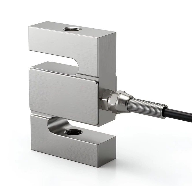
WST401
- Rated load 0.05 to 200 kN — about 5 kg to 20 tonnes
- Comprehensive error ±0.02 to 0.05 %F.S, rated output 2.0 mV/V
- Zero balance ±1.0 %F.S, creep ±0.02 %F.S/30 min
- Safe overload 150 %F.S, ultimate overload 200 %F.S
- Input 380 ± 10 Ω, output 350 ± 3 Ω, insulation above 5000 MΩ
- IP65; 3 m of cable below 5 t, 6 m at 5 t and above
- Operating range −20 to +65 °C
The high-capacity route, and the natural choice when the weighbridge hangs from rods rather than sitting on pads, or when a single cell has to carry a suspended hopper feeding the conveyor. Works in tension or compression, which is why it appears on hopper scales and test benches as well. It is IP65 and the page leads with fitness equipment, so check the environmental class against your site before assuming it suits an outdoor minerals installation — and note that the output tolerance is not stated, which for a two-cell bridge is the number that matters.
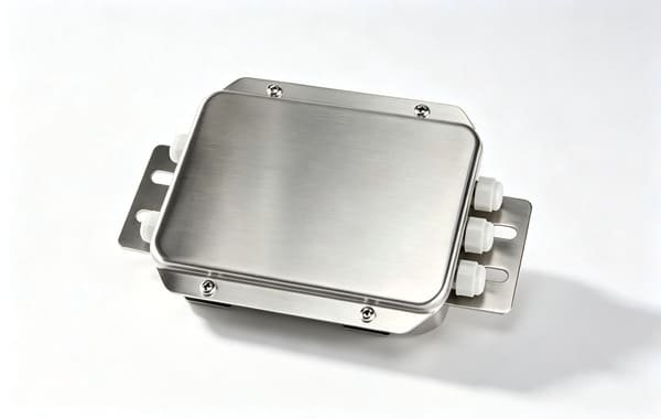
WST1513
- 185 × 134 × 35 mm, stainless steel shell
- Four, six or eight channels
- Precision trim potentiometers for low drift between cells
- Anti-surge and anti-inductive protection on the board, for lightning and switching transients
- Sealed cable glands
This is the part that makes a two-cell bridge into one instrument, and the part that survives a conveyor in a storm. Mount it on the frame near the weighbridge so the cells run on short leads, and use its trimmers for the last tenth of a percent of span match — not for the first percent, and never for the zero. One limit: the page describes its sealing arrangement but does not state an IP rating, so if the box will be hosed or rained on directly, ask us to confirm the number rather than inferring it from “stainless steel”.
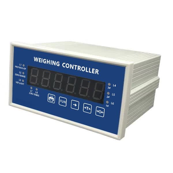
WST1505
- Sigma-delta A/D at 10 or 80 conversions per second, internal resolution 1/1,000,000
- 5 V excitation, drives up to 4 × 350 Ω or 8 × 700 Ω cells
- 6-digit 0.8 inch LED, display resolution 1/3000, selectable division
- 4–20 mA and 0–10 V analogue outputs; 8 relay outputs, 4 opto-isolated inputs
- Isolated RS232/RS485, Modbus RTU, Profibus-DP or Modbus TCP
- Date and time with backup battery; AC 100–240 V
- Operating 0 to 40 °C
A solid process indicator and controller for the weighing layer, with the relay outputs a weigh feeder or a diverter needs. Two limits I will not gloss over. Its operating range starts at 0 °C, while the belt scale rule books work from −10 °C — so on an unheated outdoor installation in a cold climate, this instrument is the wrong choice and the WST1508 transmitter at −10 to +40 °C is the better one. And the specification lists no speed or travel input, which means it cannot compute mass flow on its own; weight times speed and the running total belong to the belt scale integrator or the PLC. Note too that the page gives two different sizes in two places, 158 × 82 × 142 mm in the features and 160 × 83 × 146 mm in the specification table.
And the honest gap, which is the same one as always on a belt scale: bridges above about a tonne per cell. None of the five reaches there except the S-type on a suspended frame, and on a compression weighbridge over a tonne you should be looking at our WST302 shear beam, which runs from 0.05 to 20 tonnes with 150 percent safe overload and a comprehensive error of 0.03 %F.S. I have kept it out of the cards because its page also omits an IP rating and a compensated temperature range, and I would rather you saw those gaps in prose than found them after drawing the frame. Tell me the belt width, the speed and the dead load, and the capacity question answers itself.
16. Seven answers I need before I can size anything
Every belt scale enquiry that ended badly for somebody ended at one of these seven questions, and not one of them is about a sensor. I do not need exact numbers — I need the shape of the machine. Send these and my reply stops being a price list and becomes a design. It is also the list I would give anyone comparing load cells for belt scales, precisely because none of the seven is about a sensor.
| Question | What it decides | What I need from you |
|---|---|---|
| 1. What is the belt doing? | The kilograms per metre, which is the only signal the cell ever sees | Design t/h, belt speed, belt width, and the normal flow range |
| 2. What is the dead load? | Cell capacity, and through it the entire zero budget | Belt weight per metre, idler weights, weighbridge deck weight |
| 3. How many idlers can sit on the bridge? | Weigh length, live load, and whether the frame needs one cell or two | Idler spacing and trough angle, and the number of weigh idlers |
| 4. Who reads the number? | Whether you need certification at all, and which class is worth paying for | Custody transfer, royalty, internal accounting, or process control only |
| 5. Where does the material arrive? | Impact loading, cell overload margin, and whether the bed has settled | Distance from the loading point, and how it is fed: truck, chute, crusher |
| 6. What is the weather doing there? | IP rating, temperature range, wind shelter, and the ambient swing per shift | Covered or open, indoor or outdoor, washdown, winter minimum, coastal air |
| 7. How far away is the cabinet? | Four-wire against six-wire, and whether the signal has to become a current loop | Cable run in metres, the bus your PLC speaks, and whether you can mount a box on the frame |
17. Questions from conveyor builders and plant engineers
Which load cell should I use for a belt scale?
Size it from the belt, not the throughput. Work out the kilograms per metre from Q divided by 3.6 v, multiply by the weigh length to get the live load, add the belt, idlers and deck to get the dead load, and choose the smallest cell that carries that total with somewhere between a quarter and two fifths of its capacity in reserve. Then check the zero budget, because that is what will actually limit you: a pair of 1,000 kg cells on a 1,200 t/h conveyor gets about one degree Celsius of ambient change per quarter of an hour before the fifteen-minute zero test is exhausted. That is what I mean when I say load cells for belt scales are chosen from the belt rather than from the accuracy class.
What accuracy class can I realistically achieve on a belt scale?
On a well-built conveyor with scale-quality idlers, a good weigh frame and a proper material test, class 0.5 is achievable and class 1 is comfortable. Class 0.2 is achievable on the best installations, which is why China legislated it, but it depends far more on the conveyor than on the sensor. What determines the outcome in my experience is alignment, the loading point distance, wind shelter and the maintenance rhythm — not the cell grade. An uncertified machine reading 0.15 percent today with nobody re-zeroing it will be worse in service than a modest class 1 machine that gets a daily zero and a quarterly material test.
Why is my belt scale reading high, or drifting over the shift?
Almost always one of five things, in this order. Material carryback sticking to the belt and idlers, so the tare grows all shift — check the scrapers before you check anything electrical. Ambient temperature, because the legal zero budget is worth about one degree per fifteen minutes. A belt whose stiffness changes as it warms, which is why the manuals ask for twenty to thirty minutes of empty running before zeroing. Wind on an uncovered scale area, which produces lift rather than weight and does not average out. And the pair of cells, if their zeros are not matched. Note that you cannot find this by looking at the totalizer: by the time the drift is visible in the numbers it has already been invoiced. It is rarely the sensor, and load cells for belt scales are replaced far more often than they are diagnosed.
Do the two load cells on my weighbridge have to be matched?
Yes, and this is the most under-specified requirement on the whole machine. The instrument is calibrated on a centred load, so the two cells’ outputs get averaged into one scale factor. When the belt tracks to one side or the loading is asymmetric, the load splits unevenly and the difference between the two cells stops cancelling. The error is half the load imbalance times the output mismatch, so a pair matched to one percent with a twenty percent imbalance costs you 0.10 percent — forty percent of the class 0.5 verification tolerance — and two cells from opposite ends of a ±7.5 percent output band cost 0.75 percent. Ask for matched pairs and ask for the zero differential on the certificate. The junction box trimmers can fix the span; they cannot fix the zero.
Chain code or material test — which calibration do I need?
Both, for different purposes. A chain code or hanging weights verify that the bridge responds correctly and that the electrical chain works, and they are the practical way to check repeatability and the shape of the response without stopping production. A material test against an independent reference is the only method that establishes trueness, and it is what the rule books require for verification. The two are not interchangeable: one published comparison found them stable within about three percent of each other, which is twelve times the tolerance a class 0.5 machine is allowed. Run the chain monthly for repeatability and the material quarterly for truth, weekly if you own a reference facility.
Can I use a belt scale as a weigh feeder too?
The weighbridge hardware is the same, the requirements are not. A totalising scale has to be true over a shift against a reference, so its enemy is zero drift and its timescale is hours. A weigh feeder has to hold a target flow, so its enemy is loop response and its timescale is seconds — and the feedback that trims it comes from the totaliser or the PLC, not from the load cell. A machine can be excellent at one and poor at the other, and the control loop is firmware and drive tuning that I do not supply. I provide the cells, the summing box and the weighing instrument; the feeder controller and its tuning belong to whoever builds the feeder. That is the honest scope of load cells for belt scales and belt feeders alike.
Why can my belt scale not weigh small flows accurately?
Because two independent limits both bite in the same place. Below about twenty percent of rated capacity the instrument is outside the range the rule books describe, and the lawful minimum totalised load of 800 scale intervals starts to take minutes rather than seconds to accumulate. Meanwhile the physics works against you: the signal is proportional to the flow, but the cell’s zero drift is proportional to its capacity, and the capacity is set by the belt’s dead weight, which you already own. At 1.5 tonnes per hour on a single idler the live load is about 0.4 kilograms and the zero drift is fifty percent of it per ten degrees. No cell fixes that. The answer is a loss-in-weight hopper, where the weighing element sees tens of kilograms instead of hundreds of grams.
Can you supply the complete belt scale, or just the load cell?
The weighing layer only, and I would rather be exact about where the line is. I supply load cells, force sensors, junction boxes, weighing indicators and transmitters, matched pairs when asked, and the arithmetic and mounting advice that goes with them. I do not supply the weigh frame, the conveyor, the scale-quality idlers, the speed sensor, the totalising integrator, the wind shelter or the material test facility, I cannot approve or verify your belt weigher, and I supply nothing that performs a safety-rated function. What you get is a weighing solution with the boundary written down, and a supplier whose only interest in your idler alignment is that it stops you buying load cells for belt scales you do not need.
Belt width, belt speed, design tonnes per hour, idler spacing and trough angle, the number of weigh idlers, the belt weight per metre, and the cable run to your cabinet. I will come back with the kilograms per metre, the live and dead load, a cell capacity with the utilisation, the zero budget in degrees Celsius per quarter of an hour, the four-wire or six-wire decision, and a written note on which parts of your error are not mine. If a better load cell is not your limiting factor, that will be the first line of my reply.
VektorForce · load cells, force sensors, junction boxes and weighing indicators · www.vektorforce.com · Robin@vektorforce.com


