
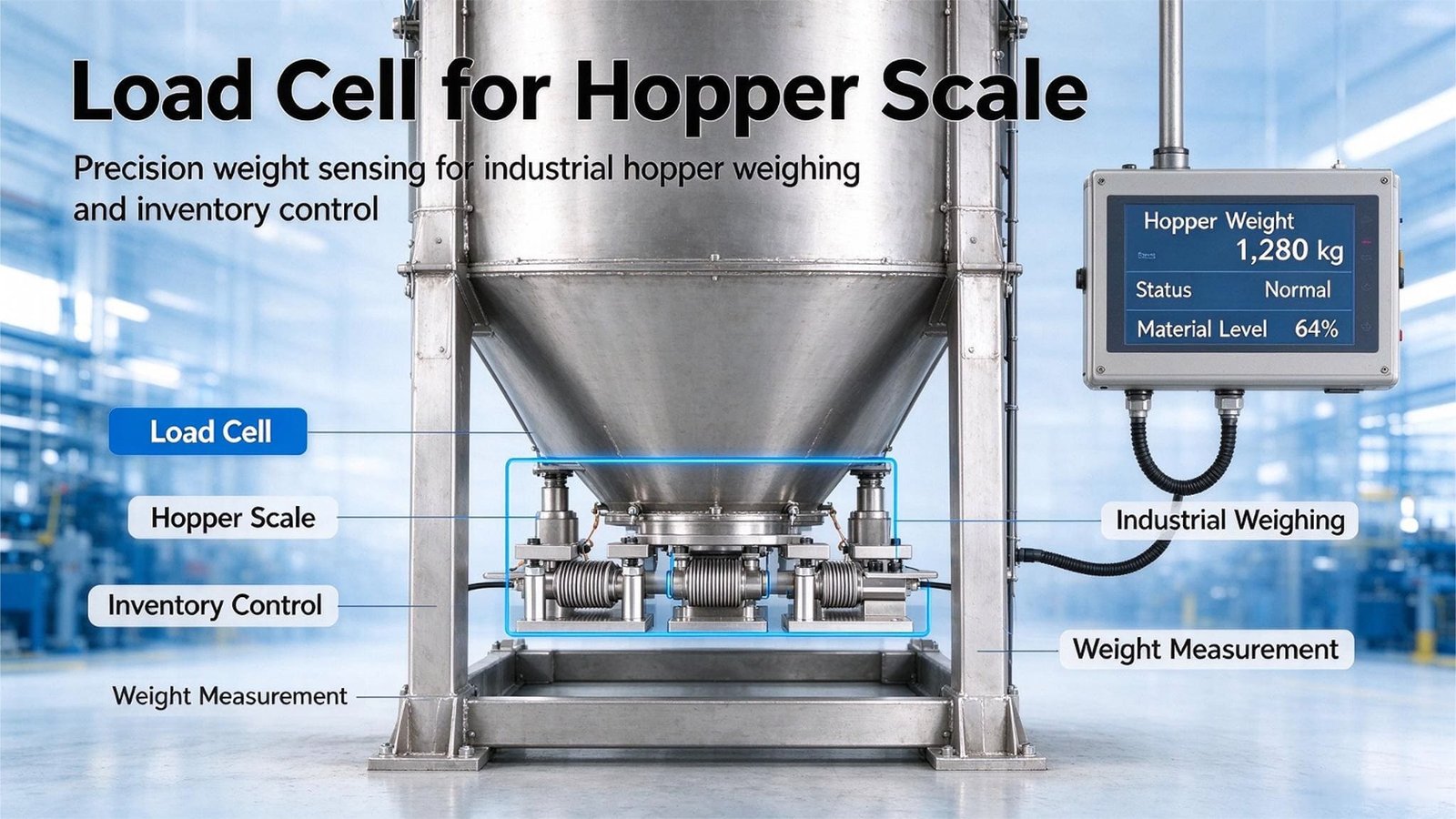
Load Cells for Hopper Scales: Field Notes From the Three Weighing Jobs on a Process Vessel
A hopper scale is not a floor scale with legs. It is a vessel whose weight you interrogate forty times an hour — and where the vessel, not the sensor, usually decides whether the number is any good. Here is the capacity arithmetic, the 0.5% system rule, three projects I worked through, and the honest limits of what a component supplier can promise.
8 October 2026
15 min read
By Robin, export sales engineer at VektorForce. I sell load cells, weighing modules, junction boxes and indicators to the companies that build and run hopper scales — not the vessels, the feeders or the batching software. Everything below comes from projects I have quoted, shipped or troubleshot. Numbers are rounded where it doesn’t change the conclusion.
A hopper scale is a process scale, not a storage scale
Ask most people what a hopper scale does and they will say “it tells you how much material is in the hopper.” That is the storage answer, and it is the answer our own tank and silo guide is written for — the question there is “how much do I have left”, asked once a day or once a shift, where absolute accuracy and long-term zero stability are what matter. You can read that guide here, and the retrofit version of it on a 200-tonne cement silo here.
A hopper scale on a production line is asked a different question. It is asked “how much did I just dose?” — forty, sixty, a hundred and twenty times an hour, and the answer has to be repeatable to a tolerance the recipe sets, not to a tolerance the datasheet sets. That single change of question inverts almost every design decision. For inventory you want a big number that is right once a shift. For dosing you want a small number that is right every forty seconds. Those are not the same instrument, even when they are literally the same vessel.
The market has quietly become enormous, because almost every batch process in the world now closes its loop on a load cell. HTF Market Intelligence sizes the global hopper scales market at US$2.1 billion in 2026, heading to US$4.2 billion by 2033 at an 8.7% CAGR, with Europe the largest region today and Asia-Pacific the fastest growing. PW Consulting puts the narrower weigh-hopper segment at US$945.5 million in 2025 rising to US$1.32 billion by 2032 (4.85% CAGR) — and inside that, loss-in-weight hoppers already take 44.5% of the segment, which tells you how much of the world has moved from “weigh a batch” to “weigh what is leaving, continuously”. The wider automatic weighing and batching systems market is US$3.95 billion in 2026 going to US$5.93 billion by 2032 at 7.0%, with typical dosing accuracies of ±0.1–0.5%, two to twenty ingredient channels, and batches from 5 kg to 5,000 kg.
Who this article is for
If you build batching lines, dosing systems or process vessels and you buy sensors as components, this is a sizing guide written from the supplier side — with the arithmetic that decides capacity, and the mechanical issues that decide whether you ever see the datasheet accuracy in the field. If you run a plant and your hopper scale “drifts” or “doesn’t repeat”, this will help you find out which of the two is actually happening before you buy anything.
The three jobs — dose, meter, monitor — and why they need different cells
Almost every hopper-scale problem I get asked about starts with a customer trying to make one vessel do all three of the following jobs with one set of load cells. They impose three different error budgets, and the budgets conflict.
Job 1 — Dose. Fill the vessel to a setpoint, verify, discharge, repeat. Somewhere between 20 and 120 cycles an hour. The reading only has to be right once, at the instant the feeder cuts off — after that it is history. So the spec that matters is repeatability, and secondarily settling time. Absolute accuracy matters much less, because a small constant offset is calibrated out; scatter is not.
Job 2 — Meter. Loss-in-weight feeding: the vessel empties through a screw or a rotary valve, and the controller differentiates the weight signal to get mass flow in kg/h and controls the feeder on that. This is the fastest-growing use case (44.5% of the weigh-hopper segment) and it is the most demanding on the electronics, for a reason that has nothing to do with accuracy: differentiating amplifies noise, and the faster you want the flow response, the more of it you amplify. The cell here must be quiet, and the A/D must be quiet at a bandwidth you can actually filter.
Job 3 — Monitor. Report what is in the vessel for inventory, for a low-level alarm, or for a leak/bridging check. Slow, absolute, long-term stable. This is the silo/tank case, and it is the one where you can afford to spend capacity for safety.
One sentence per job
Dose: choose for repeatability and settling, and size the vessel small. Meter: choose for low noise and put the resolution in the electronics, not the vessel. Monitor: choose for absolute stability and temperature compensation, and buy the safety factor you want. One vessel doing all three will be mediocre at two of them.
Capacity arithmetic: why K = 1.5 lands you at 67% of full scale
The capacity formula is short and everybody knows it, but few people know where the constant comes from:
Ccell = K × (Wtare + Wmaterial) ÷ N where N is the number of support points and K is the safety factor
K = 1.5 is the standard for a static vessel, and it is not arbitrary — it is chosen so that the dead load plus live load lands inside the 60–75% of rated capacity band that the industry considers the sweet spot for signal quality and overload headroom. Because 1 ÷ 1.5 = 0.667, K = 1.5 puts you at 67% of full scale. That is the whole reason for the number.
A worked example. A three-leg hopper: the vessel, agitator, gearbox, insulation and piping weigh 800 kg empty, and it holds a maximum of 1,200 kg of material. Gross = 2,000 kg, N = 3.
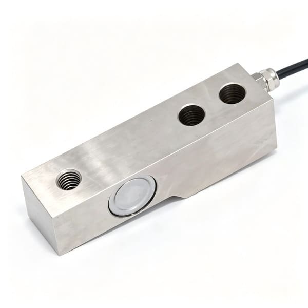
Ccell = 1.5 × 2,000 ÷ 3 = 1,000 kg per leg — so three 1-tonne cells. In our range that is either a WST302 shear-beam cell (0.05–20 t) on a machined mount, or a WST303 bellows-type bending-beam cell (0.1–10 kN, stainless, sealed), depending on how much side load and how much washdown the mounting has to survive.
When K must become 2.0. There are four honest reasons to double the safety factor: material dropped from height onto the vessel (a bulk bag or a front-loader bucket), an agitator whose drive is mounted on the weighed frame, an outdoor vessel exposed to wind, or a seismic region. K = 2.0 drops your working point to 50% of full scale, and — this is the part people miss — every error in the datasheet is expressed in %FS, so dropping the working point by a third makes every error larger in grams by the same factor. You paid for safety with accuracy. Sometimes that is the right trade; just make it knowingly.
The tare number is always wrong the first time
The tare I am quoted in a first email is usually 1.5 to 2 times smaller than the tare I eventually find. Nobody remembers the agitator gearbox, the insulation and cladding, the steam tracing, the pneumatic vibrators, the operator platform someone bolted on in year two, or the 2.5 metres of pipe that will sit on the nozzle. Ask for the vessel to be weighed or modelled, not estimated — a hopper sized on an estimated tare has no overload headroom left and no accuracy left either. If the real gross turns out to be 2,900 kg instead of 2,000 kg on that three-leg vessel, you are not at 67% of full scale, you are at 97%, and the next shock event takes the cells out.
The live-load window: %FS is measured on the wrong number
Here is the fact that decides more hopper-scale outcomes than any other, and it follows directly from the tare problem above.
Every error figure on a load-cell datasheet is a percentage of full scale. But on a hopper scale, the part of the range that carries your process information is only the live load — the material. If the tare is four times the dose, your entire measurement lives in the top slice of the range, and the cell’s error terms are spent on the tare, not on the dose.
Take a 2,000 kg shear-beam cell (WST302, comprehensive error 0.03% FS, zero temperature effect ±0.02% FS per 10 °C). Put it under a vessel with a 1,600 kg tare and watch what the same temperature swing does to three different dose sizes:
| Dose (live load) | Live window as %FS | Zero drift ±0.02%FS/10 °C, in grams | As % of the dose |
|---|---|---|---|
| 400 kg | 20% | 400 g | 0.10% |
| 40 kg | 2% | 400 g | 1.0% |
| 4 kg | 0.2% | 400 g | 10.0% |
Same cell. Same datasheet. Same building. The error on the dose moves by a factor of a hundred, purely because of how much material the customer puts in the vessel. This is why I ask for the dose size before I ask for anything else. If someone tells me they want to dose 4 kg on a two-tonne vessel, my answer is not a different cell — it is a different vessel.
Creep behaves the same way, and the cycle time is what decides it. The specification is ±0.02% FS per 30 minutes, which on this 2,000 kg cell is 400 g. If the batch is held for 40 seconds, even assuming the worst case (that creep accumulates linearly, which it does not — real creep is logarithmic with most of it happening early), you have accumulated 400 × (40 ÷ 1,800) ≈ 9 g. If the same vessel is instead held for twenty minutes while an operator waits for a lab result, the same spec gives 267 g. Identical cell, identical specification, and the creep contribution differs by a factor of thirty depending on what the process does with the vessel. A datasheet cannot tell you whether creep matters. Only your cycle time can.
The rule that saves the most money
%FS is a property of the load cell. Grams is a property of the vessel. Before comparing one cell’s 0.03% against another’s 0.02%, work out what the live load is as a fraction of full scale. If the answer is under 10%, you are not choosing between two cells — you are choosing between two vessels, and the cell spec is a rounding error either way.
The 0.5% system rule: 96% of your error is mechanical, not electrical
This is the section I would keep if I could only keep one.
Our own installation training carries a number I have never seen published anywhere else, and it is worth more than most datasheets. For a group scale of five-tonne cells on eight legs — a 40-tonne total system — the achievable total weighing error is 0.5%, that is 200 kg, and that is the figure you get when installation and calibration are both done correctly.
Now decompose that 200 kg. Our WST302 has a comprehensive error of 0.03% FS, so on a 5,000 kg cell each cell contributes 1.5 kg. Add up eight of them:
- Worst case, all eight errors the same sign and adding directly: 8 × 1.5 = 12 kg.
- Random, uncorrelated, adding as √N: √8 × 1.5 ≈ 4.2 kg.
So the entire electrical chain — cells, junction box summing, cable, indicator — contributes somewhere between 4 and 12 kg of a 200 kg budget. That means 94% to 98% of the total error is mechanical. Off-level mounting pads, piping that binds, thermal expansion of a 20-metre steel structure, wind on a tall vessel, side force from an unbalanced load, legs that don’t share the load equally.
The purchasing consequence is uncomfortable but useful. Upgrading from a 0.03% FS cell to a 0.02% FS cell improves your system error by roughly 0.05 kg out of 200 kg. It is invisible. The same money spent on flexible pipe compensators, a machinist’s level and coplanar shims, and a proper corner adjustment changes the number by tens of kilograms. If a supplier sells you a more accurate cell to fix an accuracy problem on an installed hopper scale, ask them what the mechanical error budget is first.
The second consequence is the one that changes the architecture of a whole plant, and it comes straight out of the same rule: the system error scales with the total vessel capacity, not with the dose. 0.5% of 40 tonnes is 200 kg whether you are dosing 5 kg into it or 5,000 kg. So:
| Vessel gross capacity | 0.5% system error | As % of a 25 kg dose | Verdict |
|---|---|---|---|
| 20 t | 100 kg | 400% | Impossible |
| 5 t | 25 kg | 100% | Impossible |
| 500 kg | 2.5 kg | 10% | Workable with care |
| 150 kg | 0.75 kg | 3% | Comfortable |
Read that table again with a real plant in mind. A 20-tonne bulk hopper can never dose 25 kg, no matter how good the load cells are, no matter which indicator you buy, no matter how carefully it is calibrated. The error budget of the vessel is a hundred kilograms. And the fix is not electrical — it is architectural: put the recipe on the smallest vessel that can hold the dose, and let the big hopper only report inventory. That is the whole of Case 1 below.
Case 1: a premix plant in Konya and the 25 kg dose no bulk hopper can hold
November 2025. A feed premix plant near Konya, Turkey, building their own batching line. The enquiry was short: “we want to add a micro-ingredient at 25 kg per 500 kg batch, and we want to do it on the existing bulk hopper so we don’t have to buy a second vessel. What load cells do we need?”
Before answering I asked for the tare, weighed. The customer had estimated 2 tonnes gross. The real figure: vessel 620 kg, agitator and gearbox 180 kg, insulation and cladding 40 kg, and an operator platform bolted on in year two at 90 kg — a tare of 930 kg, plus 1,200 kg of material, so 2,130 kg gross. They had sized four WST302 cells at 3 tonnes each — 12 tonnes of installed capacity for a 2.13-tonne vessel, because “bigger is safer”. Their working point was 17.8% of full scale.
Now put the two problems side by side.
Problem one: the increment is smaller than the error floor. Adding 25 kg to a vessel reading 2,130 kg means detecting a change of 25 ÷ 2,130 = 1.17% of the reading. The system error, per the 0.5% rule from the section above, is 0.5% × 12,000 kg = 60 kg. The 25 kg increment is 0.42 times the error floor — the signal is buried. And even ignoring the mechanical error entirely, the cells alone give 4 × 0.03% × 3,000 = 3.6 kg of comprehensive error, plus a zero temperature effect of 0.02% × 3,000 = 600 g per cell = 2.4 kg across four legs. Call it 4.3 kg of pure electrical error on a 25 kg increment: 17%. For a premix where the whole point is formulation accuracy, that is unusable — and no change of cell model fixes it, because the vessel is the problem, not the cell.
Problem two, and the worse one: you cannot weigh an increment by difference on a vessel whose contents are moving. Every time that agitator ran, the reading moved by tens of kilograms. The customer’s own operators had learned to read the display “when the mixer is off”, which is a diagnosis, not a workaround.
So I quoted two things, and told them the first quote was the one that mattered.
- Keep the bulk hopper exactly as it is for what it is actually good at: inventory and low-level alarms. Four WST302 cells at 3 tonnes each is a perfectly sound storage scale on a 2.13-tonne vessel — 17.8% working point is not a fault in a monitor, and the 60 kg error is irrelevant when the question is “do I have 1.2 tonnes or 0.2 tonnes left”. They changed nothing there.
- Add a separate 150 kg micro weigh hopper on three WST804 bellows-type weighing modules rated 100 kg each, discharging into the main line by screw.
The arithmetic on the second option: total system capacity 3 × 100 = 300 kg, so the conservative 0.5% system error is 1.5 kg — 6% of a 25 kg dose as an upper bound. In practice, with coplanar pads and a proper calibration, their measured static accuracy was 0.35 kg, or 1.4% of the dose. Add a two-speed feed with a learned preact, and the cycle-to-cycle repeatability we measured alongside them settled at ±0.06 kg, or 0.24%. From 400% to 0.24%, by changing the vessel instead of the cell.
One thing went wrong, and it is worth repeating because it recurred in two later projects. The first mounting put the micro hopper’s discharge screw motor on the weighed frame. Every time the screw ran, its reaction torque moved the reading by 1.1 kg — 4.4% of the dose, from a motor nobody had thought of as a weighing component. Moving the screw motor onto a separate bracket, coupled by a flexible shaft, cost one afternoon and removed the whole error. If there is a single sentence this article exists to deliver, it is that one: anything that applies force or torque to a weighed vessel is part of the weighing system, whether or not it is bolted to the load cells.
In-flight material: the valve is the bottleneck, not the sensor
Every gravimetric filler has the same architecture, because it has to. A two-speed feed runs the feeder at full rate to roughly 90% of setpoint, drops to a dribble at 5–15% of the flow rate up to about 98.5%, and then the controller commands a cutoff. The material already falling or in flight at that instant is the preact — the落差 — and the controller learns it per ingredient and subtracts it from the next cutoff point.
The instinct of every automation engineer who has ever chased a batching problem is that a faster sensor will tighten the preact. It won’t, and here is why.
Our WST1502 indicator converts at 10, 20 or 80 times a second. At 80 sps, a fresh, settled weight is available every 12.5 milliseconds. A pneumatic butterfly valve or a pinch valve takes 200 to 1,000 milliseconds to close, and product keeps flowing for the whole of that time. The sensor chain is 16 to 80 times faster than the actuator it is commanding. Buying a 400 Hz converter to improve batching repeatability is like buying a faster stopwatch to make the train arrive on time.
This is the exact opposite of the advice I gave in our notes on agricultural crop-protection drones, where a 10 sps default in a tank-weighing indicator was the bottleneck and caused a phantom 0.4 litres of residual chemical. Same supplier, same 10/80 sps indicator family, opposite recommendation — because the physics of the two applications are opposite. In dosing, the material has to be stopped and stopping takes hundreds of milliseconds. In a spray tank, the material has to be measured while a helicopter rotor is shaking it at 150 Hz. Always ask which side of the loop the delay is on before buying speed.
Where the sensor does matter for preact is quieter than “speed”, and more important. The preact the controller learns is read from the load cell at the instant of cutoff. If the reading carries 200 g of short-term noise on a 25 kg dose, then the learned preact carries that noise, and it never averages out — it becomes a bias in the cutoff point, and it changes with every cycle. The correct requirement for a dosing cell is therefore not “fast” but “quiet at the moment of decision”. Practically that means three things: a working point in the 60–75% of full scale band (best signal-to-noise in counts), a stable low-noise excitation and converter, and a moving-average filter of 5 to 20 samples applied to the steady portion of the fill only — never across the fill itself, or you delay the cutoff.
The resolution arithmetic, so you can stop worrying about it. The WST1502 has an A/D resolution of 5,000,000 counts across a ±10 mV input. With 5 V excitation and a 2.0 mV/V cell, full scale output is exactly 10 mV, so full scale is 5,000,000 counts. On a 1,000 kg cell that is 5,000 counts per gram, and a 25 kg dose occupies 125,000 counts. A few counts of noise is a fraction of a gram. Resolution is never the limiting factor on a hopper scale — the mechanical ring-down of the vessel and the impact of the falling material are. The same conclusion I keep arriving at on every dynamic weighing project I have worked on.
The legal floor nobody checks: minimum capacity
If the weights you dose have legal or contractual standing, OIML R76 sets a minimum capacity Min = 20 e for a class III instrument, where e is the verification scale interval. On a system with e = 500 g, Min = 10 kg — so a 25 kg dose is only 2.5 Min, which is thin, and a 5 kg dose is below the legal floor altogether; you would need e ≤ 250 g to weigh it. Ask the question before you design the vessel, because the answer determines the division size the indicator must offer. Our WST1505 process indicator and WST1502 both offer division ranges from 1 to 500, so the division is rarely the constraint — but the vessel’s error floor usually is.
Five installation sins and the adjustment nobody does
The 0.5% system rule told us that 94–98% of a hopper scale’s error is mechanical. These are the five mechanical failures I see most often, in the order they cost the most money.
1. Mounting pads that are not coplanar. All load-cell mounting surfaces must be level and on the same plane. A leg sitting two millimetres proud takes a different share of the load — which means one cell works harder at peak fill, another never reaches a useful part of its range, and the summed reading changes when the fill pattern changes. The fix costs nothing but happens before installation: put a machinist’s level across all pads and shim as needed, before you torque anything down.
2. Rigid process piping. The inlet and outlet connections are the most underestimated error source in the whole system. A rigid DN80 pipe bolted to the vessel nozzle does not just “hold up” some of the weight — it also transmits the thermal expansion of the whole pipe run, and if the line is pressurised or pneumatically conveying, the reaction force rides directly on your load cells. The fix is a flexible bellows compensator immediately adjacent to the nozzle, oriented so that its own stiffness is load-neutral in the vertical direction, and independently supported so its mass doesn’t hang on the vessel either. Every kilogram of pipe that reaches the cells is a kilogram of error that no calibration can remove.
3. Thermal expansion with nowhere to go. A 20-metre steel structure grows roughly 4 to 5 mm across a 40 °C annual swing. If the mounting cannot accommodate horizontal movement, that growth converts into a vertical force through the mounting geometry, and what you see in the plant is a daily zero drift that correlates with the ambient temperature — worst in the morning after a cold night. This is why weighing modules exist as a product category: a good module allows controlled horizontal movement (our WST803 and WST804 both use a self-aligning ball-and-plate interface with an anti-eccentric-load feature) while restraining side force and uplift. Pair it with a sensible zero-tracking window in the indicator and the drift mostly disappears.
4. Welding near a mounted cell, without grounding. If anybody strikes an arc on the vessel or its frame after the cells are wired, the welding current will find the cell’s strain-gauge leads as a path to earth, and it does not take much to destroy a foil gauge. The rule is simple and old: load cells are the last thing you install, and if you must weld afterwards, clamp the welding return directly to the workpiece and disconnect the cells before you start.
5. Shear-beam cells installed the wrong way up. This one comes straight out of our own after-sales file. A shear-beam cell has an arrow on the body, a fixed end and a free end. Installed upside down, the beam bends the wrong way and the signal goes negative; the customer’s first instinct is always “the cell is broken”, and the second is to swap the signal wires. The fixed end must be bolted rigidly to the frame, the free end must carry the load with a gap to the frame so it can actually deflect, and in a group scale every cell’s arrow must point up. The same file notes that the mounting plate the cell bolts to must be thick enough to be genuinely rigid — a flexing mounting plate is an uncontrolled spring in your weighing system.
The adjustment nobody does: corner trim
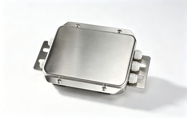
In a multi-cell group, every cell has a slightly different sensitivity, so every leg contributes a slightly different signal for the same force. The check is mechanical and takes twenty minutes: load each leg in turn with the same test mass and record the reading. Suppose you get 235 / 248 / 230 / 256 kg. The minimum is 230 — so you trim the other three down to 230 using the potentiometers in the junction box, then recalibrate. The critical detail is that a trim potentiometer is a one-way attenuator: it can only reduce a channel, never increase it, so you always trim toward the lowest cell, and you never “adjust up” to match the highest. Our WST1513 stainless junction box carries high-precision low-drift trimmers on four, six or eight channels for exactly this job. On a floor scale nobody bothers, because the load’s centre barely moves. On a hopper the centre of mass travels as the vessel fills and as the agitator swings — which is why corner error matters far more here, and why Case 2 below existed.
Case 2: Czechia and the 3 kg drift that was a pipe
February 2026. A chemical powder plant in Czechia, three-leg five-tonne stainless feed hopper on a mezzanine, feeding a reactor. Two complaints arrived together: the zero drifted by ±3 kg overnight, and the operators “didn’t trust” the reading because it changed every time a forklift went past in the aisle below.
I asked for photographs of both ends of the vessel, and for a corner test. The photographs and the numbers told the story between them.
- The outlet screw feeder was bolted rigidly to the hopper cone, and beyond it ran 2.5 metres of rigid DN100 pipe to the reactor. That pipe run’s own thermal growth — a warm plant in winter, cold at night — was pushing up on the cone, and the cone was transferring the force straight into the cells.
- The three legs stood on a mezzanine steel deck, not on a foundation. Forklift traffic deflected the deck, and the deck carried the load cells.
- The corner test showed one leg reading +11% relative to the others. It had been like that since commissioning eighteen months earlier and nobody had noticed, because everybody only ever looked at the total.
The fixes, in the order I made them do it, with the drift measured after each step:
- Cut the rigid pipe and fit a flexible bellows compensator at the vessel nozzle, independently supported so its mass doesn’t hang on the nozzle. Overnight drift: ±3 kg → ±0.9 kg.
- Re-level and shim the three pads against a machinist’s level, and move the cells onto a stiffened sub-frame that does not take the forklift deflection. Drift: ±0.9 kg → ±0.4 kg.
- Corner adjustment on the WST1513 junction box, trimming the high leg down. The “reading changes when the fill level changes” complaint disappeared with it.
The lesson I want to leave here is the one about the +11% leg, because it generalises. A per-leg sensitivity error is a systematic error that scales with that leg’s share of the load. As long as the load distribution stayed the same, it simply looked like a small scale-factor error on the whole system and was absorbed by the calibration constant — which is why it survived eighteen months of looking “fine”. The moment the fill pattern changed, the same error started to look like noise. A calibration cannot fix a corner error. Only a corner adjustment can. If your hopper scale reads differently at half-full than at full, in a way that repeats, test the corners before you buy anything.
Agitators: the torque that arrives as a vertical force
If the vessel has an agitator or a mixer, and the drive motor is mounted on the weighed vessel, then the motor’s reaction torque is carried by your load cells. This is the single most common cause of “the reading oscillates while mixing” that has nothing to do with the sensor.
Here is the arithmetic, and it is worth doing before the machine is built. A pure torque M applied to a vessel supported on several points is reacted as a pair of opposed vertical forces separated by the characteristic width w of the support pattern. The differential leg force is approximately:
F ≈ M ÷ w and M = P ÷ ω where P is shaft power in watts and ω is angular velocity in rad/s
A real project: September 2025, a food ingredient blender in the Valencia region of Spain. A 1,500 litre paddle blender on four WST302 cells, 250 kg batches, driven by a 2.2 kW gearmotor at 32 rpm. The complaint was that the display swung ±8 kg during mixing and their PLC aborted the batch on a deviation alarm. Their proposed solution was to buy a faster indicator.
The torque first: ω = 2π × 32 ÷ 60 = 3.35 rad/s, so M = 2,200 ÷ 3.35 = 657 N·m. Their support pattern was a rectangle roughly 1.0 m wide, so the differential leg force was F ≈ 657 ÷ 1.0 = 657 N, which is 67 kg. Their observed sum swing was ±8 kg — about 12% of that differential.
And here is the part that ties this section to the corner-trim box above. A pure couple cancels in the sum: if one leg gains 33 kg and the opposite leg loses 33 kg, the total is unchanged. What does not cancel is the portion where the legs do not respond identically. A 12% corner error on a 67 kg differential leaves 8 kg in the sum — and the plant’s corner test had shown exactly that class of error. The oscillation was not noise and it was not sampling. It was a real torque, revealed by a mechanical imperfection.
Which is why no filter can fix it. A filter cannot distinguish 67 kg of genuine vertical force from 67 kg of material, because as far as the load cell is concerned they are the same thing. The force appears at the agitator’s rotational frequency — 0.53 Hz here, plus a blade harmonic at 1.07 Hz — and averaging over a longer window only helps if the force averages to zero over that window, which requires the agitator to be perfectly balanced, which it never is.
The fixes, in descending order of effect:
- Take the drive off the weighed vessel. Mount the gearmotor on a separate pedestal and connect it with a flexible coupling or a longer shaft. This removes the entire error at source, and on this project it took the swing from ±8 kg to ±1.2 kg. We had already done exactly this to a screw motor in Case 1; it is the same fix in a bigger frame.
- React the torque mechanically, not through the cells. A torque arm or a pair of check rods that carry the couple into the fixed structure while still allowing free vertical movement does most of this work. This is also why some process vessels use a “pendulum” or anti-vibration mounting assembly rather than a plain one.
- Weigh before mixing, then lock the reading. If the process allows it, take the weight while the vessel is still, close the measurement window when the agitator starts, and judge the batch on that number. This is a control fix, it is free, and it is step three’s whole content in Case 3.
- Only then filter — and use a moving average of 5 to 20 samples rather than a single-pole low-pass, because a moving average has a computable settling time you can put into your cycle-time budget instead of guessing at it.
After the pedestal move and a corner trim on the junction box down to under 2%, the Spanish blender’s swing during mixing was ±0.3 kg, and the gated reading taken in the two seconds after the agitator stopped was ±0.05 kg. Their deviation alarm now sits at ±1 kg and never fires. Total cost: one pedestal, one flexible coupling, one afternoon, and no new electronics. They had been about to buy an indicator.
Bare cell or weighing module? What the module actually fixes
A weighing module is not a marketing wrapper around a load cell. It is an engineered assembly that integrates the cell, the top plate, the bottom plate, the load-bearing components and the protection limit devices into one unit, so that a vessel can be turned into a scale without the machine builder having to design a weighing mechanism. The value is entirely in the last part of that sentence.
What a module removes is the installation error — which, as we worked out earlier, is 94–98% of your total. Specifically it brings: a self-aligning ball or plate interface that centres the load automatically; an anti-eccentric-load geometry so that a slightly off-centre load does not bend the cell; a horizontal restraint that keeps side force away from the sensing element while still allowing the horizontal movement that thermal expansion demands; and an anti-overturn bolt that resists uplift, doubles as a jack for changing a cell without emptying the vessel, and protects the cell during transport.
| Weighing module | Bare load cell | |
|---|---|---|
| Accuracy | As good as the cell inside it | As good as the cell, if you mount it right |
| Mounting plates and load-bearing parts | Supplied, matched to the cell | You design and machine them |
| Lateral / vertical / anti-overturn protection | Supplied | You design and machine them |
| Centring and eccentric-load behaviour | Automatic | Depends entirely on your design |
| Cell replacement in the field | Bolt out, bolt in, re-trim | Often needs re-machining of the mount |
| Best fit | First-time builders, retrofit, field service | High-volume OEM with their own proven mount |
But be honest about the boundary, because I have to be with my own customers. A weighing module fixes the mechanical error. It does not fix the process error. In Case 1, the module did nothing about the discharge screw motor’s reaction torque — only moving the motor did. In Case 3, no module on earth fixes an agitator whose gearmotor sits on the weighed vessel. Modules are worth their price when the customer’s mechanics are the weak point. They are not a substitute for thinking about every load path onto the vessel.
Two more of our modules, for the two sizes either side
Below the WST804 there is nothing in the catalogue, so if your dose is under about 10 kg you are into a custom build and we should talk about it early. Above the WST803, our WST801 spoke-type module covers 5 to 200 tonnes per leg for heavy silos and large vessels, and for vessels that are suspended rather than stood on legs, the WST402 and the WST504 spoke-type cell cover the middle of the range. If your vessel is an existing one being retrofitted and welding on it is not allowed, there is also a strain-based route — the same approach as our micro strain sensor — which we have used on retrofit silo projects where cutting into the legs was impossible.
Dust, washdown and zones: where our catalogue stops
The environment decides more of the long-term outcome than the accuracy class does, and it is the part of the enquiry people leave out. Four cases, four different answers.
| Environment | Typical products | What the sensor side needs |
|---|---|---|
| Dry indoor, non-caking powders | Premix, masterbatch, dry mortar, mineral filler | Alloy steel cells and IP65 modules are correct. Watch static build-up with plastics — earth the vessel and the cable shield |
| Dusty, and the dust is combustible | Flour, sugar, starch, cocoa, wood pellets, aluminium powder | The vessel interior is often Zone 20 and the surroundings Zone 21/22. Equipment there needs ATEX 2014/34/EU or IECEx certification — typically Ex ia with safety barriers, or Ex ta for dust zones without barriers |
| Washdown / CIP | Dairy, wet pet food, beverage premix, nutraceutical | 304/316L body, IP68 laser-welded hermetic sealing, and a hygienic module with no crevices that trap product |
| Corrosive | Fertiliser, salt, brine, acids, chlorides | 316L body, PTFE or polyurethane cable jacket, and a mounting geometry that does not create a crevice where salt settles |
Now the part I have to say plainly, because it costs me orders and it is still the right thing to say: our catalogue load cells and weighing modules are IP65 and carry no ATEX certification. IP65 survives dust and splashing water. It does not survive a nightly high-pressure wash at 80 °C, and it is not a legal answer in a classified dust zone. If your flour mill, sugar silo or cocoa plant is zoned, or if you wash the vessel down every night, say so in the first email. What you will get from me is either a different construction on the sensor side with appropriate barriers and the honest statement of what is and is not certified, or a straight referral to someone whose product line is built for it. I would rather lose that order than ship a cell that fails in three months and takes your plant’s confidence in weighing with it.
One last practical point that outranks all of it: the most common real failure mode of a load cell is not the electronics, it is the cable entry. A cable entering through a gland that faces upward collects water; a PVC jacket embrittles in a chemical plant; a cable run laid next to a motor drive picks up switching noise. Run the cable in conduit, keep it away from power cables, use the right jacket for the environment, and do not shorten or lengthen a load-cell cable without checking what it does to the output impedance.
What I ask for before quoting a hopper scale
Every good hopper-scale quote I have produced started with the same nine questions. If you can answer all nine, I can usually size the cells and name the mechanical risks in one exchange instead of five.
- Which job? Dose, meter, or monitor — and does one vessel have to do more than one? If the answer is “all three”, we are going to have a conversation about splitting the vessel.
- The tare, weighed or modelled. Vessel, agitator and gearbox, insulation, steam tracing, piping spools, vibrators, and anything bolted on since commissioning. Not an estimate.
- The maximum material load, plus the material’s behaviour: free-flowing, bridging, caking, hygroscopic, dusty, or abrasive. This decides the mounting geometry as much as the capacity.
- The dose and its tolerance, in grams and as a percentage, and how many doses per hour. The tolerance in grams is the number the whole design hangs on.
- Support points and geometry — a three-point triangle or a four-point rectangle, and the characteristic width between them. I need the width for the torque arithmetic in the agitator section above.
- Agitator or mixer — yes or no, and where is the drive mounted? On the weighed frame or on a separate pedestal. This single answer changes the specification more than any datasheet parameter.
- Every pipe connection to the vessel — size, rigidity, pressure, temperature — and what sits at the other end. If any of them is rigid and load-bearing, we need to fix that before we talk about cells.
- The environment: indoor or outdoor, temperature range, washdown frequency and chemistry, and whether any part of the installation is a classified zone.
- The controller side: PLC platform, required interface (4–20 mA, 0–10 V, Modbus RTU, relay setpoints), and your cycle-time budget so we can size the filter and the settling window honestly.
What we supply — and what we don’t
I want to be precise about this, because the most expensive mistakes in this business happen when a component supplier lets a customer believe it is a system supplier.
| What we supply | What we do not supply |
|---|---|
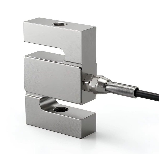
| Load cells: shear beam (WST302, 0.05–20 t), bellows-type bending beam (WST303, 0.1–10 kN, stainless), S-type tension and compression (WST401, 0.05–200 kN), spoke and double-ended types for heavier vessels | The vessel itself — hopper, silo, tank, agitator, feeder, screw, rotary valve, pneumatic system, or any of their mechanical design |
| Weighing modules ready to bolt on: WST803 (0.5–5 t), WST804 (10–500 kg), WST801 (spoke type, 5–200 t per leg) | The PLC, the batching recipe, the preact-learning algorithm, the two-speed feed logic, or any control software |
| Multi-channel stainless junction boxes with high-precision low-drift trim potentiometers: WST1513, four / six / eight channels, with anti-surge protection | CIP or hygienic design of the vessel, and HACCP or food-contact compliance of the machine. Those belong to the machine builder and the plant |
| Indicators and transmitters: WST1502 (RS485, 80 sps, 5,000,000-count A/D), WST1505 (process controller with HI/OK/LO relays), WST1508 and WST1510 (4–20 mA / 0–10 V / Modbus RTU) | ATEX or IECEx certification of a weighing system. We can discuss intrinsically safe construction on the sensor side, but the zoned assembly and its certificate are not ours |
| Engineering on the sensor side: per-leg capacity from your tare and dose, live-window analysis in grams, corner-trim procedure, calibration protocol, module mounting guidance, and matching test data with every order | OIML R76, R61 or R107 instrument approval, legal-for-trade approval, or any statement about the accuracy of your finished scale. Those certificates belong to the complete instrument, assessed on the finished machine |
The standards worth knowing, since they are routinely confused with each other. OIML R60 is the load cell: class C3 means 3,000 verification intervals, and it is a component-level certificate. OIML R76 covers non-automatic weighing instruments. OIML R61 covers automatic gravimetric filling instruments — the batch fillers — graded by a reference accuracy class X(x). OIML R107 covers discontinuous totalizing automatic weighing instruments, which is the formal name for a totalizing hopper weigher, with accuracy classes 0.2, 0.5, 1 and 2 expressed as a percentage of the totalized load. Around those sit the EU Measuring Instruments Directive 2014/32/EU for automatic instruments (Annex MI-006) and Directive 2014/31/EU for non-automatic ones, and in the United States NIST Handbook 44 with its automatic bulk-weighing section and the NTEP certificate of conformance. A useful dividing line: a hopper scale used only for internal process control needs none of these approvals — but the moment its weighment determines payment, the applicable certificate becomes a hard procurement requirement and the whole instrument, not just the cell, has to be type-approved. If that is your situation, tell me, and I will tell you honestly what role we can and cannot play in getting you there.
Five projects where I would rather you did not buy from us
| What you want to do | Why a catalogue strain-gauge solution is the wrong tool | What to do instead |
|---|---|---|
| Dose below about 0.5% of the vessel’s gross capacity | The 0.5% system rule says the vessel’s own error is larger than your dose | Move the dose onto a small weigh hopper with its own cells |
| One hopper scale for both recipe accuracy and inventory | The two jobs need opposite trade-offs in capacity and speed | Two vessels: bulk for inventory, small for the recipe |
| Read and act on the weight while the agitator is running | Torque arrives as a real vertical force that no filter can remove | Move the drive off the weighed frame, and gate the reading |
| Use a hopper scale as a checkweigher | 20–120 cycles an hour cannot compete with 100–300 packs a minute, and each cycle needs the vessel to settle | Use a checkweigher with a short weigh belt |
| Certified ATEX or IP68 washdown from our catalogue | Our catalogue cells and modules are IP65 and unzoned | Tell me at enquiry stage — expect a different construction or a referral |
Frequently asked questions
- 1. How do I calculate the load cell capacity for a hopper scale?
- Use C per cell = K × (tare + maximum material) ÷ number of supports, with K = 1.5 for a static vessel and K = 2.0 if material is dropped from height, the agitator drive is on the weighed frame, or the vessel is outdoors and windy. K = 1.5 deliberately puts the dead-plus-live load at about 67% of rated capacity, inside the 60–75% band where signal quality and overload headroom are both good. Then check the live window: if the material is less than 10% of full scale, the capacity choice dominates your accuracy long before the cell’s error class does.
- 2. What is the difference between a hopper scale and a silo scale?
- Not the hardware — the question being asked. A silo scale answers “how much is in there” for inventory, so it wants absolute accuracy and long-term zero stability. A hopper scale in a process answers “how much did I just dose”, so it wants repeatability and settling speed. If you ask one vessel to answer both questions you will get a compromise that is mediocre at the one you actually care about.
- 3. Can one hopper scale handle both inventory and recipe accuracy?
- Practically, no. The total weighing error of an installed multi-cell group scale is on the order of 0.5% of the total vessel capacity, and that error scales with the vessel, not with the dose. On a 20-tonne hopper that is 100 kg of error — irrelevant for inventory, fatal for a 25 kg dose. The reliable architecture is two vessels: a large bulk hopper that reports inventory, and a small weigh hopper that holds the recipe.
- 4. Why does my hopper scale zero drift overnight?
- Three causes, in order of likelihood. First, rigid process piping: the pipe run’s thermal expansion pushes on the vessel, and the drift then correlates with ambient temperature. Second, the cells are mounted on a structure that moves — a mezzanine deck, a weak platform — which shows up as drift when traffic or machinery runs. Third, the cell’s own zero temperature effect, typically around ±0.02% FS per 10 °C. Fix them in that order; the sensor is usually last.
- 5. Do I need weighing modules, or can I use bare load cells?
- If you build machines in volume and already have a proven mounting design, bare cells are efficient. If you are building a vessel scale for the first time, or you are an end user retrofitting, a module pays for itself by removing the installation error — which is where most of your total error lives. A module supplies the plates, the load-bearing parts, the centring, the lateral and anti-overturn protection and the grounding point, all matched to the cell.
- 6. Why does the weight reading oscillate while the mixer is running?
- Because the agitator’s reaction torque is carried by the load cells. For a vessel on supports of characteristic width w and a shaft power P at angular speed ω, the differential leg force is roughly (P/ω)/w. A 4 kW drive at 48 rpm on a support width of 1.2 m produces a differential of about 66 kg. The oscillation appears at the rotational frequency and its blade harmonics, and it is a genuine vertical force, so no filter can remove it. Move the drive off the weighed frame, react the torque mechanically, or weigh before mixing and lock the reading.
- 7. Is my hopper scale legal for trade?
- It depends what it is for. A hopper scale used only for internal process control needs no metrological approval. The moment its weighment determines payment or a declared quantity, the whole instrument needs type approval: OIML R107 for a totalizing hopper weigher, OIML R61 for an automatic gravimetric filler, or OIML R76 for a non-automatic instrument. Crucially, those certificates belong to the finished instrument and are granted on the complete assembly — a load cell’s OIML R60 certificate is a component-level document and does not approve your scale.
- 8. What accuracy class should I specify?
- Class C3 (3,000 intervals) is the industrial workhorse and is correct for the great majority of hopper and dosing applications. Move to C4 or C6 when the weighment is regulated, contractually binding, or when you are dosing a small fraction of a vessel and every gram of the cell’s own error matters. But check the mechanical error budget first: if 94–98% of your installed error is mechanical, a higher cell class buys you almost nothing until the mechanics are right.
- 9. Can you supply ATEX or IP68 load cells for a hopper scale?
- Our catalogue load cells and weighing modules are IP65 and carry no ATEX certification, so I will not pretend otherwise. IP65 handles dust and splashes; it does not handle nightly high-pressure washdown, and it is not a legal answer in a classified dust zone. If your plant is zoned or washed down daily, tell me at the enquiry stage and I will either propose a different construction with the honest statement of what is certified, or refer you to a supplier whose line is built for it.
- 10. What is the difference between loss-in-weight and gain-in-weight dosing?
- Gain-in-weight fills a vessel and reads the accumulated weight directly — it is the classic batch hopper, and the reading is right at the end of the fill. Loss-in-weight weighs the feeder vessel emptying and differentiates the decreasing weight to get mass flow, controlling the feeder on that rate. Loss-in-weight gives you continuous flow control, which is why it already takes about 44.5% of the weigh-hopper market, but it demands a quieter signal because differentiation amplifies high-frequency noise.
Load cells and modules I recommend for hopper scales
The six items below cover the three jobs and the two mounting philosophies described above. Four of them are cells, two are complete modules; the last is the junction box that makes the corner adjustment in the installation section possible. Every dimension and specification cited anywhere in this article comes from these product pages.



If you are still working out which of the three jobs your vessel is for, the general selection guide and the complete guide to load cells cover the method from the beginning, and diagnosing a damaged load cell is the right first read if a reading has gone strange rather than merely inaccurate. For the storage side of the same physics, our silo and feed tower integration guide is the companion piece to this one.
Sizing a hopper scale, a dosing vessel or a weighing module?
Send me the tare, the dose and its tolerance, the number of legs and whether there is an agitator — and where its drive is mounted. I will come back with a per-leg capacity calculation, a live-window analysis in grams, the mechanical risks I can already see, and a shortlist. Quotes within 12 hours on business days.