


3-Axis or 6-Axis Force Sensors? Field Notes From Specifying Multi-Axis Sensors for Robot Cells
📅 October 6, 2026
⏱️ 17 min read
🤖 Robotics & Force Control
A multi-axis force/torque sensor is the only part of a robot cell that can feel anything. That is the entire sales pitch, and it is true — which is exactly why so many of them get specified wrong. In the last three years I have quoted six-axis sensors into deburring cells, polishing cells, peg-in-hole assembly stations, wire-bending rigs, one biometric treadmill and one very expensive wind-tunnel retrofit. Almost none of the problems came back as “the sensor is broken”. They came back as a torque channel that was quietly over-ranged, a zero that moved when the wrist moved, a controller that could not keep up with a 1 kHz signal, or a customer who had bought six axes when three would have solved the same problem for a third of the money.
What follows is the working version of how I specify these sensors now: how to decide between three axes and six, why the number that trips you up is almost never the force range, what a 6×6 decoupling matrix actually does, and the two projects that taught me the most — one where a 4 N·m sensor “should” have been enough and was not, and one where I talked the customer out of buying six axes at all.
I’m Robin from VektorForce. We supply multi-axis force/torque sensors, load cells, force sensors, transmitters, junction boxes and indicators — the sensing layer. We don’t build robots, we don’t write your force-control software, and we don’t certify machine safety. That division matters more in this category than in almost any other, and I’ll come back to it.
1. Why the sensing layer is where a robot cell gets honest
Industrial robots spent sixty years as position-controlled machines. You taught them a path and they repeated it, blind, until something moved. The change of the last decade is not that robots got smarter — it is that a growing share of them are now told what to do rather than where to go. Press here until the burr disappears. Follow this weld seam. Insert this peg until it seats. That whole class of instruction needs force feedback, and force feedback in three-dimensional space does not fit in one axis.
The market confirms the direction, though the numbers disagree with each other in a way that is worth understanding. One research house sizes the robot six-axis force sensor market at USD 285 million in 2025, growing to USD 880 million by 2032 at a 17.5% CAGR, with strain-gauge technology holding 79.4% of the technology split and collaborative robots taking 49.5% of the application split. The same study puts 2025 regional demand at USD 117.1 million in Asia-Pacific, USD 83.4 million in North America, USD 76.1 million in Europe and USD 8.4 million in the rest of the world. A second house sizes the broader 6-axis force/torque sensor market at USD 215 million in 2025, USD 235 million in 2026 and USD 388 million by 2032 — a much gentler 8.75% CAGR. Chinese domestic data tells a third story again: roughly 17,000 six-axis sensors sold in 2024, up more than 40% year on year, with industrial robots still the largest application at about 39.6%.
They disagree because “six-axis force sensor” describes three different products. There is the wrist sensor on a robot arm — light, digital, 50 to 2,000 N, a few thousand dollars. There is the laboratory multi-component dynamometer — a machined block that measures cutting or grinding forces on a machine tool, often thousands of newtons, bought with a calibration certificate that itself costs more than the sensor. And there is the wind-tunnel balance — a hand-built, multi-million-dollar instrument that shares almost nothing with the other two except the word “six”. When you see a 40% CAGR next to a 9% CAGR, you are usually looking at two different definitions, not two different futures.
The short version, if you only read one paragraph:
- Buy six axes when the tool has a real lever arm or an off-centre mass. Buy three when it does not. This single decision changes the price by 2× to 4×.
- The range that trips you up is usually the moment range, not the force range. Torque = force × distance, and nobody puts the distance on the drawing.
- Every six-axis sensor is a matrix, not six independent scales. The 6×6 decoupling matrix and the reference point it is valid at are part of the product, not an accessory.
- Sampling rate is a control-loop decision, not a sensor decision. 1 kHz exists for a reason, and filtering trades noise for phase lag.
- We supply the transducer and its electronics. The safety-rated force limiting required by ISO 10218-1 and ISO/TS 15066 belongs to the robot system, and the force-control algorithm belongs to the integrator.
Everything below is written from the supply side of the table. I sit between an integrator’s control problem and a factory in Xi’an, and most of my job is translation: taking “we need to feel the part” and turning it into six numbers, a mounting pattern and a cable exit direction.
2. Three axes or six? Decide by the question you are asking
The first question I ask is never about accuracy. It is: how many questions are you asking the part? A three-axis sensor answers “how hard am I pushing, and in which direction”. A six-axis sensor also answers “and where is the push coming from”. Those are different questions, and the second one costs considerably more.
| What you compare | 3-axis force sensor | 6-axis force/torque sensor |
|---|---|---|
| Channels | Fx, Fy, Fz | Fx, Fy, Fz + Mx, My, Mz |
| Elastomer | Three simple beams or a hollow block | Cross-beam or multi-layer body, six gauge bridges, harder to machine |
| Calibration | Per-axis, small cross-talk | 6×6 matrix, per unit, must travel with the sensor |
| Typical price band | Baseline | Roughly 2× to 4× the equivalent 3-axis part |
| Fails when | The tool has a long offset or a heavy asymmetric mass | You mount it badly, ignore the reference point, or ask a 100 Hz unit to close a 4 ms loop |
The practical decision table I use, application by application:
| Application | Axes needed | Why |
|---|---|---|
| Flat surface sanding, fixed tool, wrist barely rotates | 3 | You only need normal force plus a lateral overload guard. Gravity does not move much. |
| Deburring castings, surface following, curved geometry | 6 | The wrist rotates through tens of degrees; the gravity vector walks between channels and the tool lever arm turns force into moment. |
| Peg-in-hole and connector insertion | 6 | Contact state is diagnosed from the torque channels — a side load that produces no force signature shows up as moment. |
| Grasping an object of unknown mass or CoG | 6 | Payload and centre of gravity can only be identified from the full wrench. |
| Collision and jam detection on a small robot | 6 | An off-axis nudge that produces almost no Fz will produce a clear Mx/My. |
| Material test rig: tension + compression on one axis | 1 or 3 | Often a single in-line cell plus a separate torque transducer is cheaper and more accurate than a six-axis unit. |
3. The lever arm nobody calculates
Here is the mistake I see most often, and it is not a beginner’s mistake. An engineer sizes the sensor from the process force. They need 50 N of contact force, so they buy a 100 N sensor, feel generous, and move on. Six months later the torque channels are saturated and the cell behaves strangely.
The missing term is the lever arm. Moment is force multiplied by the perpendicular distance from the reference point at which the force acts:
Where F is the force in newtons and d is the distance from the sensor’s reference plane to the point where that force is actually applied — the tool tip, the sanding belt contact patch, the grinding wheel edge. A 50 N force applied 130 mm from the reference point is a 6.5 N·m moment before you have accounted for anything else. Add the tool’s own weight acting at its own offset — 2.4 kg of spindle and holder at 105 mm is another 2.5 N·m — and the sensor is already carrying 9 N·m of static load, in a cell whose process force never exceeded 50 N.
Three numbers to write on the drawing before you ask for a quotation:
- The maximum process force in each axis, in newtons.
- The distance from the sensor reference plane to the contact point, in millimetres — and the same distance to the tool’s own centre of gravity.
- The mass of everything downstream of the sensor: tool, holder, cable dressed to the tool, part if it is held by the tool.
Give me those three and I can size the moment range in two minutes. Give me only the force and I am guessing.
There is a second, more useful consequence of doing this arithmetic. Once you know that the moment is the binding constraint, you also know that shortening the lever arm is usually cheaper than buying a bigger sensor. Moving a spindle 50 mm closer to the flange can take a 24 N·m requirement down to 12 N·m — a range change that often costs less than the redesign it forces, and always less than the next sensor size up. In Case 1 below, that is exactly the recommendation that saved the project.
4. Crosstalk, decoupling matrices and the reference point
Three orthogonal forces and three orthogonal moments are not measured by six independent scales. They are measured by six strain-gauge bridges bonded to one piece of metal, and that metal deforms under every load at once. Press down on Fz and the Fx bridge sees a little of it. Apply Mx and Fz moves slightly. That leakage between channels is crosstalk, and it is the defining engineering problem of the category.
The fix is mathematical. Each sensor is calibrated by loading it in a controlled sequence across all six components, and the result is a 6×6 decoupling matrix plus a zero-offset vector. In the simplest linear form:
where U is the vector of six raw bridge outputs, A is the 6×6 calibration matrix, B is the zero offset, and F is the true force/moment vector. Multiply the raw signals by that matrix and a load applied on one axis produces a variation on that axis only. Well-made sensors land at residual crosstalk below 1% of full scale after decoupling; a general-purpose industrial unit is usually quoted under 2% FS. Published multi-axis work reports residual cross-talk in the 1.2% to 5% band depending on the elastomer and the decoupling method, which tells you how much of the final performance is calibration rather than machining.
Four things to demand of any six-axis supplier, in writing:
- The 6×6 matrix, per serial number. A generic matrix copied across a batch is a fiction. It has to be measured on the unit you receive.
- The reference point the matrix is valid at. It is normally the centre of the mounting/contact surface, and every force and moment is reported about that origin. Mount the tool anywhere else and you owe the controller a coordinate transform.
- Whether the quoted accuracy includes crosstalk. “Comprehensive error” or “accuracy” on a good datasheet already folds in crosstalk, hysteresis and non-linearity. If a supplier quotes 0.1% linearity and 5% crosstalk separately, your real accuracy is the 5%.
- A single-axis loading test you can repeat. Load one axis at a time and watch the other five. If a 100 N load on Fz produces more than about 2 N on Fx, the matrix is not being applied, or you are loading it outside the calibrated reference frame.
One more sentence on temperature, because it is the quiet killer in this category. A strain-gauge bridge has a temperature coefficient on both zero and span. In a cell where the robot runs continuously, the sensor warms up by 10 to 15 °C over the first hour, and a unit quoted at ±0.5% FS/10 °C of zero drift can move by that much before the process has produced a single part. Real-time thermal compensation hardware helps. So does a 20-minute warm-up before you teach the cell, and a zero check between shifts.
5. Case 1: Brescia — the deburring cell where the force was fine and the moment was not
This one is my favourite quotation of the last year, because the first version of it was wrong and the customer’s drawing was right.
In the spring of 2025 I was contacted by a systems integrator in Brescia, in northern Italy — a region that machines more castings and fittings than almost anywhere in Europe. They were building a deburring and light polishing cell around a 10 kg-class collaborative robot. The workpiece was a cast aluminium housing, roughly 300 mm across, with flash on the parting line and a machined face that had to be kept scratch-free. The robot was to follow the parting line with a small pneumatic spindle, holding a controlled contact force while the spindle did the cutting.
Their enquiry was precise and confident: a six-axis sensor, 50 N normal force, mounted between the wrist and the spindle holder. They had even picked a 4 N·m model from a European catalogue. My first question was how far the contact point sat from the flange. The answer was 130 mm — the spindle holder was a long, slim bracket, chosen to reach past the casting’s mounting bosses.
There were two ways out, and I put both on the table rather than quoting the bigger sensor. Option one was a 24 N·m model, which would have put the working point at roughly 45% of the moment range — comfortable, and about 60% more expensive. Option two was to shorten the lever: a redesigned holder that moved the spindle’s contact point from 130 mm to 82 mm from the reference plane, and a small counterweight on the back of the holder to pull the centre of gravity in.
Option two won. With d = 82 mm the arithmetic becomes 50 × 0.082 = 4.1 N·m of process moment plus about 1.6 N·m from tool weight and 1.2 N·m tangential — call it 7 N·m total. We shipped a WST1306-2 six-axis sensor: 200 N on Fx/Fy, 400 N on Fz, 18 N·m on each moment channel, aluminium body, 300% overload protection, 1 kHz sampling, digital output. The working point landed at about 25% of the force range and 38% of the moment range — exactly where I want a wrist sensor to sit.
Problem 2 — the “drifting zero” that was actually geometry. During commissioning, the customer reported that the Fz reading wandered by 6 to 7 N as the robot moved through its path, and they were certain the sensor was at fault. I asked them to log the wrist angle alongside the reading. Their path swept the tool through a 45° arc. The tool plus spindle mass was 2.4 kg, or 23.5 N of weight, and as the wrist rotated, part of that weight migrated from the Fz channel into Fx — because a sensor measures the total wrench, including the weight of everything bolted to it.
The arithmetic closes almost exactly: 23.5 N × (1 − cos 45°) = 6.9 N. That is the 6 to 7 N they were seeing. Nothing was broken. The weight of the tool was being reported as process force, and the amount of it changed with pose. The fix is called payload identification, and it belongs in the robot controller: move the arm through four to six known attitudes with the tool unloaded, solve for mass and centre of gravity, and let the controller subtract the gravity wrench before the force loop sees anything. We can supply the sensor and its raw data; the compensation lives in your kinematics, and pretending otherwise would have cost them weeks.
The cell went into production in late 2025 and the housing line has since been extended to a second spindle station using the same sensor model. The interesting part of that project for me was not the sensor. It was that the cheapest engineering change available — moving the tool 48 mm closer to the flange — was worth more than any sensor upgrade we could have sold them.
6. Case 2: the project where I talked the customer out of six axes
Not every enquiry should end in a six-axis sale, and the customers who remember you are the ones where you said so. This one came in during early 2026 from a small automation shop near Belluno, in the Italian eyewear district — a company that builds benchtop polishing machines for acetate frames.
Their setup was a compact desktop arm with a polishing wheel on the wrist, pressing a frame against a rotating mop. Contact force was 8 to 20 N, held roughly constant while the tool followed the frame’s surface. They asked for a six-axis sensor, on the reasonable assumption that “force control” and “six axes” go together.
Two numbers decided it the other way. The first was the lever arm: the contact patch sat 55 mm from the flange face. At the top of their force range that is 20 × 0.055 = 1.1 N·m, plus about 0.24 N·m from the weight of the small polishing head — roughly 1.4 N·m in total, and a slow, essentially static process on top of that. The second was the pose range. Their polishing path rotated the wrist by less than 12°, so the tool’s 5.9 N of weight changed the Fz channel by 5.9 × (1 − cos 12°) = 0.13 N across the entire cycle. Compare that with the 6.9 N of pose-induced error that wrecked the Brescia cell, and the case for six axes disappears.
What we shipped instead. A WST1301 three-axis force sensor — 50 N rated on each of Fx, Fy and Fz, ±0.2% FS comprehensive error, 1.0 mV/V output, aluminium body with anodised finish, IP65, on the standard four-wire shielded cable. It gave them a normal-force channel for the control loop and two lateral channels they now use as an overload guard: if Fx or Fy exceeds a threshold, the frame is sitting crooked on the mop and the machine stops before it burnishes the surface.
Their controller had two spare analogue inputs. A six-axis unit would have needed a full digital interface, a protocol stack and a data-acquisition box — more integration work than the machine itself, for three channels of information they had no use for. They also saved the difference between a three-axis and a six-axis sensor on every machine they build, which in a product with a target bill of materials is the number that decides whether the feature ships at all.
I was explicit about the ceiling on that advice, because it has one. The moment their process adds a longer tool, a heavier head, a wider wrist range or a requirement to estimate where on the surface contact is happening rather than just how hard, they will need six axes — and the migration is a sensor change plus a controller change, which is a real cost. Three axes is the right answer for a fixed, short-offset, low-rotation polishing head. It is the wrong answer for a deburring cell that sweeps through 45° of wrist travel with a spindle on a bracket, which is precisely why the two cases in this article ended differently.
7. How I size a multi-axis sensor now
After enough of these, the process has settled into seven steps. I run them in order, because skipping step 2 or step 3 is what produces the expensive re-quote three months later.
| Step | What I need to know | Why it changes the answer |
|---|---|---|
| 1. Task | Force control, contact detection, collision, or measurement? | Measurement rigs and control loops want different bandwidth and different overload strategy. |
| 2. Frame | Where is the origin, which way do the axes point, where is the tool axis? | Moments are only meaningful about a stated point. Get this wrong and every number is off by F×d. |
| 3. Forces | Peak process force per axis, plus the weight of everything downstream of the sensor | Cobots are payload-limited. Sensor mass is part of the calculation, not an afterthought. |
| 4. Moments | Contact-point distance and tool CoG distance from the reference plane | This is the step everyone skips, and it is the one that saturates first. |
| 5. Margin | Where the normal working point sits in the range | Target 20–50% of full scale. Below that you are paying for resolution you never use; above it you have no headroom for a bad part. |
| 6. Loop | Controller cycle time, interface, and how much smoothing you intend to apply | Sampling rate must be well above the loop rate, and every filter stage adds lag that eats stability. |
| 7. Environment | IP rating, ambient temperature, coolant or chips, cable routing, flange standard | Determines sealing, temperature compensation, connector type and cable exit direction. |
Worked example — the sizing table I actually fill in. A 12 kg-class cobot, cast-aluminium deburring, spindle on a bracket:
| Quantity | Value | Source |
|---|---|---|
| Peak normal force, Fz | 50 N | Process |
| Contact point offset, d | 82 mm | Mechanical drawing |
| Process moment = F × d | 4.1 N·m | Calculated |
| Tool mass / CoG offset | 2.4 kg / 68 mm | Weighed and measured |
| Gravity moment (static) | 1.6 N·m | Calculated |
| Tangential cutting moment | 1.2 N·m | Estimated at 0.3 × Fz |
| Total working moment | 6.9 N·m | Sum |
| Range selected | 18 N·m (38% used) | Next standard range up, 300% overload beyond it |
Two details that this table makes visible. First, the gravity moment is not optional — it is there whether or not the process is running, which is why payload identification in the controller is part of the specification and not a commissioning afterthought. Second, the 300% overload rating matters precisely because a robot cell has failure modes that a load cell in a silo does not: a crash, a jam, a part that will not seat. That margin is what stands between an incident and a scrapped sensor, and it is worth more than an extra 10% of accuracy on paper.
8. Mounting and commissioning: six things that decide the reading
I have seen a good sensor give bad data more often than a bad sensor give good data. In this category, installation is half the measurement. These are the six items I now put in writing with every multi-axis order.
1. Flatness and stiffness of the mounting faces. A six-axis sensor is a spring element with strain gauges on it. Bolt it to a face that is not flat and you pre-load the elastomer before the process starts, which shifts the zero and can change the effective crosstalk. Machined, parallel faces on both sides, no shims, no soft washers.
2. Bolt torque and tightening order. Follow the supplier’s figure and tighten diagonally in stages, exactly as you would a cylinder head. Uneven torque is the single most common cause of an unexplained zero offset on a freshly installed unit — and it is entirely avoidable in ten minutes with a torque wrench.
3. The cable is a mechanical component. Dress it with a service loop, clamp it at a fixed point on the robot side, and never let it carry tension or flex repeatedly at the connector. On a moving wrist, the cable is the first thing to fail, and a partially broken shield looks exactly like a sensor fault: noise that appears only at certain poses.
4. The tool transform must exist in the controller. The sensor reports forces and moments about its own reference point. Your force-control algorithm probably wants them about the tool centre point. That transform — and the gravity compensation built on top of it — has to be entered and verified, usually by loading a known mass at a known offset and checking that the numbers agree. If nobody has done this, the torque channels are decorative.
5. Warm up, then zero, then verify. Twenty minutes of powered warm-up before teaching. Then a zero check with the tool fitted and the arm in a known pose. Then a single-axis check: hang a known mass, confirm the correct channel moves and the other five do not.
6. After any overload event, re-verify. A crash or a jam that takes the sensor past its safe overload does not always kill it. It bends something slightly, and the change shows up as a small permanent zero shift or a new cross-talk term. Re-run the single-axis check before you run production again. It takes five minutes and it is the difference between a sensor you can trust for years and one you slowly stop believing.
9. Where the sensing layer ends and the machine builder begins
This section exists because multi-axis sensing is the category where suppliers are most tempted to over-promise, and where an over-promise becomes a safety issue rather than a commercial one.
Two standards matter when a force sensor is attached to a robot that works near people. ISO 10218-1 sets safety and design requirements for industrial robots, and ISO/TS 15066 specifies the force and power limiting that makes collaborative operation possible. Force/torque sensors are commonly used to support compliance with those requirements — they provide the measurement that a safety function acts on. They are not themselves a safety function, and a general-purpose strain-gauge sensor is not a safety-rated device. Whoever designs the cell is responsible for the safety function, its performance level, its validation and its documentation.
| We supply | We do not supply |
|---|---|
| Multi-axis force/torque sensors, 3-axis and 6-axis | The robot, its controller or its safety controller |
| Signal acquisition boxes and transmitters with RS485/RS422/USB/Ethernet, MODBUS TCP/UDP | Force, impedance or admittance control algorithms |
| The per-unit 6×6 decoupling matrix and its calibration record | ISO 10218-1 or ISO/TS 15066 safety functions, validation or certification |
| Cables, connectors and mounting interface machined to your drawing | End effectors, tooling, fixtures or grippers |
| Capacity, flange pattern, cable exit and connector customisation | CE marking of the machine, its technical file or its risk assessment |
I would rather say this plainly at the quotation stage than discover it in a commissioning meeting. If you are building a certified cell, you want a sensing supplier who hands you a transducer, a matrix, a calibration record and a straight answer about what the part is — and who does not blur the line between measuring force and guaranteeing safety. It is also, incidentally, the reason we can be fast: a company that is not trying to sell you a robot has no reason to slow your project down while it works out whether the robot is the right one.
10. Recommended multi-axis force sensors
Five units cover almost everything I quote in this category: a collaborative-robot wrist sensor, a larger industrial six-axis unit, an ultra-compact six-axis sensor for small robots and research rigs, and two three-axis sensors — one for light multi-directional work, one for heavy three-directional force measurement on machine tools and structures. The full family also includes the WST1305 heavy base-mount multi-axis sensor (1 kN or 10 kN, up to 800 N·m, 200 mm body, alloy steel) and two robot-joint torque sensors, the WST1015 at 30 N·m and the WST1016 at 75 N·m with RS485 output — see the multi-axis force sensor range and the torque sensor range for the whole set.
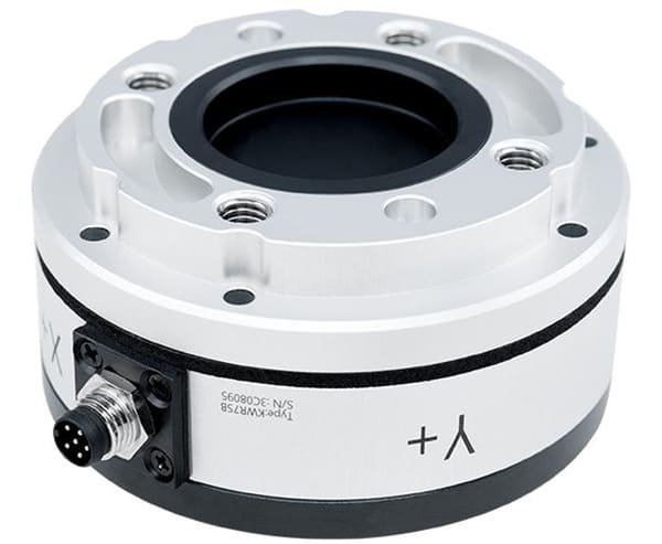
WST1304 — Six-Axis Force/Torque Sensor for Cobots
The wrist sensor I specify most often for collaborative and small industrial robots. Light enough that it does not eat the cobot’s payload margin, with a deliberately large bending-moment range for its force rating.
- Ranges: Fx/Fy 30–500 N, Fz 30–700 N, Mx/My/Mz 1.5–18 N·m across six standard variants
- Accuracy: 0.5% FS comprehensive error, 0.1% FS repeatability, 0.03% FS resolution
- Body: Ø75 × 31.5 mm, 0.26–0.36 kg, aluminium alloy, anodised
- Overload: 300% FS; IP64; 0–80 °C
- Output: RS485 / RS422 / USB / industrial Ethernet / MODBUS TCP/UDP, 12–48 VDC
- Built-in: high-precision acquisition and decoupling circuit — the unit outputs decoupled force and moment directly
Best for: deburring, polishing, peg-in-hole assembly and collision detection on cobots and small robots — the unit I reach for first, whenever the tool offset is short enough that a compact sensor still covers the moment range.
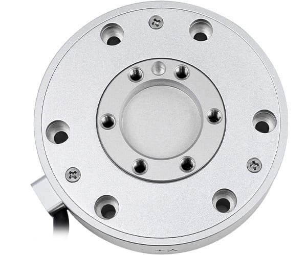
WST1306 — Industrial Robot Six-Axis Sensor
The step up in force and moment range, for industrial arms carrying real spindles, grippers and fixtures with meaningful offsets. High-strength duralumin construction, high rigidity, built-in acquisition and decoupling with direct force/moment output.
- Ranges: Fx/Fy 100–2000 N, Fz 200–2000 N, Mx/My/Mz 10–100 N·m across five variants
- Accuracy: 0.5% FS on standard variants; 0.03% FS resolution, 0.1% FS repeatability
- Body: Ø96 × 26 mm, 0.32–1.6 kg, aluminium alloy (electropolished alloy steel on the largest variant)
- Overload: 300% FS on standard variants, 200% on the 2000 N model
- Sampling: 1 kHz; IP64; 0–80 °C; 12–48 VDC
- Integration: can be paired with a serial-port server for Ethernet-linked PCs or terminals
Best for: heavy deburring, grinding and surface finishing, larger assembly stations, and any cell where the tool’s lever arm pushed the moment requirement past what a compact sensor can take — exactly the situation in the Brescia case in section 5, which ran on the 200 N / 400 N / 18 N·m variant of this family.
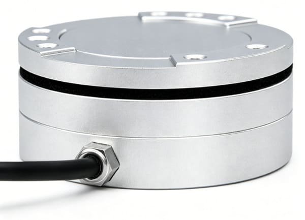
WST1303 — Ultra-Compact Six-Axis Sensor
A 46 mm diameter, 20.4 mm tall six-axis sensor weighing 60 to 70 grams — small enough for a fingertip, a test rig or a miniature wrist. Six-axis joint calibration with full crosstalk suppression, and high overload for its size.
- Ranges: Fx/Fy/Fz 50, 150 or 200 N; Mx/My/Mz 2, 5 or 7 N·m
- Performance: 0.5% FS comprehensive error, 0.03% FS resolution, 0.1% FS repeatability
- Body: Ø46 × 20.4 mm, 0.06–0.07 kg, aluminium alloy, anodised; IP64
- Overload: 300% FS; 5–80 °C; 9–24 VDC; 1 kHz sampling
- Note: the body is too small to embed the acquisition circuit, so it ships with a matching signal acquisition box in your protocol version
Best for: research and medical test rigs, haptic and tactile studies, micro-assembly and the smallest collaborative arms — anywhere a 300 g sensor would change the dynamics of the thing it is measuring.
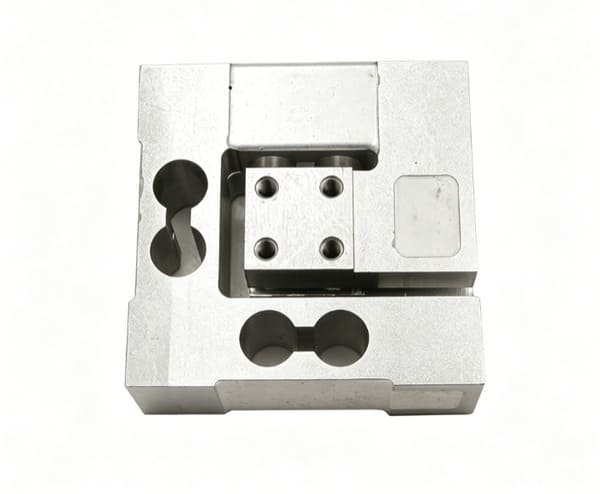
WST1301 — Three-Axis Multi-Directional Force Sensor
The honest three-axis unit for light work: Fx, Fy and Fz on one compact anodised aluminium body, with low mutual interference and a genuinely fine 0.2% FS comprehensive error. This is the sensor behind the Belluno polishing case in section 6.
- Range: 10, 20, 30 or 50 N on each of the three axes
- Performance: ±0.2% FS comprehensive, linearity and hysteresis error; 1.0 ±0.5% mV/V output
- Bridge: 350 Ω input and output; 5–10 VDC recommended, 18 VDC maximum
- Environment: −35 to +70 °C operating, −10 to +40 °C compensated; IP65
- Cable: four-wire shielded, Ø3.8 mm × 2 m; safe overload 150% FS
Best for: narrow-space multi-directional force measurement, light surface finishing with a short tool offset, touch and feel studies, and three-component force systems where the moment channels would only add cost.
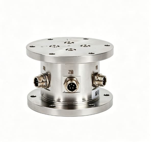
WST1302 — Dual-Flange Three-Axis Force Sensor
The heavy three-directional unit: a stainless steel dual-flange body for measuring forces in X, Y and Z where the loads are in the hundreds of kilograms, not the tens of newtons. Gold-foil strain gauge technology with low mutual interference.
- Range: X 20–500 kg, Y 20–500 kg, Z 30–1000 kg
- Performance: ≤±3.0% FS comprehensive error, ±1.0% FS linearity, ±0.05% FS/30 min creep
- Body: stainless steel, dual-flange mounting; 1.0 ±10% mV/V output
- Environment: −20 to +80 °C, −10 to +60 °C compensated; IP65
- Overload: 120% FS safe, 200% FS ultimate; Ø5 mm × 3 m shielded cable
Best for: multi-directional force detection during milling and grinding, three-component measurement on machine tools and fixtures, heavy robotic arms, and three-way force systems in industrial R&D.
11. FAQ
What is the difference between a 3-axis and a 6-axis force sensor?
A three-axis sensor measures Fx, Fy and Fz — the three orthogonal force components. A six-axis sensor measures those three forces plus three moments (Mx, My, Mz) about the same axes, so it reports the complete wrench and where the load is acting relative to the reference point. Three axes is enough when the tool has a short offset and the wrist hardly rotates. Six axes becomes necessary as soon as the tool has a real lever arm, an off-centre mass, or a pose range wide enough that gravity migrates between channels. A six-axis unit typically costs two to four times an equivalent three-axis sensor.
What is crosstalk in a multi-axis sensor, and what value should I accept?
Crosstalk is the fraction of a load applied on one axis that appears on another — press on Fz and the Fx channel moves slightly. It exists because all six bridges share one machined elastic body. Good industrial sensors keep residual crosstalk below 2% of full scale, and well-calibrated units reach below 1% FS after decoupling. Ask for the number after decoupling and ask whether it is included in the quoted accuracy, because a datasheet that lists 0.1% linearity alongside 5% crosstalk is really a 5% sensor for multi-axis work.
What do I do with the 6×6 decoupling matrix?
Load it into the device that converts your raw bridge signals into forces and moments. The relationship is F = A · U + B, where U is the vector of six raw outputs, A is the 6×6 calibration matrix, B is the zero offset vector and F is the true force/moment vector. In our digital units that maths runs inside the sensor’s acquisition electronics, so the output is already decoupled. If you buy an analogue version and do the conversion in your own card or controller, the matrix must be entered there — per serial number, not per model.
How do I choose the moment range on a six-axis sensor?
Multiply. Take the maximum process force and multiply it by the distance from the sensor’s reference plane to the point where that force is applied. Do the same for the weight of the tool acting at its own offset, and add a term for tangential or friction forces. That sum is your working moment, and it is usually larger than people expect: 50 N at a 130 mm offset is 6.5 N·m before the tool’s own weight is counted. Size the moment channel so the working point sits at 20–50% of full scale, and remember that shortening the tool offset is often cheaper than buying the next range up.
What sampling rate do I need for robot force control?
Well above your control-loop rate, and the honest answer depends on the process. Assembly and insertion loops are comfortable at 100–200 Hz sampling with a control cycle in the millisecond range. Material-removal processes — grinding, deburring, sanding — benefit from 1 kHz, because you are trying to observe a contact force superimposed on tool and spindle vibration. Two cautions: never filter so heavily that the added phase lag destabilises the loop, and remember that a sensor’s headline 1 kHz is only real if the interface and the controller can actually carry it.
Can I mount a six-axis sensor directly on my robot flange?
Usually yes, and many developers offer a mounting pattern to DIN ISO 9409-1, the standard robot tool flange. Check three things: the bolt circle and centring features match your specific flange size; the mounting faces are flat and parallel, with no shims or soft washers; and the bolts are tightened diagonally to the supplier’s torque figure. If you use an adapter plate instead of the standard pattern, make sure it is stiff enough not to add compliance to the load path — a flexible adapter between a rigid sensor and a rigid tool defeats the measurement.
Does fitting a six-axis sensor make my cobot cell compliant with ISO/TS 15066?
No, and this is the line we are most careful about. ISO 10218-1 covers safety requirements for industrial robots and ISO/TS 15066 specifies the force and power limiting used in collaborative operation. A force/torque sensor can provide the measurement a safety function acts on, but a general-purpose strain-gauge sensor is not a safety-rated device. The safety function, its performance level, its validation and its documentation belong to whoever designs and certifies the cell. We supply the transducer, the decoupling matrix and a traceable calibration record — not the safety rating.
Can you supply the sensor with a data acquisition box, and what interfaces are available?
Yes. Our six-axis families output on RS485, RS422, USB, industrial Ethernet and MODBUS TCP/UDP, at 12–48 VDC, with the acquisition and decoupling electronics built into the sensor where the body is large enough and supplied as a separate box where it is not — the 46 mm WST1303 is the clearest example, since there is no room inside it. Capacities, flange patterns, cable length and exit direction, and connector type are all customisable. Tell us the controller you are feeding and the protocol it expects, and we will match the interface rather than leaving you to convert it.
Send me the tool, not the datasheet
Six numbers size a multi-axis sensor: peak force per axis, the distance from the sensor reference plane to the contact point, the mass and centre of gravity of everything downstream, the wrist pose range, your controller cycle time and the interface it wants. Give me those — a sketch on a photo of the tool is fine — and I will come back with a range recommendation, a mounting drawing and the moment arithmetic worked out.
We supply the sensing layer: multi-axis force/torque sensors, load cells, force sensors, transmitters, junction boxes and indicators — with a per-unit 6×6 decoupling matrix and calibration record. Trial orders welcome.
Get a multi-axis sensor sized for your cell →
Email Robin directly
VektorForce · Multi-axis force/torque sensors, load cells, force sensors, junction boxes, transmitters & indicators · www.vektorforce.com