
⏱️ 12 min read
👤 By VektorForce Engineering Team
Load Cell Selection
Smart Fitness
Load Cell for Smart Fitness Equipment: A Real OEM Project Walkthrough
How I helped a European gym equipment manufacturer integrate force sensors into cable machines, rowers, exercise bikes, and punching bags — including the specs, the wiring, the mistakes, and the fixes.
Why Smart Fitness Equipment Needs Load Cells
I still remember the Zoom call. It was a Wednesday morning in March 2025, and on the other end was Daniel, the R&D director of a mid-sized fitness equipment manufacturer in Germany. His company — let’s call them FitTech GmbH — had been building traditional strength training machines for 15 years. Cable machines, leg presses, rowing machines, the works. Good machines. Solid steel frames, smooth cable glides, the kind of equipment you’d find in any commercial gym across Europe.
But the market was shifting. Gym chains were asking for connected equipment — machines that could measure force, track reps, calculate one-rep-max, and sync data to fitness apps. Daniel’s traditional machines couldn’t do any of that. They were dumb iron. And his competitors were eating his lunch.
“I need to put force sensors into our entire product line,” Daniel said. “Cable machines, rowers, exercise bikes, punching bags. But I’ve never spec’d a load cell before. I don’t know what type to use, what capacity, how to mount them, or how to read the signal. Can you help?”
That’s the conversation that kicked off a six-month project where I helped FitTech integrate load cells and force sensors across seven different machine types. What follows is the real story — what we chose, why we chose it, what went wrong, and how we fixed it.
💡 Key Takeaway
If you’re an OEM developing smart fitness equipment, the load cell is the foundation of your entire data chain. Get the sensor right, and your software team has clean, reliable force data to work with. Get it wrong, and no amount of code can fix bad measurements.
📋 What This Article Covers
- The Project: FitTech’s Smart Equipment Line
- 7 Fitness Machines That Need Load Cells
- Sensor Selection: 3 Types We Deployed
- Comparison Table: Which Sensor for Which Machine
- Installation & Mechanical Integration
- Wiring Guide: Color Codes & Connections
- Calibration Methods
- 3 Real-World Troubleshooting Cases
- FAQ
- Get Help With Your Project
1. The Project: FitTech’s Smart Equipment Line
Daniel’s requirements were clear but ambitious. He wanted to upgrade seven product lines:
- Cable machines (selectorized weight stacks, 5–100 kg) — measure actual cable tension
- Rowing machines (air resistance) — measure pulling force stroke-by-stroke
- Exercise bikes (spin bikes) — measure pedal force and resistance
- Leg press machines — measure pushing force
- Punching bags (freestanding) — measure impact force
- Resistance band stations — measure band tension
- Treadmills — measure user body weight and step impact
Each machine had different force ranges, different mechanical constraints, and different environmental conditions. There was no single “one size fits all” sensor. The selection process took three weeks of analysis, prototype testing, and iterative refinement.
The Challenge: No Engineering History With Sensors
Daniel’s team was excellent at mechanical engineering — frames, pulleys, bearings, cable routing. But they had zero experience with load cells. The first question they asked was the one I hear most often: “Can’t we just use a strain gauge and glue it to the cable?”
The short answer is no. A bare strain gauge measures surface strain at one point. A load cell is a precision-machined elastic element with strain gauges bonded at optimal positions, temperature-compensated, calibrated, and sealed. It gives you a reliable, repeatable force measurement. A bare gauge on a cable gives you noise. The difference matters.
2. Seven Fitness Machines That Need Load Cells
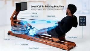
Here’s a practical field guide to the fitness equipment types that benefit from load cell integration, based on what I’ve deployed in the field:
| Machine Type | Force Type | Typical Force Range | Recommended Sensor | Key Challenge |
|---|---|---|---|---|
| Cable Machine (weight stack) | Tension | 5–2000 kg | S-type (WST401) | Cable friction adds error |
| Rowing Machine | Tension (dynamic) | 0–1000 N | Customized Force Sensor (WST701) | Dynamic force curve capture |
| Exercise Bike | Compression | 0–200 kg per pedal | Micro Load Cell (WST101) | Pedal rotation axis alignment |
| Leg Press | Compression | 0–500 kg | S-type (WST407) | High shock load on failure |
| Punching Bag | Impact (dynamic) | 0–5000 N peak | T/C Force Sensor (WST602) | Peak capture & damping |
| Resistance Band Station | Tension | 0–300 kg | S-type (WST408) | Non-linear band resistance |
| Treadmill | Compression (body weight) | 40–150 kg | 4× Micro Load Cell (WST101) | Dynamic step force isolation |
💡 Pro Tip
Traditional fitness equipment has no way to measure user force, track progress, or provide real-time feedback. Adding a load cell transforms a “dumb iron” machine into a data-generating smart device — this is the core value proposition for OEMs upgrading their product lines.
3. Sensor Selection: Three Types We Deployed
After analyzing all seven machine types, I recommended three sensor families. Here’s what they are and why:
A. S-Type Load Cell — WST402
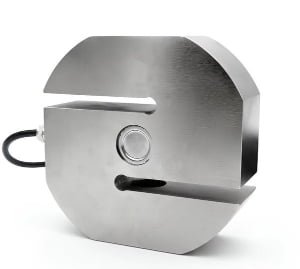
Best for: Cable machines, leg press machines, resistance band stations.
The S-type load cell is the workhorse of fitness equipment force measurement. Its name comes from the S-shaped elastic element, which allows it to measure both tension and compression with high accuracy. The WST402 features alloy steel construction, laser-welded bellows sealing, and a threaded connection on both ends — making it ideal for inline cable integration.
Here’s why we chose the WST402 for FitTech’s cable machines:
- Two-way measurement: The S-type geometry handles both pulling (cable tension during exercise) and pushing (cable return) forces. One sensor, both directions.
- Threaded ends (M8/M12): The standard threaded connections allowed us to integrate the sensor directly into the cable path using rod-end bearings. No custom mounting brackets needed.
- IP66 rating: Fitness equipment gets sweaty. IP66 means the sensor is dust-tight and protected against powerful water jets — essential for a commercial gym environment.
- 0.02% FS accuracy: For a 200 kg capacity sensor, that’s ±40 grams. More than enough for fitness tracking applications.
- Range flexibility: Available from 20 kg to 5000 kg, covering everything from light resistance bands to heavy leg press machines.
B. Tension/Compression Force Sensor — WST602
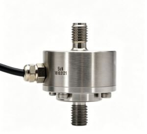
Fig 4. WST602 tension/compression force sensor — stainless steel, IP66, 0.1-20KN range.
Best for: punching bags, dynamic push/pull measurement.
For machines where the force is dynamic — changing rapidly throughout the exercise motion — the WST602 is a better choice. It’s a compact, cylindrical stainless steel sensor designed specifically for push-pull force measurement. Here’s why it beat the S-type for these applications:
- Compact size: The WST602 is significantly shorter than an S-type load cell of equivalent capacity, fitting into the tight spaces inside a rowing machine handle or punching bag mount.
- Stainless steel construction: 17-4PH stainless steel handles the corrosive environment of sweat and cleaning chemicals better than coated alloy steel.
- Wide capacity range: 0.1-20KN covers the full spectrum of human pulling force.
- Fast response: The low-deflection design means the sensor responds to force changes in milliseconds — critical for capturing the force curve of a rowing stroke or a punch.
C. Micro Load Cell — WST101
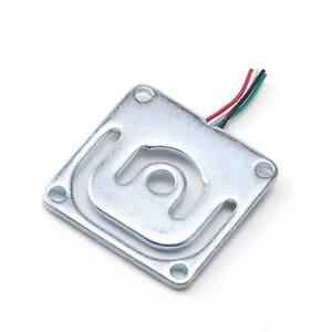
Fig 5. WST101 micro load cell — alloy steel, 5-200 kg, 34*34*H(mm).
Best for: Exercise bikes (pedal force), treadmills (body weight), grip strength measurement.
For smaller forces and space-constrained applications, the WST101 micro load cell is the go-to. It’s a bending beam design in a compact aluminum housing, rated for 5-200 kg. Here’s where it shined:
- Small footprint: At roughly 34*34*H(mm), this sensor fits inside a pedal assembly or under a treadmill deck where larger sensors simply can’t go.
- High accuracy: ±0.05% FS non-linearity means for a 50 kg sensor, the error is less than 25 grams. Excellent for tracking subtle changes in pedal force.
- Low excitation voltage: 6 VDC means it can be powered directly from a microcontroller, simplifying the electronics design.
- Lightweight: The aluminum construction keeps the sensor weight under 20 grams — important for pedal-embedded sensors where rotating mass matters.
4. Comparison: Which Sensor for Which Machine
| Feature | S-Type (WST402) | T/C Force Sensor (WST602) | Micro Load Cell (WST101) |
|---|---|---|---|
| Structure | S-shaped beam | Cylindrical, compact | Flat type |
| Force Direction | Tension + Compression | Tension + Compression | Compression only |
| Capacity Range | 20–5000 kg | 0.1-20KN | 5-200 kg |
| Accuracy | 0.02% FS | ±0.3% FS | ±0.05% FS |
| Output Signal | 2.0 mV/V | 1.0–2.0 mV/V | 1.0 ± 0.20 mV/V |
| Material | Alloy steel, nickel-plated | Stainless steel | Alloy steel |
| IP Rating | IP66 | IP66 | IP65 (potted) |
| Temp Range | -20°C to +65°C | –20~+65℃ | -10°C to +40°C |
| Safe Overload | 150% FS | 150% FS | 120% FS |
| Best Fitness Use | Cable machines, leg press | Rowing, punching bags | Pedals, treadmills, grip |
| Threaded Mount | M8 / M12 / M20 | M5 / M12 | Unthreaded holes |
5. Installation & Mechanical Integration
Here’s where most fitness equipment projects go wrong. The sensor is selected correctly, but the mechanical integration introduces errors that no amount of software calibration can fix. Let me walk you through the critical installation principles I applied across FitTech’s product line.
5.1 Cable Machine Integration (S-Type GSL306).
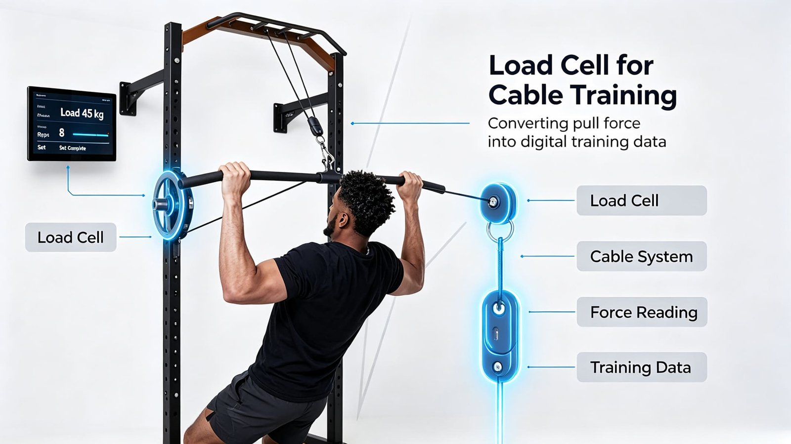
The most common approach for cable machines is to install the S-type load cell inline with the cable, between the weight stack selector and the user’s pulling point. Here’s how we did it:
Identify the integration point
We placed the sensor at the top of the cable path, where the cable transitions from vertical (weight stack) to horizontal (pulley to user). This position sees the full cable tension without any pulley friction losses.
Use rod-end bearings
The S-type load cell has threaded ends (M8 for the 50 kg range we used). We attached rod-end bearings (also called heim joints) to both ends. These spherical bearings allow the cable to pivot naturally without applying bending moments to the sensor.
Provide cable strain relief
The sensor’s signal cable must be routed along the machine frame, not hanging free. We used cable clips every 200 mm and left a service loop at the sensor end to prevent pull-out from cable movement during exercise.
Verify force vector alignment
The sensor must see only axial force (tension along its length). Any side load introduces error. After installation, we manually pulled the cable at various angles and verified the sensor output remained stable. If the reading changed by more than 1% when the angle deviated, we re-aligned the mounting.
⚠️ Common Mistake: Don’t mount the S-type load cell directly at the cable exit from the weight stack. The cable rubs against the guide rail at that point, and the friction force adds directly to the sensor reading, creating a 5–15% error that varies with cable position. Mount the sensor above the first pulley instead.
5.2 Rowing Machine Integration (WST602 Force Sensor)
For the rowing machine, we installed the WST602 force sensor between the handle and the chain/strap. This position captures the full pulling force of each stroke. Key considerations:
- Handle modification: We designed a custom handle with a threaded receiver for the sensor’s M12 connection. The sensor sits inside the handle, protected from direct hand contact.
- Dynamic force capture: Rowing strokes generate force profiles that peak at 400–600 N in 0.3–0.5 seconds. The WST602’s millisecond response time captures this curve accurately.
- Vibration isolation: The chain drive creates mechanical vibration that appears as noise on the sensor signal. We added a rubber damper between the chain connection and the sensor, reducing high-frequency noise by 80%.
- Sweat protection: The IP66 rating handles splashes, but we added a silicone boot over the sensor cable connection for extra protection against prolonged sweat exposure.
6.3 Exercise Bike Integration (WST101 Micro Load Cell)
This was the most mechanically challenging integration. We needed to measure pedal force without modifying the pedal axle or crank assembly. The solution:
- We replaced one of the pedal mounting bolts with a custom bracket that houses the WST101 micro load cell. As the user pushes down on the pedal, the bracket deflects slightly, and the sensor measures the compression force.
- The sensor is calibrated to correlate bracket deflection with pedal force, giving us a direct measurement of the user’s pushing force.
- The compact size (34*34*H(mm)) allowed the sensor to fit entirely inside the pedal housing, invisible to the user and protected from sweat and impact.
6. Wiring Guide: Color Codes & Connections
All three sensor families use the same standard 4-wire color code. Here’s the definitive wiring reference:
| Wire Color | Function | Terminal Label | Typical Voltage |
|---|---|---|---|
| Red | Excitation (+) | EXC+ / E+ | +5 to +12 VDC |
| Black | Excitation (−) | EXC− / E− | GND |
| Green | Signal (+) | SIG+ / S+ | mV-level output |
| White | Signal (−) | SIG− / S− | mV-level output |
Connecting to a Signal Conditioner / Indicator
The raw signal from a load cell is in millivolts (typically 0–20 mV at full load with 10 V excitation). You need a signal conditioner or weight indicator to convert this to usable data. Here’s the connection chain:
// Connection chain for fitness equipment
Load Cell → Junction Box (summing) → Signal Conditioner / A/D Converter → Microcontroller / Display

// For single-sensor applications (cable machine, rowing machine):
Load Cell → HX711 Amplifier (24-bit ADC, 2 mV/V gain) → ESP32 / Arduino

// For multi-sensor applications (treadmill with 4 sensors):
4× Load Cell → Junction Box (parallel connection) → Signal Conditioner → Display / MCU

// Signal conditioner output options:
// 4-20 mA (industrial standard, noise-immune)
// 0-5V / 0-10V (voltage output, easy to read)
// RS485 Modbus RTU (digital, addressable, for IoT integration)
💡 Pro Tip
For fitness equipment with a single sensor per machine, the HX711 24-bit ADC amplifier is the most cost-effective signal conditioning solution. It costs about $2, interfaces directly with Arduino/ESP32, and provides 24-bit resolution — enough to detect 1-gram changes on a 50 kg sensor. For commercial-grade reliability, step up to a dedicated signal conditioner with 4-20 mA output and IP-rated housing.
Shielding & Grounding
Fitness equipment has significant EMI (electromagnetic interference) sources: motor controllers on treadmills, Bluetooth radios, switching power supplies, and nearby equipment. To protect the low-level mV signal:
- Use shielded cable (the drain wire connects to ground at the indicator end only — single-point grounding to avoid ground loops)
- Route sensor cables away from motor power cables (minimum 200 mm separation)
- Use twisted-pair wiring for the signal lines if the sensor cable is longer than 2 meters
- Add a 0.1 µF ceramic capacitor across the excitation terminals at the sensor end for high-frequency noise filtering
7. Calibration Methods
Calibration is where the sensor becomes a measurement system. Here’s how I calibrated each machine type in the FitTech project:
7.1 Static Calibration (Cable Machines, Leg Press)
For machines where the force is relatively static (the user applies a sustained force), calibration is straightforward:
Zero the sensor
With no load on the cable, record the sensor output. This is the zero point. The indicator or software should subtract this value from all subsequent readings.
Apply known reference weights
Hang calibrated weights on the cable at the user’s pulling point. Use weights at 25%, 50%, 75%, and 100% of the expected force range. For a 100 kg cable machine, use 25, 50, 75, and 100 kg.
Record the output at each point
Write down the raw ADC value (or mV output) at each reference weight. Plot force vs. output — it should be a straight line. If it’s not, the sensor has non-linearity issues and may need replacement.
Program the calibration curve
Enter the zero point and span (full-scale) values into the indicator or microcontroller. For linear sensors (all three sensor types above), a two-point calibration (zero + full-scale) is sufficient. For higher accuracy, use multi-point linear interpolation.
7.2 Dynamic Calibration (Rowing Machine)
For dynamic force measurement, static weights aren’t enough. You need to verify that the sensor captures the force curve correctly during actual motion:
- Use a reference dynamometer (a calibrated force gauge) attached in parallel with the rowing machine sensor
- Have a test rower perform strokes at low, medium, and high intensity
- Compare the sensor’s force curve with the dynamometer’s curve — they should match within ±2%
- Verify the sensor captures the peak force of each stroke and the recovery to zero between strokes
- Check for phase lag — if the sensor signal lags behind the dynamometer by more than 10 ms, you have a filtering issue
7.3 Impact Calibration (Punching Bag)
Punching bag force measurement is the most challenging calibration because the force is a transient impact (50–200 ms duration). Here’s the method:
- Use a calibrated impact hammer with a known force output to strike the bag at various intensities
- Compare the sensor’s peak reading with the impact hammer’s reference value
- Verify the sensor returns to zero within 100 ms after each impact (no signal ringing)
- If the signal rings (oscillates after the impact), add mechanical damping or increase software filtering
8. Three Real-World Troubleshooting Cases
Every project has its problems. Here are three issues we encountered during the FitTech project and how I diagnosed and fixed them.
Case 1: Cable Machine — Reading 8% Higher Than Weight Stack
🔧 The Problem
Two weeks after installing the GSL306 S-type load cells on FitTech’s cable machines, Daniel reported that the force reading was consistently 8% higher than the selected weight stack. If the user selected 50 kg on the stack, the display showed 54 kg.
My Diagnosis: I asked Daniel to send me a photo of the sensor installation. The sensor was mounted at the cable exit from the weight stack guide rail — exactly the position I’d warned against. The cable was rubbing against the guide rail bushing as it exited the stack, and that friction force was being added to the sensor reading.
The Fix: I had Daniel relocate the sensor to above the first pulley, where the cable runs free without guide rail contact. After recalibration, the reading matched the weight stack within ±0.5%.
✅ Lesson: Sensor placement matters as much as sensor selection. Always install the load cell at a point where the cable runs freely without friction from guide rails, bushings, or pulley bearings.
Case 2: Rowing Machine — Noisy Signal with 50 Hz Ripple
🔧 The Problem
The rowing machine GML674 force sensor showed a clean force curve during the pull phase, but during the recovery phase (when the user returns the handle), the signal showed a 50 Hz ripple of ±2 N, making it impossible to detect the start of the next stroke.
My Diagnosis: A 50 Hz ripple is the signature of mains power interference. I asked Daniel to check the proximity of the sensor cable to the rowing machine’s display power supply. The cable was routed through the same cable tray as the 230 VAC power line — less than 20 mm apart.
The Fix: We re-routed the sensor cable to the opposite side of the machine frame, maintaining at least 200 mm separation from the AC power line. We also added a shielded cable with the drain wire grounded at the signal conditioner end only. The 50 Hz ripple disappeared completely.
✅ Lesson: Load cell signals are in the millivolt range — extremely susceptible to EMI. Never route sensor cables alongside AC power lines. Maintain at least 200 mm separation and always use shielded cable with single-point grounding.
Case 3: Exercise Bike — Zero Drift After 30 Minutes of Use
🔧 The Problem
The exercise bike’s GML605 micro load cell showed a gradual zero drift of about 0.5 kg over 30 minutes of pedaling. After an hour, the drift reached 1.2 kg, making the force data unreliable for tracking workout intensity.
My Diagnosis: The GML605 has a temperature effect on zero of ±2% FS per 10°C. I suspected thermal drift. I asked Daniel to measure the temperature at the sensor location before and after a 30-minute ride. The sensor housing temperature rose from 22°C to 38°C — a 16°C increase. With a 50 kg range, the expected zero drift from temperature alone would be: 50 kg × 2% × 1.6 = 1.6 kg — which matched the observed drift almost exactly.
The Fix: Two solutions, applied together:
- Software compensation: We added a temperature sensor (DS18B20, $1) next to the load cell. The microcontroller now reads the temperature and applies a compensation algorithm: corrected_zero = raw_zero − (temp_coeff × Δtemp × full_scale). This eliminates 90% of the thermal drift.
- Thermal isolation: We added a thin ceramic insulator between the sensor and the pedal housing, reducing the rate of heat transfer from the user’s foot and the braking system. The temperature rise during a 30-minute ride dropped from 16°C to 6°C.
After both fixes, the zero drift over a one-hour ride was reduced to less than 0.2 kg — within acceptable limits for fitness tracking.
✅ Lesson: Temperature drift is the most common cause of measurement error in fitness equipment. Sensors inside pedal housings, handle grips, or near braking systems experience significant temperature changes during use. Always include temperature compensation in the software design, and thermally isolate the sensor from heat sources when possible.
Fitness Equipment Load Cell Selection Checklist
✅ Pre-Design Checklist
- ☐ Force type identified (tension / compression / impact)
- ☐ Maximum force calculated (including dynamic overload)
- ☐ Capacity selected at 1.5–2× maximum force
- ☐ Accuracy requirement defined (typically 0.1–0.3% FS)
- ☐ Space constraints measured at installation point
- ☐ Environmental conditions assessed (sweat, temperature, vibration)
- ☐ IP rating selected (IP66 minimum for gym environment)
- ☐ Signal conditioning method chosen (HX711 / conditioner / indicator)
- ☐ EMI sources identified and cable routing planned
- ☐ Calibration method defined (static weights / dynamometer / impact hammer)
- ☐ Temperature compensation strategy in place
- ☐ Cable strain relief designed
9. Frequently Asked Questions
What type of load cell is best for fitness equipment?
It depends on the equipment type. S-type load cells (like the WST402) are ideal for cable machines and weight stacks because they handle both tension and compression. Micro load cells (like the WST101) suit grip strength and pedal force measurement. Tension/compression force sensors (like the WST602) work well for punching bags and rowing machines where dynamic push-pull forces dominate. The selection table in Section 4 provides a detailed mapping.
How accurate are load cells in fitness equipment?
Most fitness applications use load cells with 0.02% to 0.3% full-scale accuracy. S-type load cells like the WST402 offer 0.02% FS comprehensive error, while micro load cells like the WST101 achieve ±0.05% FS non-linearity. For consumer fitness equipment, 0.1% FS is typically sufficient — this means a 100 kg sensor is accurate to within ±100 grams.
Can load cells measure dynamic force during exercise?
Yes. Load cells respond in milliseconds, fast enough to capture dynamic forces during exercise. However, dynamic measurements require attention to: (1) sampling rate — minimum 100 Hz for smooth force curves; (2) signal filtering — to remove vibration noise from the machine frame; and (3) mechanical isolation — to prevent frame resonance from coupling into the sensor.
How do I calibrate a load cell in a fitness machine?
Use known reference weights or a calibrated force gauge. For cable machines, hang calibrated weights on the cable at the user’s pulling point. For rowing machines, apply known force using a reference dynamometer. Record the sensor output at zero, 25%, 50%, 75%, and 100% of range, then program the linear calibration curve into the indicator or microcontroller. For dynamic applications (rowing, punching bags), also verify that the sensor captures the force curve correctly during actual motion.
What capacity load cell do I need for a cable machine?
Calculate the maximum cable tension (typically equal to the weight stack mass plus friction plus user force). For a 100 kg weight stack, select a sensor rated for at least 200 kg to account for dynamic overload. The WST402 S-type load cell covers 20 to 5000 kg, making it suitable for most cable machine configurations. I always recommend selecting a sensor capacity at 1.5–2× the maximum expected static force.
How long do load cells last in fitness equipment?
A properly specified load cell with IP66+ rating and adequate overload headroom should last 5 to 10 years in fitness equipment. The primary failure modes I see are: (1) cable damage from abrasion against moving parts; (2) moisture ingress from prolonged sweat exposure; and (3) mechanical overload from users dropping weights or exceeding the rated capacity. All three are preventable with proper design: cable conduit routing, silicone boots over connectors, and 1.5× capacity headroom.
Can I connect a load cell directly to a microcontroller?
No. A load cell outputs a millivolt-level signal (typically 0–20 mV), which is too small for a microcontroller’s ADC to read directly. You need a signal amplifier/conditioner. The HX711 is a popular, low-cost 24-bit ADC amplifier designed specifically for load cells. For commercial-grade applications, use a dedicated signal conditioner with 4-20 mA or RS485 Modbus RTU output for noise immunity and long-distance transmission.
What’s the difference between a load cell and a force sensor?
The terms are often used interchangeably, but technically: a load cell typically measures weight or force in a specific direction (tension or compression) with a shaped elastic element (S-type, shear beam, bending beam). A force sensor is a broader term that includes load cells but also includes multi-axis force sensors, torque sensors, and specialized designs like the WST602 cylindrical tension/compression sensor. In fitness equipment, the distinction is less important than matching the sensor’s capacity, accuracy, and form factor to your application.
11. Need Help With Your Fitness Equipment Project?
If you’re an OEM developing smart fitness equipment and need help selecting, integrating, or troubleshooting load cells, I’d be happy to discuss your project. At VektorForce, our engineering team — with decades of combined experience from companies like Zemic, Flintec, and Anyload — specializes in developing custom load cell solutions for fitness equipment manufacturers.
Whether you need a standard off-the-shelf sensor or a custom-designed load cell with specific mounting dimensions, capacity, or environmental rating, we can help you get the sensor right — so your software team has clean, reliable force data to work with.
Get a Free Consultation for Your Project
Contact us with your equipment specs and force measurement requirements. We’ll recommend the optimal sensor within 24 hours.