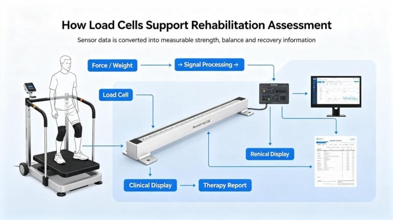


Load Cells for Infant Incubators: Weighing a Patient You Never Take Out of the Box
An incubator’s in-bed scale has to resolve a few grams on a baby that is tethered to a ventilator, lying on bedding that is getting heavier, inside a box whose whole job is to be 17 °C hotter and 90 % wetter than the room. The load cell is the easiest part of that problem. This is what I have learned sizing them for OEMs who build the box.
October 10, 2026
14 sections · 3 field cases
Read time ~14 min
Most of the weighing problems I am asked to solve are industrial: a hopper that reads light, a tank that drifts, a batching scale that has been “wrong since the summer”. A neonatal incubator is not like that. It is the only weighing application I work on where the scale lives inside the machine it is measuring, and where the person reading the number is trying to make a clinical decision from it.
I do not build incubators, and I am not going to pretend I do. I make load cells, junction boxes and the electronics that go behind them, and I sell them to the people who do build the box. That position has one advantage: I see the same three or four mistakes across different OEMs, in different countries, and they are almost never about the load cell.
So this is not a product page. It is the design reasoning I would walk you through, plus the three projects where it went wrong and what actually fixed them.
The short version: on an incubator tray, the load cell contributes roughly a third of the total error. The other two thirds are the boundary you draw around what gets weighed, and the protocol used to weigh it. Both of those are cheaper to fix than any sensor upgrade, and both are invisible on a datasheet.
What’s in this article
2. The weighing boundary: four questions
3. Error #1 — everything plugged into the baby
4. Error #2 — a tare that is never the same twice
5. Your accuracy spec picks the capacity
6. Three cells, not four
7. Living inside a 95 % RH box at 37 °C
8. Case: the baby who gained while losing
9. Case: the rotating mattress and 24 g
10. Case: the tubing that was not the baby
11. The component you can never change again
12. What I supply, what I do not, and the BOM line
13. Questions I get asked
14. Components mentioned in this article
1. What an in-bed scale actually has to do
Start with what the market already ships, because it sets the target far more honestly than any clinical wish list. One of the best-known incubator/warmer platforms on the market publishes this for its integrated in-bed scale:
| Published in-bed scale spec | Value | What it implies for the sensor |
|---|---|---|
| Accuracy | ±10 g (±0.35 oz) | This is the whole error budget. Not the sensor’s — the system’s. |
| Range | 300 g to 8 kg | A 0.125 %FS window. Wide tare, narrow payload. |
| Resolution | 10 g (factory) or 5 g (non-EU, user-selectable) | Resolution and accuracy are the same number here. That is deliberate. |
Two details in that table are worth more than the rest put together. First, the floor of the weighing range is 300 g, not zero — because below that nobody expects the number to mean anything. Second, in the EU that same scale reports 5 g up to 5 kg and 10 g above it, and the resolution is not user-selectable. That is not an engineering limit; it is a metrology one. The manufacturer’s own note tells EU and EFTA customers to check their local Non-Automatic Weighing Instrument (NAWI) regulations for how and how often the scale must be calibrated.
Now the clinical context, because it explains why ±10 g is considered good enough:
- Term birth weight is roughly 2,700–3,850 g. A preterm infant in an incubator may be 1,000–1,500 g.
- Physiological weight loss in the first days is 7–10 % of birth weight in term infants and commonly 8–15 % in preterms, bottoming out around day 3–5.
- Expected gain after that is 15–20 g/kg/day, with 20–30 g/kg/day associated with better neurodevelopmental outcomes.
- Day-to-day fluctuation in the same infant, measured the same way, is quoted at 20–30 g.
Read those last two lines together. On a 1,500 g infant, the daily target is 22–30 g. The day-to-day noise is 20–30 g. The signal and the noise are the same size — which is exactly why the scale is specified at ±10 g and why nobody should ever make a decision from one reading. The number is a data point in a trend, and the trend is what the clinicians act on.
What that means for the sensor you buy: you are not being asked for a 0.01 % instrument. You are being asked for a sensor whose contribution to a ±10 g system budget is small, that is repeatable across days, and that does not move when the box gets hot. Those are three different specifications, and “0.05 %FS” only covers the first one.
2. The weighing boundary: four questions that decide the whole design
I ask for one drawing before I will quote a single load cell for an incubator. It is not a mechanical drawing. It is a line drawn around the parts that get weighed, with the weighing boundary marked on it.
The US code that defines this device is refreshingly concrete about what is inside the box: “a rigid boxlike enclosure in which an infant may be kept in a controlled environment … may include an AC-powered heater, a fan to circulate the warmed air, a container for water to add humidity, a control valve through which oxygen may be added, and access ports for nursing care.” (21 CFR 880.5400). Heater, fan, water, ports. Three of those four are things that cross a weighing boundary.
So once the line is drawn, I ask four questions:
| Question | What it finds | Typical answer |
|---|---|---|
| 1. What sits on the platform? | Tare mass and its variability | Tray + mattress + bedding + baby. The bedding changes every shift. |
| 2. What touches it from outside? | Transfer error — force that belongs to something else | Ventilator circuit, IV line, SpO2 lead, temperature probe, X-ray cassette, drawer rail, a hand in the port. |
| 3. What changes mass inside the line? | Slow drift that looks like physiology | Condensate, humidifier water, spilled feed or IV fluid, a wet nappy. |
| 4. What changes the stiffness of the line? | Errors that depend on how the bed is positioned | Mattress tilt, 360° rotation, cable loops, an inserted X-ray tray. |
Questions 1 and 2 are the ones everybody thinks about. Questions 3 and 4 are the ones that generate the support emails, because they produce numbers that are plausible. A baby gaining 90 g overnight is physiologically possible. It is only wrong when you compare it with yesterday’s number from a different scale — which is exactly what a NICU does.
The test that finds almost all of this, for free: put a certified 2 kg weight on the tray and read it with the bed flat, then tilted 12°, then rotated 90°; empty, then half full; with the tubing connected and draped, then supported off the tray. Six readings, ten minutes, no tools. Every one of the three cases below would have been caught by this, before the first unit shipped.
3. Error #1 — everything plugged into the baby
A neonate in an incubator is not a free body. On any given day it may be attached to a ventilator circuit (often with heated-wire tubing and a water trap), an IV line, a nasogastric tube, ECG leads, a SpO2 cable, and a skin temperature probe. A typical incubator canopy offers eight tubing access ports for exactly this reason.
Every one of those is a potential spring between the baby and the outside world. And the conversion is brutally simple:
1 newton of tension in a tube = 102 g on the scale.
A ventilator circuit dressed across the edge of the mattress tray, or a cable that has been pulled snug into a port, carries somewhere between 0.5 N and 5 N without anybody noticing. That is 50 g to 500 g — five to fifty times the entire ±10 g accuracy specification of the scale.
The direction matters, and it is not always obvious. Tension pulling up on the baby’s chest makes the baby look lighter. A loop of tubing resting on the tray makes the baby look heavier. Both are the same failure. The dangerous version is the one that is stable, because a stable error gets accepted as the truth.
This is not one hospital getting it wrong. A survey of all 208 UK neonatal units, published in Pediatric Research, found that admission weights were taken on in-incubator scales in 47 units (22 %) and on bedside scales in 144 (69 %) — but only 54 units (25 %) took attached equipment into account when assigning a birth weight. The other 154 units (74 %) did not, and the paper’s own conclusion is that “birth weights assigned by the majority of UK neonatal units are overestimated.” Three units had no measurement at all for babies arriving already intubated and used an estimated weight.
That survey is from 2011 and practice has moved since. The physics has not. As long as the equipment attached to the baby is heavier than the resolution you are claiming, the weighing method is part of the measurement, and no load cell can be accurate enough to make it not matter.
What actually fixes it (and it is not electronics): a tubing support arm clamped to the incubator frame, outside the weighing boundary, so the loop’s weight and tension land on the frame instead of the tray; silicone port grommets sized so the tube passes with a service loop below the port, not a straight taut run; and one sentence in the IFU telling staff to support the circuit before weighing. Case 3 below is exactly this.
4. Error #2 — a tare that is never the same twice
Here is a number that reframes the whole application. Clinical output guidance for newborns converges on six or more heavy wet nappies a day by the end of the first week. Published figures for a wet nappy are 30–60 g. Six of those is 180–360 g per day.
On a 1,200 g preterm, that is 15–30 % of its own body weight in urine, every 24 hours. Against a daily growth target of 15–20 g/kg/day — which is 18–24 g for that same infant — a single wet nappy carries more mass than a whole day of expected weight gain, and it carries it in the wrong direction.
| Item | Mass | Compared with the day’s expected gain (18–24 g) |
|---|---|---|
| One wet nappy | 30–60 g | 1.5–2.5× the whole day, in the wrong direction |
| One feed (preterm) | 15–20 g | ≈ 1× the whole day, in the right direction |
| Scale accuracy spec | ±10 g | 0.4–0.6× the day — and this is the number everybody argues about |
Which is why the clinical protocols are so fussy, and why they are right to be. The established practice is: same time of day, before feeding, undressed and with the nappy off, on a zeroed scale. Where units use swaddled weighing to reduce stress on the infant — which is now recommended practice in several neonatal networks — the protocol adds arithmetic instead: use a clean dry pre-weighed nappy, weigh the nest lining separately, and subtract both from the reading.
Note what that means for an in-bed scale. The bedding is inside the weighing boundary and it is supposed to be tared out — but a lining, a towel and a nappy are not constant. On a platform scale you can lift the baby out and re-zero with the new bedding in place. In an incubator, if you are using the scale in its advertised continuous mode, you are not re-zeroing, and the bedding you tared at 07:00 is not the bedding that is on the tray at 19:00.
The design rule I would build to: treat the in-bed scale as a weigh-on-demand instrument with an automatic re-zero, not a continuous balance. Re-zero on the empty tray immediately before each weighing; show the difference across that window; and if you want a continuous trend, say in the IFU what the trend is and is not. The hard part of this application is not resolving 5 g. It is knowing which 5 g you are resolving.
5. Your accuracy spec picks the capacity — not the platform size
This is the part I argue about most often, and it is the reason a good incubator can end up with a scale that fails its own accuracy spec on paper before it is even built.
A load cell’s error is published as a percentage of full scale. That means it is a fixed number of grams, decided by the capacity you chose — and it does not shrink because your baby is small or because your platform is lightly loaded. So the first question is never “how big is the mattress tray”. It is: how many grams can I afford?
Take the published ±10 g system accuracy and allocate the sensor a 40 % share — that is ±4 g. This is the standard way to build an error budget: you never spend the whole allowance on one component, because the mechanics and the protocol still have to fit inside it. Now look at what capacity does to that allowance:
| Cell & capacity | Published error | Absolute error | Share of the ±10 g budget |
|---|---|---|---|
| WS1102 — 5 kg | 0.05 %FS | ±2.5 g | 25 % — comfortable |
| WST1101 — 7.5 kg | 0.05 %FS | ±3.75 g | 37.5 % — correct |
| WS1102 — 10 kg | 0.05 %FS | ±5.0 g | 50 % — tight |
| WST1101 — 15 kg | 0.05 %FS | ±7.5 g | 75 % — nothing left for the mechanics |
| WST1101 — 30 kg | 0.05 %FS | ±15 g | 150 % — fails on paper |
| WST1104 — 75 kg | 0.05 %FS | ±37.5 g | 375 % — not this part |
| WST219 — C3, 50 lb (22.7 kg) | ±0.02 %R.O. | ±4.5 g | 45 % — see the trap below |
Look at rows 2 and 4. Same part, same 0.05 %FS, one is inside the budget and one is not — and the only difference is the capacity stamped on the label. Nobody would call a 15 kg planar beam a worse load cell than a 7.5 kg planar beam. It is the same load cell with a thicker beam. It is simply the wrong one for an ±10 g instrument.
And now the trap in the last row. It is tempting to think a formally classified C3 part will rescue the situation. It will not, because the accuracy class does not undo the capacity. That C3 cell’s rated capacity is 50 lb, and 0.02 % of 50 lb is still 4.5 g — worse in absolute grams than a 7.5 kg planar beam at a coarser 0.05 %FS. Precision class makes a cell more trustworthy at its rated load. It does not make it measure small loads well. If anything, it makes oversizing more expensive.
The rule I give every OEM: “for safety” is the most expensive sentence in a weighing specification. Sizing up “so we have margin” multiplies your fixed error by the same factor, every time, forever. If you need more overload margin, get it from the mechanics — a mechanical stop, a compliant mount, a tray that cannot be dropped onto the cells — not from the capacity number.
Is 1 g resolution even legal for a 7.5 kg cell?
Yes, and it is worth knowing why, because it tells you that resolution is the cheapest thing in the system. Under OIML R60 the smallest verification interval a cell may be used at is:
For aluminium and steel cells of the planar-beam, shear-beam and spoke families, the accepted rule of thumb is Y = 7,500–10,000 for a C3-grade part and Y = 5,000 for C2. Take the conservative end. A 7.5 kg cell: Vmin = 7,500 g ÷ 7,500 = 1 g. A 15 kg cell: 2 g. A 30 kg cell: 4 g. Even the 75 kg part is legally usable down to 10 g.
Compare that with the table above. The 75 kg cell may legally resolve 10 g while its own comprehensive error is 37.5 g. Legal resolution and accuracy are two different things, and the gap between them is where most bad specifications live.
The electronics are not the constraint either. A WST1101 at 7.5 kg has a rated output of 1.0 mV/V. At 5 V excitation that is a 5 mV full-scale signal, i.e. 0.667 µV per gram. A 24-bit converter reading ±10 mV over 5,000,000 counts resolves about 4 nV — roughly 167 counts per gram, or over 800 counts per 5 g division. You have three orders of magnitude of headroom in the electronics. Spend your engineering time on the tray, the ports and the protocol instead.
One caveat worth putting in writing: datasheets use %F.S. and %R.O. loosely, and they are not always the same thing. Before you build an error budget on a competitor’s number, ask them which one their “comprehensive error” is referenced to. If they cannot answer that in one line, treat the number as a brochure, not a specification.
6. Three load cells, not four — and a tray that leaves for cleaning
Planar beam cells are usually sold in matched sets of three or four, and the reflex is to use four because four sounds more stable. On a mattress tray, I would use three. Two reasons, and neither is about resolution.
The first is statics. Three points define a plane. A three-cell platform is statically determinate: the load divides between the three cells by geometry alone, and the frame can flex as much as it likes without changing how the load is shared. Four cells on a rigid tray is over-determined: how the load divides now depends on the flatness of the tray, the height of each cell, and how the bolts were torqued — none of which is constant. That is why four-cell designs need corner adjustment, and why the adjustment you did on the bench moves once the tray is bolted into a moulding that expands when it gets warm.
It is worth being blunt about the planar-beam family here, because it is a genuine limitation of the part rather than a sales line: most planar beam cells are not corner-adjusted internally. Using three or four of them is the alternative to a single-point cell, and it buys you a platform of practically unlimited size — but it means you own the corner matching. In practice that means: order a matched-output set, do the trimming in the junction box with trim potentiometers, and remember the rule that catches everybody out — a trim potentiometer can only reduce a cell’s output, never increase it, so the pair you are trimming must be balanced downwards against the lowest of the set.
The second reason is maintenance. An incubator gets fully dismantled for terminal disinfection, and international IPC guidance is explicit that this has to include the parts around the mattress. On at least one major platform, the reprocessing instructions require the technician to disconnect the cables of the heated mattress and the scale and feed them out through the silicone grommets before cleaning. So your load-cell cable and its connector are a regularly cycled, hand-mated interface — not a one-time installation.
That changes two things in my recommendation. Use a positive-locking connector with a strain relief, not a friction fit, because a partially seated contact in a summed group does not announce itself — it just moves the zero. And on a three-cell platform, make the tray self-locating: dowels or a taper, so that “put the tray back” is the same as “put the tray back in the right place.” Then re-zero after every re-insertion, and put that in the maintenance procedure.
How to tell whether you need three or four: ask whether the tray is a rigid single piece that is lifted off, or a structure that flexes or re-seats. Rigid single piece and hand-removable → three. Frame that stays bolted and carries other loads → four, with the corner trim done after final assembly, warm, with the real bedding in place. Case 2 below is what happens when that question is answered wrong.
7. Living inside a 95 % RH box that runs at 37 °C
An incubator is the least friendly electrical environment I supply into, and the reason is not water spray. It is that the box exists to hold a temperature 17 °C above the room and a humidity that can be set as high as 95 % RH. Here is how that translates into load-cell terms.
Thermal: the biggest error term, and the easiest to delete
All three planar beams in this article are compensated over −10 to +40 °C, with a temperature effect on zero of ±0.05 %FS/10 °C. On a 7.5 kg cell that is 3.75 g of zero shift for every 10 °C of temperature change.
Now run a realistic warm-up: 22 °C in the room, 35 °C in the base of a running incubator. That is 13 °C, which is about 4.9 g of zero shift — roughly half of the entire ±10 g budget, appearing as a pure offset. Manufacturers quote 30–50 minutes for the humidity and thermal ramp, and one major platform specifies up to 50 minutes to reach 75 % RH from a cold start.
The good news is that a zero shift is not a measurement error, it is an offset — and every gram of it disappears the moment you re-zero. That is the single strongest argument for the re-zero workflow in section 4: it does not improve the sensor, it deletes the sensor’s largest error term at the push of a button.
The bad news is the ceiling. Above +40 °C, none of those numbers apply, because that is outside the compensated range. Our operating range runs to +60 °C, so the cell will not be destroyed — but I cannot tell you what its zero does. And the box has real heat in it: one manufacturer’s instructions warn that the heater is still around 70 °C an hour after switch-off, and reprocessing procedures require a 30–60 minute cool-down before cleaning even begins. If the cell sits within a few centimetres of the heater duct or the heated-mattress element, you are outside my datasheet, and the honest thing for both of us is to recognise that and put a thermocouple on it during your thermal test.
Creep: the scale is loaded 24 hours a day
A shop scale is loaded for ten seconds. An incubator tray carries the mattress, the bedding and the baby continuously for days. Our planar beams quote creep at ±0.02 to ±0.05 %FS/5 min, which on 7.5 kg is 1.5–3.75 g of relaxation per five-minute period. That figure is a measure of how the spring recovers under a fresh load, not a guarantee that it drifts 1.5 g every five minutes forever — but it is exactly the reason not to trust an absolute number that has been sitting on a display for eight hours.
So when you write the sensor line in your BOM, ask for repeatability and a 30-minute creep figure, not just comprehensive error. Repeatability is what makes a day-to-day trend meaningful. Comprehensive error is what a metrology lab wants.
Humidity: IP65 is not the answer to condensation
Here is a detail most people get backwards. The incubator itself is typically rated IPX0 — no water ingress protection at all — because it is wiped, not washed. Our cells are IP65, so the sensor is better protected than the machine it lives in. But IP65 is a classification for water projected as a jet. Condensation is not a jet. And a 37 °C box at 85–95 % RH with a cooler base moulding is a condensation machine by design.
What actually kills a cell in this environment, in my experience, in this order:
- Moisture wicking down the cable strands into the gauge area. The cable is a pipe. A drip loop below the entry point, so water falls off before it reaches the gland, removes most of this.
- A gland or grommet pointing up. It becomes a cup. Glands should face down or sideways, always.
- Pressure cycling. Warm-up and cool-down push humid air in and out of anything that is not fully sealed. Fully potted or encapsulated cells, or a sealed junction box, are worth the money here.
- The summing point. Your three cells meet somewhere. If that junction box sits in the condensation zone with the lid facing up, you have built a small reservoir. This is the most common failure I see, and it usually presents as a drifting scale rather than a dead one — which is worse.
Cleaning chemistry, EMC, and one honest caveat about our cable
Disinfection chemistry is defined by the OEM’s IFU, and it varies more than people expect. One major manufacturer’s instructions for use prohibit alcohol-based disinfectants outright and recommend aldehyde and quaternary ammonium products, with chlorine-releasing and alkaline agents restricted because of corrosion risk. Other markets’ protocols in the same field call for 75 % alcohol or 250–500 mg/L chlorine solutions on specific parts. Everyone’s rule is the same, though: follow the manufacturer’s list, and let all surfaces dry before reuse.
Our own caveat, stated plainly: our standard planar beam and planar cells ship with 4-colour PVC cable, and PVC is not the jacket I would choose for a surface that gets wiped with aggressive chemistry several times a day for ten years. It is fine behind a panel. If your cleaning procedure calls for repeated alcohol or chlorine wiping on or near the cell, tell us the disinfectant list and we will quote the correct jacket — and if your volume does not justify a special jacket, keep the cell away from the wiped surfaces and protect the cable run mechanically. I would rather you designed around that now than discovered it in a two-year-old unit.
Two smaller items. On airflow: standard test practice caps internal air velocity at 0.35 m/s. That sounds trivial, but 0.35 m/s over a 648 × 488 mm mattress is a dynamic pressure of about 0.07 Pa, which is roughly 2 g of lift on the tray — not zero, and it changes when an air curtain activates as a door opens. It is constant while the flow is constant, which is precisely why you should re-zero in the configuration you intend to weigh in, doors closed.
And on EMC: an incubator contains a servo heater, a circulation fan, a humidifier heater, alarms and its own oxygen cell. Your load cell is delivering a few millivolts at microvolt resolution. Use shielded cable, earth the shield at the indicator end only, keep the cell harness physically separated from the heater and fan runs, and test immunity with the heater actively controlling — not at steady state. Under IEC 60601-1-2 the device has to survive a nearby transmitter, which in practice means it has to survive a nurse’s phone.
8. Case 1: the baby who gained weight while losing it
Closed incubator OEM · Ankara, Türkiye · 2023
Mid-range closed incubator with an optional in-bed scale. 3 × WST1101, 15 kg, junction box in the base moulding. They were selling the continuous weight trend as a feature.
The complaint came through their service partner: a hospital reported that a 1,400 g preterm was gaining about 90–100 g across a 12-hour shift on the incubator’s trend display, while the same baby weighed on the unit’s own ward scale was down 40 g. Their biomed team had checked the load cells and found nothing. They sent me the numbers and asked whether the cells could drift that much.
They cannot. Our temperature effect on zero is 3.75 g per 10 °C on a 7.5 kg cell, and creep is under 4 g per five minutes. There is no mechanism inside the sensor that produces a monotonic 100 g rise over twelve hours without a load change.
So I asked for the drawing with the weighing boundary on it. Their humidifier bottle sits in a carrier moulded into the base, and the base moulding has a gutter that collects condensate and drains it forward. The drain hole was undersized for the flow, and the overflow pool sat directly above the plate the load cells were mounted on.
The arithmetic is embarrassingly simple. Their reservoir is 1,000 mL, and it empties across roughly a 12-hour shift:
- 1000 mL ÷ 12 h = 83 g/h of water being evaporated into the incubator air
- If just 10 % of that condenses in the wrong place: 8 g/h
- Over a 12-hour shift: about 96 g
That is the 90–100 g, almost exactly. The scale was not drifting. The thing sitting on it was getting heavier, because the incubator was raining into its own base.
The fix took a moulding change and no electronics at all: raise the load-cell mounting plate above the condensate line, enlarge the drain, and route the drain out of the weighing boundary entirely. Twelve-hour zero drift after the change: under 4 g. Same load cells, same cable, same junction box, same firmware.
What I took away from it: when a customer tells me a scale is drifting, the first question is not “how much” — it is “is the drift monotonic?” A sensor drifts up and down with temperature and load history. A mass accumulating in the weighing boundary only ever goes one way. That single question would have saved this OEM six weeks.
9. Case 2: the rotating mattress, the tilt, and 24 grams
Incubator OEM · Chennai, India · 2024
Incubator with a 360° rotating mattress and a continuously variable tilt. 4 × WST1101, 15 kg. Calibrated flat, centred, on the bench.
The customer’s hospital found that the same baby weighed differently depending on how the bed was positioned. They sent us a table of readings, and it is the most useful table I have ever been sent:
| Condition (2 kg certified weight) | Reading | Deviation |
|---|---|---|
| Flat, rotation 0° | 2,000 g | reference |
| Tilted 12°, rotation 0° | 2,009 g | +9 g |
| Flat, rotation 90° | 1,986 g | −14 g |
| Flat, rotation 270° | 2,024 g | +24 g |
A 24 g spread. On a ±10 g instrument that is a 2.4× failure, and it is not noise — it repeats, and it is a function of how the nurse happens to have positioned the bed.
We verified the cells first, of course: individual output, zero balance, and matched-set balance. All within spec. So I asked for two more pieces of information, and both of them mattered.
The first was the rotation detent. A 360° rotating mattress sits on a bearing or a ring of rollers. Any eccentricity between the rotation axis and the load centroid turns into a position-dependent moment, and a four-cell platform converts that moment into a redistribution between cells. With trim set at one attitude, the others are wrong. Combined with a tray that is not perfectly flat, that alone explains most of the table.
The second was the cable. The tray carries a heated-mattress element, so there was a heater cable plus the load-cell harness crossing the tilt pivot. It had been dressed with a service loop, but the loop’s free length changed with tilt angle — so at 12° the bundle was stiffening and taking a share of the load. That is transfer error, and it is angle-dependent, which is why it did not show up flat.
The fix was three things, and again, no new sensor specification:
- Three cells instead of four. Statically determinate, so a flexing tray no longer redistributes load, and there is no corner trim to go out of adjustment when the bed moves.
- Re-route the harness coaxially with the tilt pivot, with a fixed service loop and a strain relief at both ends, so the bundle’s stiffness does not change with angle.
- Re-qualify at the extremes: verification at 0°/6°/12° tilt and 0°/90°/180°/270° rotation, not flat-and-centred.
Result: the spread went from 24 g to 6 g. The remaining 6 g is the real mechanical limit of that tray, and it is inside the ±10 g budget. And the honest sentence I had to say out loud: I do not have a load cell that fixes geometry. If your platform is over-determined and your tray is not flat, the most accurate sensor in the world will just report the geometry more precisely.
10. Case 3: the tubing that was not the baby
Incubator OEM · São Paulo state, Brazil · 2025
Ventilator-compatible incubator for a hospital group. 3 × WST1101, 7.5 kg, matched set, trim done in the junction box at the factory.
This one was clean from my side and it still took three weeks to solve. The hospital reported that in-incubator weights ran 30–60 g heavier than the same baby on the ward scale — consistently, not randomly. That consistency is the tell. A random error gets noticed and re-measured; a consistent one gets written into the chart.
The engineers replicated it in their own lab with a certified 2 kg weight and could not reproduce it, because in the lab the incubator was empty. So I asked them to run it again with a ventilator circuit connected and dressed the way the ward dresses it. That reproduced the error immediately.
The circuit was coming in through an access port, crossing the mattress tray, and running back out. The heated-wire tubing loop was resting on the tray edge. Each individual length of tubing is light, but the loop is long, and the tension needed to keep it out of the baby’s way is not small. At the low end of that 0.5–5 N range I mentioned earlier, you are at 50 g. That is the mid-point of their observed 30–60 g band.
The design fix was mechanical and cheap:
- A tubing support arm clamped to the incubator frame, below and outside the weighing boundary, so the loop hangs from something that is not the scale
- Silicone grommets sized to the tube, with the instruction to leave a service loop outside the port rather than a taut straight run
- One line in the IFU: support the circuit before taking a weight
Agreement between the incubator and the ward scale after the change: within ±8 g. Once again: no load cell was changed, and none of them had ever been out of specification.
The uncomfortable part. The 2011 UK survey found that 74 % of neonatal units (154 of 208) did not account for attached equipment when recording a birth weight, and that the majority of birth weights in the UK were therefore overestimated. This is not a hospital making a mistake and being corrected. It is a documented, widespread, structural feature of how neonatal weighing is done. Which means: if your device can be affected by attached equipment, it will be, at scale, and no amount of careful design inside the enclosure changes that. The mitigation has to be physical, and it has to be in the IFU.
11. The component you can never change again
This section is not about weighing. It is about the thing that actually decides whether a load cell supplier is safe to design into an incubator, and it is the conversation I try to have early, because it changes which part I recommend.
In the United States, a neonatal incubator is a Class II device under 21 CFR 880.5400, product code FMZ, generally cleared through the 510(k) pathway, with IEC 60601-2-19 among FDA’s recognised consensus standards. In the EU it is a regulated medical device too. In both regimes, the load cell you chose is part of the type-tested, verified configuration — and that has a consequence that surprises people who have only sold into industrial markets.
EU guidance on medical device change management (MDCG 2020-3 rev.1) explicitly lists “replacing a critical component supplier” among the examples of a significant change — the category that must be assessed, documented, and in many cases approved by the notified body before it is implemented.
Read that from my side of the table: if I quietly change the strain gauge, the aluminium alloy, the cable, the potting compound, or the plant that makes your load cell, I have created a regulatory event for my customer. Their design history file is no longer true. Their notified body may need to be involved.
This is what ISO 13485 is actually for, and it is why the standard’s purchasing requirements expect a quality agreement covering responsibilities, communication and change notification, not just a price and a lead time. I am a component supplier, not a device manufacturer — the regulatory file is theirs, not mine. But the quality agreement that lets them keep it true is mine to sign.
So this is what I offer on an incubator program, and it is worth more than a few percent off the unit price:
| What gets frozen | Why it matters to your file |
|---|---|
| Material, heat treatment, capacity, rated output | These set the comprehensive error your 60601-2-19 weight test was run against. |
| Cable type, length, connector, gland orientation | Cable length changes the bridge balance; the connector is a hand-mated interface on your reprocessing cycle. |
| Potting / encapsulation and IP construction | It is the difference between a stable scale and a drifting one in a 90 % RH box. |
| Matched-set definition and the output-matching tolerance | Changing how a set of three is matched invalidates your corner-verification data. |
| Marking and the part number on the body | Traceability from your DHF back to a production lot. |
And the things I would ask you to accept in return, because they are the honest limits of what a component supplier can promise:
- A change-notification window agreed up front, plus a last-time-buy arrangement, so an end-of-life on my side is not an unplanned regulatory event on yours.
- Lot-level data supplied with every shipment — zero balance, output, and the matched-set record for groups of three. This is what lets you spot a shift before it reaches an audit.
- A frozen capacity. If it later turns out that a 15 kg cell was needed after all, I would rather build you a new, separately qualified 15 kg variant than quietly ship 15 kg cells under a 7.5 kg part number. Those two things must never look the same on paper.
The sentence I would use in a supplier meeting: “I would rather sign a five-year no-change agreement on a 7.5 kg cell than win the design with a 15 kg cell I can silently improve next year.” If your load cell supplier cannot say something like that, the risk is not in the sensor. It is in the paperwork.
12. What I supply, what I do not, and the line in your BOM
I want to be precise about this, because “weighing solution” gets used very loosely in this trade. I supply the weighing core. The incubator is yours. IEC 60601-2-19, the MDR or FDA file, the risk management under ISO 14971, the clinical evaluation, the IFU and the reprocessing validation — all of that belongs to the device manufacturer, and I am not going to imply otherwise.
| What I supply | What I do not supply |
|---|---|
| Load cells sized to your error budget, in matched output sets of three or four | The incubator, heater, fan, humidifier or oxygen control |
| Junction box with summing, corner trim and surge/inductive protection | The mattress tray, its tilt or rotation mechanism, or its kinematic design |
| Cable assemblies to your length, with your connector if required | Your firmware, your clinical algorithm, or how your trend display is defined |
| Weight transmitter / signal conditioning into your own controller | The IEC 60601-2-19 weight test, the 510(k) or the technical documentation file |
| Calibration data and per-lot traceability records | The metrological classification decision (e.g. whether your scale falls under NAWI rules) |
| Engineering time on the weighing boundary drawing — free, before you order | Cleaning/disinfection validation, or the decision about how staff should account for attached equipment |
When you are ready to specify, here is the line I would like to receive. Every one of these items has a reason in this article, and each one I do not get costs both of us a design cycle:
The brief that lets me quote properly
- System accuracy target and the weighing range (e.g. ±10 g over 300 g–8 kg)
- Number of cells and whether the tray is a rigid lift-off assembly or a flexing frame
- Number of tubing ports and how the harness crosses the tilt/rotation axis
- What sits inside the weighing boundary, including whether any water, drain or condensate path is inside it
- Tare mass and its variability (tray + mattress + typical bedding)
- Maximum and minimum internal temperature at the cell location, not the chamber setpoint
- Cleaning chemistry from your IFU, and how often the cells and cables are disconnected
- How the scale is meant to be used — weigh-on-demand with re-zero, or a continuous trend
- Your connector, cable length and cable entry direction
Related reading on this site
Load cell for medical bed weighing: a complete project case study — the closest sibling to this article: a patient platform, weighed without moving the patient.
Load cells for medical devices: a real OEM project walkthrough
Load cells for baby scales: inside Indonesia’s 300,000-scale stunting programme
Load cell junction box wiring and adjustment guide — the corner-trim procedure for a three- or four-cell group.
How to choose the right load cell for your project
13. Questions I get asked
14. Components mentioned in this article
These are the parts I referenced above, in the order I would consider them for an incubator tray. One of them I am recommending against for this application, and I have said so on the card — I would rather you read that from me now than from your own verification test later.
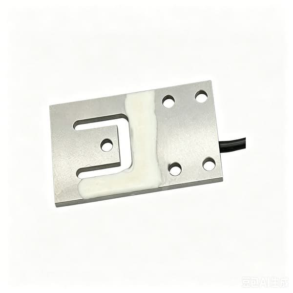
WST1101
Capacity 7.5 / 15 / 30 / 75 / 150 / 300 / 600 kg
Comprehensive error 0.05 %FS
Rated output 1.0 mV/V (7.5–75 kg)
Material anodised aluminium alloy
Protection IP65, 4-wire PVC cable
Very low profile, matched output, supplied in sets of three or four. At 7.5 kg it gives ±3.75 g, which is 37.5 % of a ±10 g budget — the capacity I would start from for an 8 kg incubator tray. At 15 kg it doubles that and stops fitting the budget.
Note: most planar beams are not corner-adjusted internally. Order a matched set and do the trimming at the junction box; a trim pot can only reduce output.
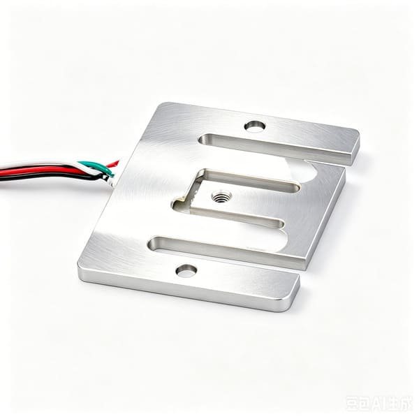
WS1102
Capacity 5 / 10 / 20 / 25 kg
Comprehensive error 0.05 %FS
Rated output 1.5±0.2 mV/V
Material anodised aluminium alloy
Protection IP65, 4-wire PVC cable
At 5 kg this is the tightest absolute accuracy we can put under a mattress tray: ±2.5 g, a quarter of the ±10 g budget. Its 1.5 mV/V output also gives more signal per gram than WST1101. Choose it when the tray is light and three cells can carry the tare plus 8 kg with margin — and check that arithmetic rather than assuming, because 3 × 5 kg is not much for a mattress assembly.
Before you standardise on it, add up tray + mattress + maximum bedding + baby, divide by three, and make sure you are not running at close to full load.
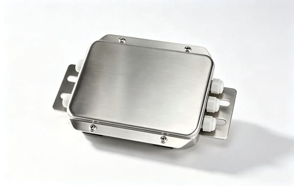
WST1513
Construction stainless steel shell, sealed entries
Channels 4, 6 or 8 (4-wire)
Dimensions 185 × 134 × 35 mm
Features low-drift trim potentiometers, surge and inductive protection on the PCB
This is where your three planar beams are summed and trimmed. In an incubator it lives in the condensation zone, which is why stainless and sealed entries matter more here than in a dry cabinet — and why I would specify a downward cable entry and a drip loop rather than a lid facing up.
A partially seated connector on a summed group does not fail loudly. It moves the zero. Use positive-locking connectors and re-zero after every tray re-insertion.

WST1508
Conversion sigma-delta, 24-bit class, 1,000,000 counts
Speed 10 or 80 conversions per second
Outputs 0–20 / 4–20 mA, 0–10 / 2–10 V
Interface isolated RS485 Modbus RTU, DC 24 V
Drives up to 12 × 350 Ω cells
For OEMs who want a weight signal in milliamps or Modbus rather than raw millivolts into their own ADC. Honest limitation: at 10–80 conversions per second this is a weight device. It is entirely adequate for an incubator readout, and it is not the part you would choose if you wanted to characterise vibration or a fast transient.
Its display resolution is stated as 1/3000. That is a metrology figure for trade instruments — for a monitoring scale you will set your own division, and you should set it fine enough to expose your own scatter rather than hide it.
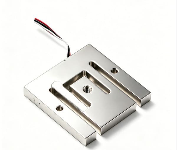
WST1104
Capacity 75 / 125 kg
Comprehensive error 0.05 %FS
Rated output 0.8±0.08 mV/V
Protection IP65, 4-wire PVC cable
This is a good planar beam and it is the same family as WST1101 — but its capacity starts at 75 kg, and 0.05 %FS of 75 kg is ±37.5 g. That is 3.75× the entire ±10 g budget of an incubator scale, before a single mechanical error is counted.
I am not recommending this for an incubator tray. It is the right part for an adult patient platform, a trolley scale, a chair scale or a bed-weighing frame — anywhere the payload is tens of kilograms to a hundred, and ±37.5 g is far below the clinical requirement. I have listed it here so that the arithmetic is on the record.
If you are designing or revising an incubator with an in-bed scale, send me the tray sketch with the weighing boundary marked, the tubing ports, the internal temperature at the cell location and your cleaning chemistry. I will come back with a capacity recommendation, a sensor set and an honest statement of what the mechanics will cost you in grams — within 12 hours. I supply the weighing core; the incubator and its regulatory file stay yours.
Or email Robin@vektorforce.com · VektorForce · www.vektorforce.com · +86 15829026027