
Load Cells for Grain Drying Towers: Weighing a Column You Cannot See
A drying tower is not a silo. In a silo the grain just sits there and the weight is an inventory figure. In a tower the grain is moving, the steel is hot, and the weight is a rate and a balance. Get those two things right and you can control drying. Get them wrong and you will spend a season arguing with farmers about shrink.
Dry-matter balance
Hot-structure zero drift
OIML R59 · NIST HB 44
1. What a Grain Drying Tower Actually Is
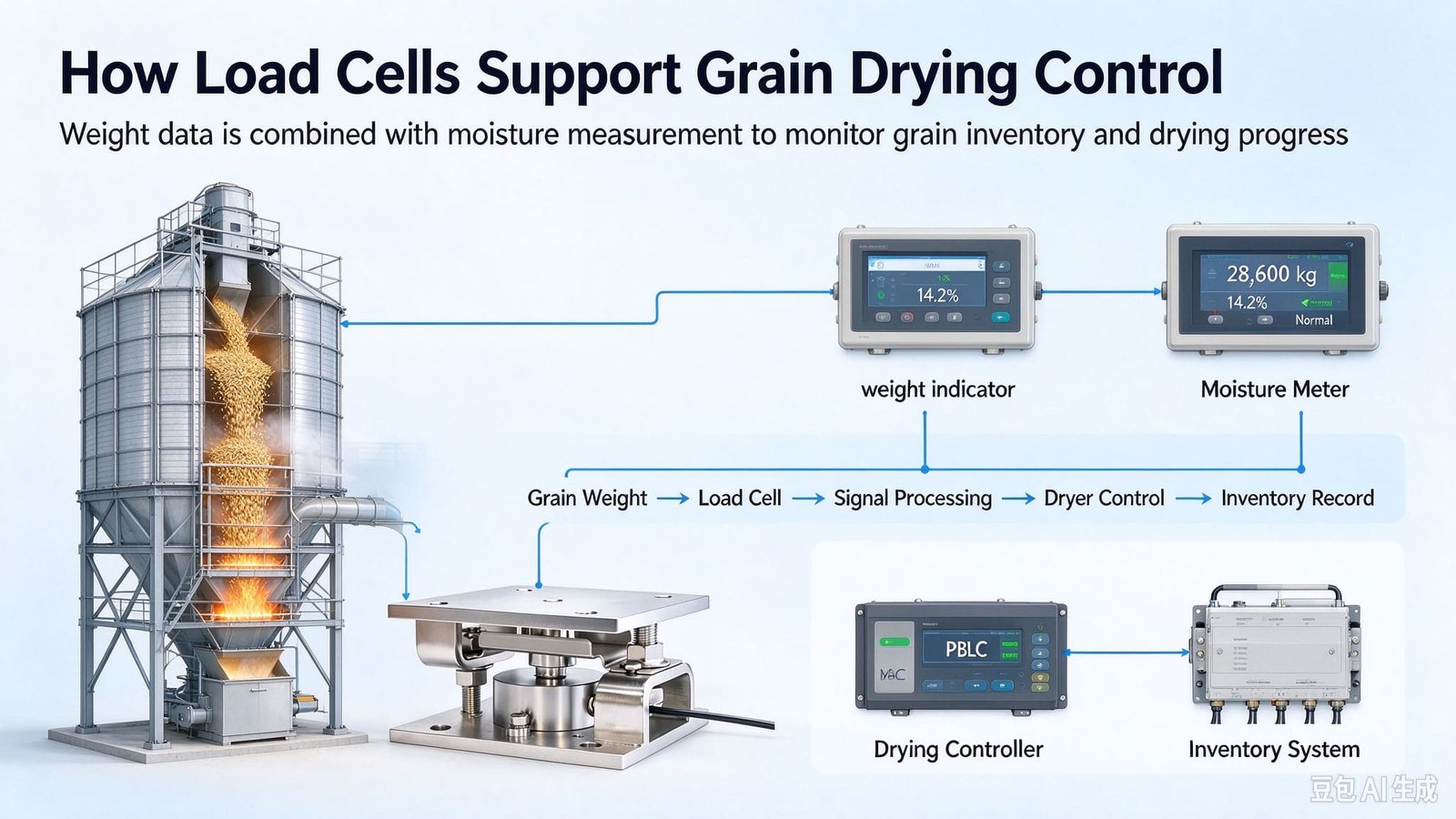
If you have never stood next to one: a tall steel box with a moving grain column inside it and hot air blown sideways through that column. Wet grain arrives at the top, falls slowly between perforated air ducts, gives up water, and leaves at the bottom cooler and drier. The machine exists to remove a specific number of moisture points at a specific rate of tonnes per hour without cracking the grain.
The numbers that matter to a weighing designer are fairly stable across builders, and they are all published on the vendor datasheets:
| Parameter | Typical value | Why a load cell designer cares |
|---|---|---|
| Tower height | 15–40 m | Thermal growth is proportional to length. This is the single biggest number in the whole problem. |
| Capacity | 10–120 t/h | Sets the mass-flow rate you are trying to resolve. |
| Hot-air temperature | 60–120 °C (up to ~160 °C on some models) | The legs and lower structure run far above ambient. You must measure it, not assume it. |
| Grain temperature at discharge | 40–60 °C | Explains a moisture-reading error that has nothing to do with your scale (see §5). |
| Grain layer thickness | 300–600 mm | This is why the hold-up mass is small compared with the steel (see §12). |
| Residence time | 30–90 min (plus 20–40 min tempering) | This is the controlled variable. Hold-up divided by throughput is the only way to know it. |
| Moisture removed per pass | 3–10 percentage points | Every point removed is about 1.16–1.18 % of the incoming mass, gone as water. |
Now the physics that makes drying expensive, because it explains why anyone bothers to weigh any of this. Turning the water inside a kernel into vapour costs about 2.26 MJ per kilogram as a thermodynamic floor, and real high-temperature towers supply far more — published figures for a working dryer sit around 4.5 to 5.5 MJ per kilogram of water removed, and the US extension figure of 2,500 Btu per pound of water works out near 5.8 MJ/kg. Call it 5 MJ/kg, and remember that fuel is the largest single operating cost on the site.
Take one tonne of wheat at 19 % moisture, dried to 15 %. Dry matter is 810 kg and it stays 810 kg. At 15 % moisture the dried mass is 810 ÷ 0.85 = 952.9 kg. So 47.1 kg of water left that tonne. At 5 MJ/kg that is 236 MJ, or about 65 kWh of heat per tonne — and if the tower runs 12 t/h for 20 hours a day through a harvest, that is roughly 15.6 MWh of heat per day. Measure the water you actually removed and you can price every point of moisture in fuel. Miss it, and you are tuning the burner by smell.
None of that is my job. My job is the part where mass becomes an electrical signal. But I have learned that if I go straight to the load cell without understanding the drying process, I end up selling the wrong class of cell to somebody who needed a flexible duct and a better zero policy. Both of those happened this year.
2. Why This Is Not Another Silo Article
We have written about tanks and silos before: the tank and silo module selection guide, the OEM integration guide for silos and feed towers, and the cement-silo retrofit using weldable strain sensors. If you are weighing a storage vessel, read those first; the selection logic there is mature and I do not want to repeat it.
A drying tower breaks three of the assumptions those articles are built on.
A silo holds hundreds of tonnes in a light shell, so the live load dominates and the tare is noise. In a tower the grain column is only 300–600 mm thick. A 12 t/h tower holds roughly 9 tonnes of grain but the empty structure can easily be 14 tonnes. Tare becomes the majority of what your cells carry.
A storage silo sees ambient plus solar. A tower’s lower sections and legs sit inside a 60–120 °C air system for weeks at a time. On a 15 m tower that is enough movement to matter mechanically, and every rigid connection is a potential load path.
Silo weighing answers “how much is in there”. Tower weighing answers “how many tonnes per hour are going through, and does the dry matter in equal the dry matter out”. That is a different measurement problem with a different accuracy budget.
There is also a safety difference, and it is the one people underestimate. A silo has a dust hazard when you fill it. A tower has a dust hazard and a continuous heat source and a recirculating air stream that carries fines into exactly the places where fines accumulate. Every dryer vendor I have visited has a story about a column-screen fire. What that means for a load cell is in §7.
3. Three Weighing Jobs, Three Different Accuracy Budgets
Here is the framework I now use on every drying-tower enquiry, and it is the reason this article exists. People say “we want to weigh the dryer” as if that were one project. It is three, and they need three different grades of hardware. The most expensive mistake in this application is buying one grade and applying it to all three.
| Job | What it decides | What accuracy actually buys you | Legal class needed |
|---|---|---|---|
| A. Hold-up cells under the tower legs |
Residence time, column-full detection, dryer control | Repeatability. You need to resolve changes against yesterday’s zero. Absolute tonnes are almost irrelevant. | None. This is process weighing. No legal metrology applies. |
| B. Wet intake and dry discharge weigh hopper / weigh bin |
Mass flow, shrink, and — if you settle on it — payment | Absolute accuracy, because these two numbers are compared with each other and with a moisture reading. | Only if it prices the grain. Then it is an instrument, and the OEM carries the approval. |
| C. Structural load share weldable strain sensors on existing legs |
Whether the legs are carrying their designed share, and whether that share is changing | Nothing absolute. You compare four legs against each other, so 1–2 % FS is plenty. | None. It is condition monitoring, not metrology. |
The trap is job B. Somebody reads a specification, sees that a legal-for-trade scale in Class III has to be marked and verified, and decides the safe thing is to buy legal-for-trade cells and use them for all three jobs. That is the worst of both worlds: you pay a certification premium on the hold-up reading, where the binding constraint is actually the mechanical repeatability of a hot structure, and you still do not get a legal instrument, because a certified load cell is not a certified scale. The approval belongs to the complete instrument, and it is granted to whoever builds it.
Ask it before you open a catalogue: does a price get calculated from this reading? If the answer is yes, you are in legal metrology territory and the whole instrument needs type approval and verification, not just the sensor. If the answer is no — residence time, level, load share, dry-matter audit — then the sensor only has to be good enough for your control loop, and buying metrology-grade accuracy is money spent on a certificate nobody will ever ask to see.
Two of the three cases in this article ended with the customer spending less than they had planned. That is not a sales technique; it is what happens when you separate the three jobs before you quote.
4. Hold-Up: The Number a Level Probe Cannot Give You
Every tower builder I have worked with controls the dryer the same way: the discharge metering rollers set how fast the column descends, and the PLC runs a control loop on roller speed against the discharge moisture reading. Run the rollers faster and grain spends less time in the hot zone; run them slower and it spends more. Residence time is the drying recipe.
And residence time is not something you can measure directly. It is defined by two other numbers:
hold-up (t) = throughput (t/h) × residence time (h)
You already know throughput from the metering rollers’ calibration, and you already have a moisture reading. The missing term is the one nobody measures: how many tonnes of grain are inside the tower right now.
Published ranges put a tower’s hold-up somewhere between roughly 5 and 180 tonnes: a small 10 t/h tower with a 30-minute pass holds about 5 t, and a 120 t/h industrial tower at 90 minutes holds about 180 t. That is a very wide range, and it is wide because the grain layer inside is only 300–600 mm thick — a tower holds far less grain than its silhouette suggests.
Why a level probe is not enough
Towers almost always have level probes in the wet bin, and they are there for a good reason. If the grain columns run partially empty, the drying air stops pushing through the grain and finds the empty path instead — the bed short-circuits, the air bypasses, and drying collapses in the section that is still full. So the probes start and stop the elevator to keep the columns topped up.
A level probe is a switch at one height. It knows “topped up” or “not topped up”. It cannot tell you how much is in there, it cannot tell you how fast the level is falling, and it cannot tell you that grain stopped moving. A load cell system can tell you all three, from one continuous number:
- Residence time in real time. Divide hold-up by the actual discharge rate and you have minutes of dwell, continuously, instead of a figure you infer from a roller calibration you last checked two seasons ago.
- Column-full detection that actually holds. Instead of a switch, you get a margin: “we are 380 kg below the level where short-circuiting starts”.
- Bridging detection. If the discharge runs and the hold-up does not fall, the grain is arching and the rollers are pulling from a void. That failure is invisible to a level probe and expensive to discover at the moisture meter.
How much resolution do you actually need?
This is where the money is saved, so let us do it properly. Take a 12 t/h tower with a 45-minute pass. Hold-up is 12 × 0.75 = 9 tonnes. Say the process engineer wants residence time held to ±5 %, which most would call generous. Five percent of 9 t is 450 kg. That is the resolution the control loop needs.
Now compare it with what a well-installed module system delivers. A 0.15 % repeatability against hold-up on 9 t is 13.5 kg — roughly thirty times more resolution than the process needs. Which means the specification question was never which accuracy class of load cell. It was how to keep the reading repeatable on a structure that is moving and heating. Those are two different questions, and only one of them is about the sensor.
A hold-up reading from under-the-leg load cells is not a certified mass. It includes every ladder, platform, duct support and cable tray bolted to the weighed structure, and it shifts with temperature. Use it as a delta against a defined cold, empty reference — never as an inventory figure you would quote to an auditor. If you need a defensible tonnage, it belongs in a weigh bin or on a weighbridge, not in the tower’s own legs.
5. The Dry-Matter Balance: Your Free Audit Instrument
Drying removes water and almost nothing else. The kernel’s dry matter goes in and comes out, and it has to balance. That gives you a check that costs nothing once you are already weighing both ends of the tower, and it is the single most useful thing I have ever shown a dryer operator.
min × (1 − Mi) = mout × (1 − Mo)
Rearranged for the number you do not trust: Mo = 1 − (1 − Mi) × min ÷ mout. Two weights, one inlet moisture, and you have an independent estimate of the outlet moisture.
The useful question is not whether it works — it is how well. If your weights carry an error, that error lands in the moisture figure you calculate, and the sensitivity deserves writing down.
Worked from first principles at 25 % inlet moisture and 15 % outlet, that relationship comes out at a factor of about 0.96. In plain terms: if you want to audit your moisture measurement to a tenth of a point, your weighing has to be good to a tenth of a percent. On a 3 t weigh hopper that is 3 kg. On a 30 t weigh bin it is 30 kg. Both are entirely achievable with a well-installed weighing module; neither is achievable if the hopper has a rigid take-away conveyor bolted across it.
What you are auditing, and why it needs auditing
Grain moisture meters are good instruments used in a difficult place. The US extension services have documented the failure mode for decades: a meter measuring grain straight out of a high-temperature dryer reads low, because the kernel’s interior has not equilibrated with its surface. The published figure is that the reading may be about 2 percentage points lower than true moisture, with the error growing as inlet moisture rises. Above 25 % incoming moisture, readings should be treated as estimates. Meters also misbehave on cold grain — below roughly 40 °F (about 4 °C) they are simply not accurate, and the sample has to be warmed in a sealed container first.
Legally, moisture meters are instruments in their own right, separate from the scale. In the United States they sit under NIST Handbook 44 §5.56 (Grain Moisture Meters), with near-infrared analysers under §5.57 and type evaluation through NCWM NTEP Publication 14. Internationally the reference is OIML R59:2016, Moisture Meters for Cereal Grain and Oilseeds, approved at the 51st CIML meeting in October 2016 with China and the United States as co-secretariats; OIML R146 covers protein instruments. Two clauses in R59 are worth knowing:
R59 applies to instruments measuring a fixed representative-size grain sample. It explicitly does not apply to devices measuring moisture in motion. There is therefore no legal basis for an in-line moisture reading on the discharge spout as a settlement figure — the sample has to be taken and measured off the line.
R59 also notes that drying methods are not specifically covered, though they may qualify if they perform to the recommendation’s requirements. That is the door through which a mass-balance method could be argued — and the reason the accuracy of your weighing matters.
Now the commercial version of the same point. One percentage point of moisture at a 15 % final target is 1.176 % of the mass — the shrink factor, 100 ÷ (100 − 15). At €210 per tonne that is €2.47 per tonne for every point. A systematic half-point error on 20,000 tonnes a year is about €24,700 a year, moving in one direction, year after year, invisible because nobody cross-checks. That is the number to put in front of whoever holds the budget for a proper weigh hopper.
6. The Hot Tower Problem: It Is Never the Sensor
This is the part of the application that catches out experienced weighing engineers, because the instinct is to blame the load cell’s temperature coefficient, and the temperature coefficient is almost never the culprit.
Run the numbers. Our standard hopper-scale modules are specified at ±0.02 %FS per 10 °C on the effect of temperature on zero. On a 10 t module that is 2 kg per 10 °C. Give the tower a generous 50 °C swing between a cold morning start and a hot afternoon run, and the cell itself contributes about 10 kg. Against a 9-tonne hold-up, that is 0.11 %. Annoying, correctable, not the problem.
The structure is the problem. Steel expands by about 12 × 10−6 per °C. Take a 12 m section of tower that goes from 10 °C at dawn to 60 °C in the afternoon — which is entirely normal in a tower that is drying — and it grows:
Seven millimetres of movement on a structure that somebody bolted to a duct, a burner frame and a discharge section. Those members cannot absorb 7 mm of interference elastically — the forces required are far beyond what they can carry — so they take it up in bending, buckling and local yielding, and the share of the tower’s weight that reaches your load cells becomes a function of how stiff each accidental path happens to be today. You cannot factor that out. You can only remove it.
There is a second effect that gets less attention than it deserves: the horizontal dimension. A tower’s hot zone grows radially as well as vertically, and if the legs are anchored to a stiff concrete plinth with no allowance for that, the growth arrives at the footings as a lateral force. That is a job for stay rods and slotted connections, not for the sensor.
The two tests that settle it in an afternoon
Test one: empty the tower, take the zero, start the burner and the fans, and log the reading for two hours with nothing going in or out. Nothing is moving, so nothing in the reading should change except the cell’s own drift. If the zero walks by hundreds of kilograms, the movement is mechanical and thermal, and no load cell will fix it.
Test two: a three-point zero — cold and empty in the morning, warm and empty a few hours later, hot and empty at the end of a run — logged beside leg temperature. You will usually find a repeatable curve. A repeatable curve can be subtracted; an unrepeatable one means you still have parallel load paths to remove.
One specification to check before you order, because it catches people out: our modules are compensated over −20 to +65 °C. If the section of leg where you intend to mount them runs hotter than that — and on a tower with a poorly shielded lower plenum it can — say so at enquiry. It changes the compensation we build in and the cable we supply, and it is much cheaper to raise it in the enquiry than to discover it in the harvest.
7. Dust, Fire, and the Zone Your Cells Sit In
Grain dust is a genuine explosive dust, and anybody specifying equipment for a dryer or an elevator should have the numbers in their head. The reference values used in the industry, drawn from the NFPA tables for combustible dusts, look like this:
| Dust | Kst bar·m/s |
MIE mJ |
MEC g/m³ |
Pmax bar |
Cloud ignition °C |
|---|---|---|---|---|---|
| Wheat | 82 | 60 | 55 | 7.1 | 480 |
| Corn | 137 | 40 | 45 | 6.6 | 400 |
| Rice | 82 | 40 | 45 | 6.4 | 440 |
Three things in that table matter more than the rest. Grain dusts generally land in the 50–200 bar·m/s band with peak pressures of 5–10 bar, and a grain dust explosion can reach about 8 bar — ten to twelve times the mechanical resistance of typical process equipment. Layer ignition temperatures are far lower than cloud ignition temperatures, commonly 200–300 °C, which is why smouldering nests and hot surfaces cause more events than open flames. And minimum ignition energies in the tens of millijoules are within reach of ordinary static from an ungrounded person or a plastic duct.
Dust layers deserve their own sentence, because a dryer makes them. A layer half a millimetre thick across a silo roof holds enough fuel to destroy the structure, and disturbing a 0.5 mm layer inside a 10 m vessel can create a cloud fifty to a hundred times the minimum explosible concentration. In equipment language: every ledge, duct support bracket and cable tray on your tower is a place where a layer forms, and the load cell cable runs along several of them.
I supply load cells, weighing modules, junction boxes and indicators. I do not supply the zone classification of your plant, the explosion protection document, or the Ex assessment of the installation. Those belong to the site operator and to whoever builds the dryer. What I can do is tell you honestly which housings and cable options suit each position: IP68 where there is wash-down or a wet gutter, stainless junction boxes with sealing glands, armoured or high-temperature cable — and the fact that the reference values above must be replaced by site-specific testing. The relevant ASTM methods are E1226 (explosibility), E1515 (minimum explosible concentration), E2019 (minimum ignition energy), E1491 (cloud autoignition) and E2021 (layer ignition).
One practical point from the same table. A load cell is a passive resistive bridge, and its body is normally bonded to the structure through its mounting bolts — which is what you want. But stainless housings on insulating shims, or a painted and galvanised leg used as the only earth path, can leave the housing floating. Check the bonding resistance rather than assuming it: industry practice for a permanent bond is well under 10 Ω, and on this kind of equipment I would rather see it below 1 Ω.
And the positioning rule that follows from all of it: mount the weigh modules on the legs, below the hot zone, where the temperature is stable and the dust is falling away rather than settling. If a leg is not hot, you have bought yourself a much easier project.
8. Legs, Modules, and the Load Paths Nobody Counts
Every drying-tower enquiry arrives as a load cell question. Ten minutes later it has turned into a load path question. I have never once been asked about a load path in the first email, and every drifting, “the scale is lying” project I have worked on has ended in one.
Here is why. A tower is a hyperstatic frame. It has four or more legs — and it also has a hot-air duct, an exhaust stack, a catwalk, a ladder, a cable tray, a pneumatic line, an electrical conduit and a spouting to the next bin. Each of those has two ends, and one end is on the tower. If the other end lands on a different foundation and the connection is rigid, you have built a second load path around your load cells. It will not break anything. It will simply make your weight wrong, by an amount that changes with the weather and the burner setting.
| What is bolted to the tower | What it is really doing | What it costs your reading |
|---|---|---|
| Hot-air duct from plenum or burner | Several metres of steel growing 5–8 mm between cold and hot | The biggest single error source on the machine. Case 1 below is exactly this. |
| Exhaust stack and cyclone | Usually braced to the tower; wind pressure changes the draught | A slowly varying bias, worst on windy days |
| Catwalk, ladder, handrail | Bolted to the tower and to a neighbouring structure | A permanent shunt — and someone will add to it next season |
| Pneumatic line / spouting | Rigid pipe run to the next bin, anchored at both ends | Thermal plus pneumatic reaction forces |
| Cable tray and conduit | Steel, anchored at both ends, never in the drawing | Small, and always forgotten |
Everything that touches the tower between the cell plane and the sky is either flexible or counted. There is no third option. A rigid connection you have not counted is the same thing as a weighing error you have not measured, and it will find you in the first week the weather changes.
How many legs, and how big a module
For a storage vessel the module suppliers publish rough proportions, and they are a reasonable starting point: 4–6 t of product gets 4 legs and 3 t modules, 8–10 t gets 6 legs and 3 t modules, 15–20 t gets 8 legs and 5 t modules. Read the pattern rather than the numbers — they are written around the contents, giving roughly twice the installed capacity as margin, and they say nothing about the steel you are also lifting.
For a dryer you have to add the structure explicitly, and this is where §2 bites. On a mid-size tower the empty steel is the bigger half of the total. My working formula is deliberately dull:
Bolt two of them and float the other two
This one comes out of our own production rather than a catalogue, and it is worth more than most of the accessories you will be quoted for. When several cells work as a set, do not fix the load end of every cell rigidly. If all four are bolted solid to a frame that is itself bolted solid to a foundation that is not perfectly flat, you have built a hyperstatic set, and from then on the frame’s stiffness decides how the load is shared — not the cells. Make two fixed and two floating on a sliding plate or a spherical seat: the fixed pair locates the structure, the floating pair only ever sees vertical load.
The set still needs lateral restraint, but that restraint belongs on a separate mechanical stop, not on the cell body. And a warning that goes with it: in any multi-cell set, side or transverse forces do not cancel. A pipe that pulls sideways on one module shifts that module’s reading and leaves the other three alone, so the error lands straight in your total instead of quietly averaging out.
Do not let your cells become the wind brace
A 25 m tower presents 60–100 m2 of face to the wind. In a 100 km/h gust that is tens of kilonewtons of horizontal force and a base overturning moment of several hundred kilonewton-metres, and it reverses direction. Design the lateral restraint so the cells see none of it — four bumpers or a base tie carrying the horizontal load is a cheap afternoon. Discovering it after your sensors have been the tower’s brace for a season is not.
Do this before you choose a model number. It takes twenty minutes and it has saved me two warranty seasons.
- Name every item above the cell plane that touches the tower. Walk it, do not read the drawing.
- For each one, find where the other end lands. Same foundation — probably fine. Different foundation — flexible joint, or a force you have to count.
- Ask what each of those forces does when the burner has been running for eight hours.
If your tower sits inside a feed mill, the same reasoning applies one machine further down the line — the wagon and mixer side of it is covered in our TMR feed mixer wagon notes.
9. Case: A Hold-Up Reading That Moved 280 kg Every Afternoon
Wielkopolska, Poland, spring 2025. A dryer builder I had supplied two seasons earlier called me with a warranty claim, which is my least favourite kind of call and the most useful kind of project. Their 22 m tower, 14 t/h, four legs, was standing on four of our column modules. The complaint was specific and, I thought, fair: “In the morning the column is 9.5 tonnes. By four in the afternoon it is 9.8. Nothing changed. Your sensor is drifting.”
280 kg on a 9.5 t hold-up is 2.9 %. That is far too big to be a load cell problem and far too small to be a safety problem, which is the signature of a mechanical one. So the first thing I asked for was not a drawing. It was the zero log — how and when the operator re-zeroed the tower.
There was no log. There was a habit: the shift supervisor pressed ZERO at the start of every shift, because that is what you do on a hopper scale. Which meant the tower was re-zeroed once in the cold morning, once in the hot afternoon and once at night, each time subtracting a different amount of thermal load and hiding it. The drift was not a drift at all. It was the difference between three zeroes.
With the numbers written down we found the source. The hot-air duct between the plenum and the burner was hard-bolted to the tower on a diagonal, with no expansion joint on the tower side. That run is about 6 m of steel, and it sees roughly 90 K between a cold start at 15 °C and a running temperature at 105 °C:
Steel expands at about 12 × 10−6 per kelvin. Over 6,000 mm and 90 K that is 6.5 mm of movement. Routed through the diagonal brace, that displacement had an effective vertical stiffness of roughly 0.4 kN/mm, which puts about 2.7 kN — call it 280 kg — into the tower structure.
Now notice the two ways to read that number. Spread across four modules it is 0.7 % of one module’s 100 kN, invisible. Against the hold-up signal it is 2.9 %, which is the entire measurement. The same force is negligible to your hardware and fatal to your process. That is why nobody finds it by looking at the sensor.
And it was not only the reading that suffered. Their control band was “keep hold-up between 9.0 and 9.8 t”, and they were reading a number that wandered 280 kg on its own. The afternoon of the complaint, the operator saw the hold-up rise, concluded the discharge was starving, and opened the gate. That pulled 400 kg out of the column, and at 14 t/h a 400 kg cut is 1.7 minutes off a 40.7-minute residence time, or about 4 %. On a tower taking six moisture points out per pass, four percent less drying time is roughly a quarter of a point of moisture — enough to push a 15.0 % contract limit to 15.3 % and start an argument at the weighbridge.
So the sensor was being blamed for a chain that started in a duct and ended in a rejection. Three things fixed it, and only one of them was mechanical:
- A stainless bellows expansion joint between the duct and the tower, with the duct anchored only at the burner end.
- A written zero policy: zero only when the structure is cold and stable — burner off for two hours and ambient changing less than 2 K/h — and never mid-shift, whatever the shift supervisor prefers.
- A temperature channel logged beside the weight, so the next person who sees a slow afternoon rise can compare it with the frame temperature instead of reaching for the zero button.
We load-tested the four modules anyway: repeatability of 0.1 %, all four fine, and I sold nothing on that trip. The afternoon walk went from 280 kg to under 20 kg, which on a 9.5 t hold-up at 14 t/h is about five seconds of residence time — inside the noise of everything else on the site. When the tower came down for its annual service I asked for the zero log. They had one. That was the deliverable I cared about.
10. Case: The 3.4-Tonne Shrink Argument
Bács-Kiskun, Hungary, autumn 2025. A co-operative drying maize was losing an argument with its farmers every single day. The growers were paid on moisture, the co-op measured the moisture, and both sides kept arriving at dry weights about 3.4 t apart on a 150 t/day intake. Accusations had begun, which is a bad place for a trade to get to.
They asked me for a better scale. Before quoting one I did the dry-matter balance, because it is free, and because it tells you which of the three numbers in the chain is weak. On a 150 t intake at 24 % dried to 14 %, the dry matter is fixed and the output mass follows:
| What changes | Dry matter in | Predicted dry output | Shift per day |
|---|---|---|---|
| Baseline: 24.0 % in, 14.0 % out | 114.0 t | 132.6 t | — |
| Intake meter reads 1 point high (25 %) | 112.5 t | 130.8 t | −1.7 t |
| Discharge meter reads 1 point high (15 %) | 114.0 t | 134.1 t | +1.6 t |
| Both, in opposite directions | 112.5 t | 134.1 t | 3.3 t |
One point of disagreement on each moisture reading reproduces the entire 3.4 t dispute — and one point is inside the tolerance of two moisture meters that are both perfectly in specification. Nobody was cheating. The argument was metrological, and it was going to be settled by whoever had the better sampling procedure, not by whoever bought a better load cell.
What we actually changed was less dramatic than a new scale, and it is the part I would repeat on any site like this:
- A new wet-intake weigh hopper on four shear-beam modules, replacing a belt scale that had been drifting all season — because mass flow needs a static sum, not a belt.
- WST1502 indicators on isolated RS-485 for both the intake and the discharge, so the two masses, the moisture values and the timestamps land in one dataset. Half the value of the audit is just having the numbers on the same clock.
- A multi-channel junction box per weigh hopper, so the four modules sum inside one instrument. That is easy to miss: if the intake mass and the discharge mass share one A/D, one excitation and one calibration chain, their errors are correlated and cancel in the difference. On two unrelated instruments they add instead.
- An actual moisture procedure: samples cooled to ambient before a capacitance reading, and a reference-oven check on three samples a day.
Over the next six weeks the balance closed to within ±0.4 t/day and the daily argument disappeared. But the audit also caught something real, which is why I now push this on every drying enquiry. The balance ran consistently short on windy days — roughly 0.9 t on days averaging over 5 m/s. We hung a collection box on the cyclone outlet for three days and emptied it: fines. Dry matter was leaving the tower through the stack, not through the dryer. Fixing the cyclone is the cyclone vendor’s job, not mine, but if you sell drying by weight you should know that some of your shrink goes out of the air.
11. Case: A Tower Nobody Was Allowed to Cut
Beheira, Egypt, summer 2025. A storage and drying operator wanted a weighing system installed before harvest, three weeks away. The tower’s four legs were encased in a concrete plinth up to 900 mm, and nobody was going to cut, jack or re-grout anything with the season starting. There was no space anywhere under the structure for a load cell module.
So I told them something a supplier is not supposed to tell a customer holding a budget: you cannot have a weighing system this year, and I am not going to sell you one that pretends to be. What they could have, in ten days and with no cutting, was a leg load-share and overload-warning system built on four weldable strain sensors bonded to the legs just above the plinth — and it turned out to be the more useful instrument anyway.
Why a strain sensor is not a scale, in one calculation
Their leg is a 150 × 150 × 6 mm square hollow section, so the steel area is about 3,456 mm2, and the working load per leg is roughly 61.5 kN. That gives a stress of 17.8 N/mm2 and a strain of about 85 µε on a 300–1,000 µε sensor. The sensitivity is straightforward:
1 µε with E = 210,000 N/mm2 and A = 3,456 mm2 is 210,000 × 10−6 × 3,456 = 726 N, so roughly 0.73 kN or 74 kg per microstrain.
A weldable strain sensor quoted at 1–2 % of a 1,000 µε range therefore carries 10–20 µε of uncertainty — which is 7–15 kN, or 0.7 to 1.5 tonnes per leg. On a leg carrying 6.3 tonnes, you cannot see a small imbalance. You can see a gross one. For a scale that is a disqualifying number; for a load-share check it is completely adequate, and saying so plainly is the whole job.
The trick that makes it genuinely useful is that you do not need the absolute tonnes at all. If the four legs are identical sections, then load share = εi ÷ Σε, and the area and the modulus cancel out completely. The one number that matters — how the weight is divided between the four legs — needs no material assumption, no calibration mass and no jacking.
Two months later the call came, and it was the case for the whole exercise. Their freshly rebuilt discharge hopper had changed the frame’s geometry, the discharge gate had started binding on one side, and they had replaced the actuator twice without curing it. The strain data said the frame was twisted: leg 3 was carrying 34 % of the load where it should carry 25 %. The cause was a 3 mm packer plate left under leg 3’s base plate when the plinth was re-grouted. Raising that corner made it stiffer, so it took more of the load and the opposite corner unloaded. Removing it and re-shimming brought the four legs back to 24–26 %. The binding gate, the replaced actuators and a moisture spread of 0.3–0.5 of a point across the discharge — which the operator had been attributing to the burner — all came back into line.
Three practical notes, because I would rather you hear them from me than discover them:
- Mount all four identically — same face, same height above the plinth, same weld procedure. If a leg is bending, the strain around the section is not uniform, and a sensor on a different face is measuring a different thing.
- Baseline, not calibration. You cannot re-calibrate a bonded strain sensor in place. Record a cold, empty reference and compare everything against it, with a temperature channel alongside so you can separate structural movement from load change.
- Get the temperature into the conversation early. The plinth-level legs measured 46–52 °C in service, comfortably inside the sensors’ rated band. Had that number come back at 75 °C the honest answer would have been no. I would rather lose the order on day one than argue about it in October.
Welding on a live grain structure is a hot-work job, and it belongs to their safety people, not to me: the area was vacuumed and the dust layer removed before anyone struck an arc, and the work was done inside a 36-hour shutdown on a permit. That is the dust hazard from §7 arriving as a paperwork problem rather than a design one, which is how it usually arrives.
I sold them four weldable strain sensors, one junction box and two days of commissioning. When they rebuild the tower in a few years, they will be able to put real modules under it and have a real scale — and they know exactly who to call, because I was the one who told them to wait.
12. The Selection Worksheet
This is the order in which I actually do it, which is not the order in which the catalogue is arranged. Nine steps, and the first four have nothing to do with a load cell.
- Get the empty structure weight. From the builder’s drawing, and check it against a jack reading if you can. On a tower this is well over half the total load, so an error here is an error everywhere.
- Work out the design hold-up mass. Throughput times residence time is the fastest route: 12 t/h at 45 minutes is 9 tonnes. If you prefer volume, multiply the packed column volume by bulk density — wheat about 0.78 t/m3, maize 0.72, rapeseed 0.68, barley 0.62, paddy 0.58 — and remember the column is only 300–600 mm thick. Add the discharge hopper accumulation if that hopper sits on the weighed structure; it is the number everyone forgets.
- Divide by the leg count and apply the dynamic factor. Use k = 1.1–1.2. Not 1.0; the column moves and the gate slams.
- Choose the module so the working load sits at 30–70 % of capacity. Prefer the smaller rating that still clears 70 %, because a smaller rating applies less absolute error to the grain you are trying to measure.
- Measure the temperature at the mounting point. Our standard module family is compensated from −20 to +65 °C. Measure the leg in service, and if you can, across a whole season rather than on the day I visit.
- Settle the dust zone and the ingress rating before the first wash-down, not after.
- Ask the legal question from §3 and write the answer down. A one-line decision recorded now saves a very expensive conversation later.
- Write the zero policy. When zeroing is allowed, who may do it, and what the structure has to look like at that moment. Case 1 in this article is a zero policy, not a sensor.
Run against a mid-size tower, it looks like this:
| Step | Value | Where it comes from |
|---|---|---|
| Empty structure | 14.5 t = 142 kN | Builder’s drawing |
| Hold-up, 12 t/h at 45 min residence | 9.0 t = 88 kN | Throughput × residence |
| Discharge hopper accumulation | 0.8 t = 7.8 kN | Hopper volume × bulk density |
| Total static | 24.3 t = 238 kN | Sum of the three above |
| Per leg, four legs | 59.6 kN | 238 ÷ 4 |
| With k = 1.15 | 68.5 kN | 59.6 × 1.15 |
| Module chosen | WST809 at 100 kN → 68 % | Inside the 30–70 % band |
| Softer alternative | WST802 at 200 kN → 34 % | More shock headroom, coarser resolution |
| Error floor from the modules | ±5 kg per leg, ±10 kg on the sum | 0.05 % FS at 68 % utilisation |
Look at that last row against the hold-up. A four-leg sum carries roughly 10 kg of sensor error on a 9 t hold-up — 0.11 %. Once you have done that calculation you know something useful: the hardware is no longer your problem, and everything you spend from here belongs on load paths, temperature and a written zero policy. That is the argument I use when a customer wants a more expensive cell instead of fixing a duct.
A 24-tonne tower needs 24 tonnes of test weights, which nobody has. There are two honest routes and I have used both. Route A — calibrate the modules, then sum them. Load each module on a press before installation, record its certificate, and install it in the position it was calibrated for. This is what I do for towers, because it is reproducible and it needs no grain. Route B — material substitution. Fill the tower with weighed-in grain, using a verified intake scale as the transfer standard. This is standard practice for large scales: OIML R76 allows material to be substituted for weights where a weight stack is impractical, and NIST Handbook 44 handles bulk weighing systems largely through material tests. It is slower and it ties up the plant, but it validates the whole load path in one go, which Route A does not. If you only ever do one, do this one at the end of the first season.
13. What I Supply, and What I Do Not
I am a weighing component supplier. I am not a dryer builder and I am not a system integrator, and the fastest way to lose your trust is to let you find that out after the purchase order. So here is the line, drawn where it actually sits.
- Load cells, weighing modules and matched sets
- Weldable strain sensors for retrofit and load-share work
- Multi-channel junction boxes and the trim procedure for a set
- Weighing indicators: summing, taring and RS-485 Modbus RTU output
- Cable specification, gland orientation and routing rules
- A written review of your load path, if you send me the drawings
- The zero policy in writing, with the temperature conditions spelled out
- Module selection arithmetic, shown so you can check it
- Calibration guidance and the certificate for each module
- The dryer itself: the tower, the ducts, the burner, the plenum
- The drying control loop, moisture strategy or recipe handling
- Moisture meters, sampling equipment or the reference oven
- Type approval, verification or any legal-for-trade certification. That approval belongs to the complete instrument and to whoever builds it.
- Dust-explosion protection engineering: zone classification, venting design, ignition-source assessment
- Structural design of the tower, the plinth, the wind restraint or the catwalk
- Hot-work permits, gas testing or the cleaning before anyone strikes an arc
- Cyclone or aspiration performance. When dry matter leaves through the stack in §10, that is a separation problem, not a weighing one.
Where the two lists meet is where most drying-tower projects go wrong, so I will say it plainly: a load cell can only measure what actually arrives at its axis. It cannot know about the duct that grew, the packer left under a leg, the cyclone throwing your lightest fraction over the fence, or the operator who re-zeroed at lunchtime. Those four things decided the three cases above, and every one of them was outside the sensor.
- Our standard module family is compensated to +65 °C. Not 120 °C. That is a real constraint on a dryer, which is why step 5 of the worksheet says measure the leg. Above that band we are into standoffs, relocation or a special.
- The WST1502 indicator lives in a cabinet. Its operating range is 0–40 °C. It will happily sum your four modules and log to your PLC, but it will not survive a Polish January or an Egyptian August outdoors.
- A weldable strain sensor needs a leg that is actually strained. A heavily over-built leg at 20 % of its allowable stress gives a small signal, and small signals plus 1–2 % FS do not make a good load-share check. Send me the section and the working load and I will say whether it is worth bonding anything.
- Our ingress ratings are not all the same. WST807 is IP68, WST802 and WST703 are IP65, and the WST809 datasheet states no figure at all. If you need it for a specification document, ask and I will get it in writing from the factory rather than let you find a gap.
14. Questions I Get Every Season
How many load cells does a grain drying tower need?
One per leg, and towers have four to eight, so follow the leg count rather than picking a number you like. Three cells under a four-leg tower is not a weighing system — it is a mechanism that will share load unpredictably. Every module in a set also needs the same capacity and the same matched batch, because any mismatch lands straight in the total.
Can I use weldable strain sensors instead of load cells for weighing?
You can measure load share and structural condition, but not weight to any useful resolution. A 1–2 % FS weldable sensor on a leg carrying 6 t works out to roughly 0.7 to 1.5 t of uncertainty, so it catches a gross imbalance and misses a small one. What it does really well is the ratio between the four legs, because the section area and the elastic modulus cancel out and no calibration mass is needed.
What accuracy can I expect from a drying tower weighing system?
Think in repeatability, not absolute accuracy, because hold-up is a trend against yesterday’s zero. The module floor is small: a 0.05 % FS module at 68 % utilisation contributes about 5 kg per leg, roughly 10 kg on a four-leg sum, which is 0.11 % of a 9 t hold-up. Thermal and load-path effects are ten to fifty times larger, so that is where the effort belongs. If you need absolute tonnes for payment, use a weigh hopper where the cell sees a clean vertical load.
Does a grain dryer scale have to be legal for trade?
Only if a price is calculated from the reading. Holding a control band, measuring residence time and detecting a full column are process measurements and no legal metrology applies. If the reading prices grain, the complete instrument needs type approval and verification — and a certified OIML R60 load cell does not make an uncertified scale legal for trade. That approval belongs to the instrument and to whoever builds it.
Why does my dryer weight reading drift during the afternoon?
It is almost always thermal, and almost always the duct. Steel grows about 6.5 mm over a 6 m run at 90 K, and if that duct is hard-bolted to the tower with its other end on a different foundation, the growth arrives as a force of a couple of hundred kilograms. Then look at the zero policy: an operator who re-zeroes every shift subtracts a different thermal load each time, turning a repeatable effect into an apparent random walk.
What IP rating do I need for a grain dryer tower load cell?
Gland the junction box rather than chase another IP digit on the cell. A stainless multi-channel box with its cable entries facing down and away from the dust fall does more for reliability than any single rating. IP65 modules are normal here; IP68 is the answer if the area gets hosed down. Put the electrical assessment on the enclosure and the wiring too — the cell is a passive bridge dissipating a fraction of a watt, while the cable, the glands and the box are where the real risk sits.
How do I calibrate a scale on a tower I cannot hang test weights on?
Two honest routes. Calibrate each module on a press before installation and sum them — quick and reproducible, but it does not validate the load path. Or use material substitution, filling the tower with weighed-in grain against a verified intake scale as the transfer standard. The second is standard practice for large scales: OIML R76 allows material in place of weights where a weight stack is impractical, and NIST Handbook 44 handles bulk systems largely through material tests. Whichever you choose, record the empty tare and the date it was taken.
What temperature do the load cells have to survive on a grain dryer?
Measure the leg at the mounting point, and do not estimate it from the duct temperature. Hot air runs 60 to 120 °C and the structure near the plenum is genuinely hot, but the legs are usually well below that: the tower in case 3 measured 46 to 52 °C at plinth level. Our standard family is compensated from −20 to +65 °C, so the question is simply whether your leg stays inside that band. If it runs hotter, that is a custom enquiry and not a catalogue order.
The Parts I Would Quote for a Grain Drying Tower
Six parts covering the three jobs in §3, plus one that is not on the website yet and gets its own note below.
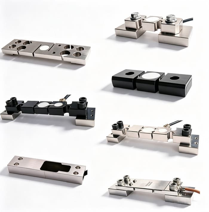


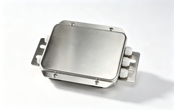

If your leg load takes you past what the WST809 covers — a big tower, or one where the discharge hopper sits on the weighed frame — the answer is the WST1801, our high-capacity column weighing module. It is the first thing I look at for a heavy tower leg, and I am not going to dress it up: there is no product page for it yet, so there is no link above and I have not put it in the grid.
That is a deliberate choice rather than a hole in the article. I would rather write to you and say “here is the drawing, here is the rated load and here is the matched-set data” than point you at a page that does not exist. Ask me for WST1801 and you will get the datasheet by email the same day.
If the weight data then has to travel — into a PLC, a dryer control system, an ERP or a silo management package — the OEM integration guide for smart warehouse systems covers the logging and interface side in more detail than I can here. And if your problem is really a storage vessel rather than a dryer, the tank and silo module selection guide is the place to start.
Give me the empty structure weight, the leg count and section, the throughput and the residence time, and the temperature at the mounting point. I will come back with the module sizing, the leg-count arithmetic and the written zero policy — and if the honest answer is that you should instrument the legs instead of weighing the tower, that is what you will get.
Request a specification →
Or email Robin directly