
A crane overload limiter is allowed to be sloppy, but it is not allowed to drift or die.
A crane overload limiter is allowed to be sloppy. It is not allowed to drift, and it is not allowed to die. Those are two completely different specifications, and almost every inquiry I receive about a load cell for hoisting machinery is written for the first one.
28 October 2026
12 min read
GB 12602 · EN 13001-2 · EN 13155 · ASME B30
- Why the first question I get asked is the wrong one
- What “hoisting machinery” covers, and where a load cell is allowed to sit
- What I supply, and what I do not
- Five sensor forms, and how the mounting position picks one for you
- Project 1 — Tower crane OEM in the Gulf: the pin that had nowhere to stop turning
- Project 2 — A steel service centre that asked for 0.05 % on an overload limiter
- Project 3 — An electric chain hoist distributor who was measuring the wrong force
- The three trip points that actually decide the specification
- Error budget: a 5 % system tolerance does not mean you can relax
- Where the sensor sits changes the number by a factor of four
- Proof load, in-situ calibration, and who signs the certificate
- Seven mistakes I see repeated, and the 7-step path I use now
- Who owns what: a standards map for hoisting machinery
- Where the weighing core ends
- Load cells for hoisting machinery: the seven parts I actually quote
- Frequently asked questions
1. Why the first question I get asked is the wrong one
Nine out of ten hoisting inquiries open the same way: “What accuracy can you give me on the load cell?”
It is a reasonable question. It is also, on this particular application, almost irrelevant. Here is the arithmetic that made me stop answering it first.
The Chinese national standard that governs crane overload protection devices, GB 12602-2009, asks for a display accuracy better than 5 % of full scale and an action error better than 3 % of full scale. The standard itself notes that because the system tolerance is only about ±5 %, a transducer accuracy of 0.1 % to 0.5 % is already enough. On a 10 t rated crane, 3 % of full scale is 300 kg of permitted action error. A 0.1 % transducer on the same crane contributes 10 kg. That is a 30 : 1 margin. A 0.5 % transducer still leaves 6 : 1.
The accuracy budget on an overload limiter is so loose that paying for 0.02 % buys you nothing the operator can perceive. What the same 0.02 % transducer often costs you is a thinner diaphragm, a lighter housing, a lower safe overload — and that is exactly the trade nobody wants on a machine that lifts people and steel over people’s heads.
The second half of the problem is what actually kills people. The OSHA investigation dataset analysed by Suruda and colleagues covers 502 crane-related deaths in 479 incidents in US construction between 1984 and 1994. Read the causes and you find that overloading accounts for 22 deaths, or 4 %. Now read the rest of the list:
| Cause of death (Suruda et al., 1984–1994) | Deaths | Share |
|---|---|---|
| Electrocution (power line contact) | 198 | 39 % |
| Crane assembly / dismantling | 58 | 12 % |
| Boom buckling / collapse | 41 | 8 % |
| Crane upset / overturn | 37 | 7 % |
| Rigging failure | 36 | 7 % |
| Overloading | 22 | 4 % |
| Struck by moving load | 22 | 4 % |
| Manlift-related | 21 | 4 % |
| Inside the counterweight swing radius | 17 | 3 % |
| Two-blocking, hoist limits, other | 50 | 10 % |
Overload is only 4 % of the death certificates. But add the three categories that a sustained overload pushes over the edge — overturn, boom buckling, rigging failure — and you get 114 deaths, 22.7 %. Overload barely appears on the list and still sits upstream of nearly a quarter of it. That is a 5.2× amplification, and it is the entire reason I now ask about installation, drift and overload capability before I ever talk about accuracy.
A CDC/NIOSH compilation of BLS data tells the same story from 1992 to 2006 if you count differently: of 323 construction crane deaths in that window, crane collapses alone were 68 (21 %) — nearly three times the “struck by crane load” category. A machine that quietly loses its ability to know how much it is holding is a collapse waiting for a load chart. That is the specification I write.
2. What “hoisting machinery” covers, and where a load cell is allowed to sit
“Hoisting machinery” is not one machine. It is a legal category, and the definition matters because it decides which inspection regime, which standard and which paperwork your customer is already inside.
In China, the Special Equipment Safety Supervision Regulation (State Council Order No. 114, 2014 revision) treats a lifting device as regulated special equipment when it is any of the following:
- A lift with a rated capacity of 0.5 t or more;
- A crane with a rated capacity of 3 t or more and a lifting height of 2 m or more;
- Mechanical parking equipment with two or more levels.
The official catalogue then splits hoisting machinery into nine families: overhead travelling cranes (bridge cranes, the ones hanging above a workshop bay), gantry cranes, tower cranes, mobile cranes, portal or quayside cranes, hoists and lifts, cable cranes, mast cranes and mechanical parking systems.
Every one of them shares a single functional problem: the machine has to know how much it is lifting, in real time, while the operator cannot see the load chart. The device that solves it in China is called a 起重量限制器 — a rated capacity limiter, also translated as overload limiter or load limiter. It is built from exactly two things: a strain gauge load cell that measures the force, and a weighing controller that decides what to do about it. If you want the underlying measurement physics before the application detail, start with the complete guide to load cell working principles and types.
A rated capacity limiter is a weighing system wearing a safety function’s uniform. I supply the weighing system. I do not issue the safety function. If a customer wants to know whether their crane complies, the answer comes from the crane builder and the inspection body, not from a sensor datasheet. What I can do is make sure the sensor underneath the function is still telling the truth three years from now.
That distinction has a concrete consequence. Under European practice, the standards that decide the safety of a lifting attachment — EN 13155 for non-fixed load lifting attachments — explicitly do not cover slings, ladles, grabs, buckets, expandable mandrels, or powered container spreaders (those fall to EN 15056). They also exclude attachments in direct contact with food or pharmaceuticals, hazardous materials, explosive atmospheres, noise, the lifting of persons, electrical hazards, and hydraulic or pneumatic components. EN 13155 is about the attachment itself, and it says so in its scope. Nothing in it turns a load cell into a certified safety device.
So the honest framing is: I am upstream of the safety chain, not inside it. I sell the sensing element that a crane builder, an integrator or an inspector embeds. That is a narrower claim than most suppliers make, and it survives due diligence.
3. What I supply, and what I do not
I write this table into every quotation. It has cost me orders, and it has saved me far more.
| I do supply | I do not supply |
|---|---|
| Strain gauge load cells: shaft pins, wire-rope tension cells, plate-ring and bearing-housing types, S-type, shear beam, miniature and spoke types | A complete rated capacity limiter as a certified product — the limiter as a device belongs to the crane builder |
| Junction boxes and load cell summing boxes; weighing controllers, indicators and wireless handhelds | Safety-valued components — I do not offer safety-rated (SIL / PL) components, and I will not sign a risk assessment or a declaration of conformity for your machine |
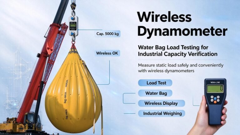
| Wireless dynamometers, load links and load pin shackles with their handheld displays, for periodic proof tests and load verification | Adaptation of your machine, mounting bracket design, welding, wiring to your hoist control panel, commissioning on site |
| Component-level certificates that come with the part: OIML R60-compliant load cell performance, material certificates, NIST-traceable factory calibration records where specified | Machine-level certification or type approval — CE marking of the crane, EN 13155 conformity, ASME B30 compliance, GB 12602 type approval of the limiter, or legal-for-trade approval of the whole arrangement |
| Engineering help with the weighing question: sizing, mounting position, load-path arithmetic, in-situ calibration procedure, and the interface to your controller | Structural redesign of your hoist, drum, sheave pack or equalizer, and any statement about whether your existing structure can take the added pin |
The asymmetry is deliberate. A load cell is OIML R60 component-level performance. OIML R60 certifies the cell as a component; it says nothing about the machine it is bolted into, and any supplier who blurs that line is selling you a problem that surfaces at the first insurance review.
4. Five sensor forms, and how the mounting position picks one for you
Nobody chooses a sensor form because they prefer it. The machine chooses it, because the machine has already decided where a force can be intercepted. There are five forms in common use on hoisting machinery.
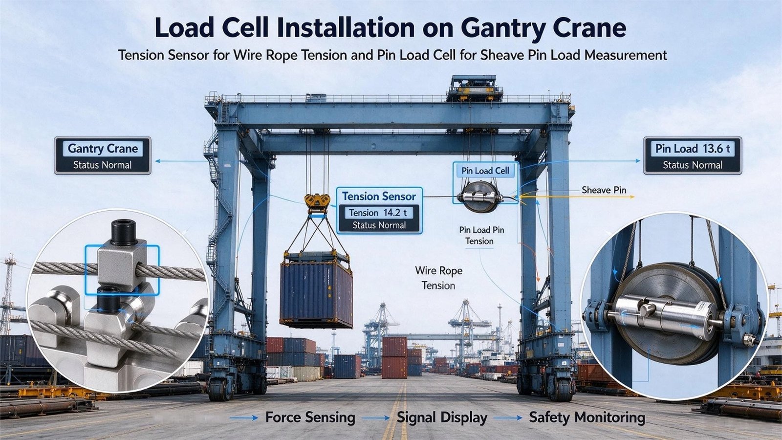
Shaft pin / load pin — replaces the pivot itself
The pin becomes the load cell. You take an existing pin out of a hook, a shackle, a travelling sheave block, a wedge socket, a turnbuckle head, a fork joint, a sheave axle bore — and put a sensor of the same envelope back in. It carries whatever that pin carried, which is usually 100 % of the load or exactly half of it. Used on tower cranes, hoists and gate hoists, rack-and-pinion construction elevators, port machinery and chain hoists. Sizes are custom: you get a drawing, you get an outer diameter, a length, a keyway and a bore pattern. There is nothing off-the-shelf about this, and anybody who quotes you one from stock is quoting an approximation.
Wire-rope tension cell (side-pressure / “clamp-on” type) — sits on the rope
This measures rope tension by pressing the rope against a sensing element across two support points. It installs at the dead end of the rope, which is the one place on a hoist with enough free length and no moving parts. It is the standard fit on electric chain hoists and on wire-rope direct-lift arrangements. The critical spec is not the load: it is the rope diameter the element is machined for. The same 20 kN cell exists in a version for φ10–φ18 rope and it will not fit φ24.
Bearing-housing type — takes the place of the bearing seat
A flat, low-profile block that goes under a bearing housing, replacing the bearing seat. Its flat form gives a stable load path, tolerates side load and shock well, and the double-ended shear beam inside gives good accuracy. It is the natural fit for overhead travelling and gantry cranes, where the drum or the sheave pack already sits in a bolt-on housing.
“Fish-back” sheave-axle type — reads the vector sum of the falls
A saddle-shaped sensor that sits beneath a fixed sheave axle (or a balance sheave axle) and reads the resultant force the two rope legs put on that axle. Common on overhead and gantry cranes and on gate hoists. Its advantage is that it intercepts the whole rope system in one place instead of a single rope leg, so rope-fall count and reeving friction cancel to a first order.
Plate-ring type — largely displaced, but still asked for
A ring with a machined sensing section that the load passes through. It has been mostly replaced in new limiter designs by the side-pressure type, because the side-pressure element is cheaper to install and easier to re-rope. It still appears in older Chinese designs and in customers who are copying an existing machine. I quote it when asked, and I say plainly that it is a legacy choice.
A load cell does not measure the load. It measures the force at the point where you installed it. Until I know the mounting point, I do not know the load path, and until I know the load path, every number on the datasheet is a number about a different machine. This is why the first thing I ask for is not a capacity — it is a photograph of the machine and a GA drawing with the candidate pin circled.
If you are still weighing up whether you need a permanent limiter or a portable instrument for periodic checks, that is a different article — I wrote it up separately in how to choose a wireless dynamometer, and I will not repeat it here. If your machine is a lift platform rather than a crane, the weighing question changes shape entirely — that one is covered in field notes from 200+ lifting platform projects.
5. Project 1 — Tower crane OEM in the Gulf: the pin that had nowhere to stop turning
Last year a tower crane builder in the Gulf sent me a single-line drawing and one sentence: “Need load pin, 40 ton, replace this pin, quote best price.” The drawing was a φ70 × 320 mm pin with a 30 mm axial bore, sitting in the balance sheave axle of the jib. Forty tonnes was the crane’s rated capacity at that radius.
I did not quote. I asked three questions, and only one of them was about the sensor.
Question 1: what stops this pin from rotating?
The drawing had no anti-rotation feature. Not a flat, not a keyway, not a keeper plate, not a drilled boss. The original pin did not need one — a plain steel pin is happy to rotate, that is what pins do. A load pin is not. Inside it there are strain gauges, a compensation network and four wires, and every rotation of the barrel works the wire where it leaves the gauge area. Their reply was honest and typical: “We will add a plate later.”
This is the single most common defect I see in pin-type inquiries, and it is why our own product page for custom shaft pins puts H7/g6 fit and an anti-rotation keeper plate in the installation section rather than in the small print. A pin that rotates will not fail on the test bench. It will fail after one season of jib movement, and it will fail as an intermittent signal that looks like an electrical fault. That failure signature — and how to tell it apart from a genuinely damaged cell — is set out in how to tell whether a load cell is damaged.
Question 2: is 40 t the force this pin actually carries?
It was not, and this is the second reason I ask for the reeving drawing before I open a quotation form. Their jib ran a four-fall reeving. A balance sheave axle under the fixed sheave block sees the resultant of both rope legs leaving that sheave, which in a four-fall system is roughly twice the most heavily loaded rope leg:
| Reeving | Most loaded rope leg, as share of hook load | Force at one balance / fixed sheave axle | Required cell range for a 40 t crane |
|---|---|---|---|
| 2 falls | 50.5 % | 101 % of hook load | 40 t plus margin |
| 4 falls | 25.8 % | 51.5 % of hook load | 20.6 t plus margin → 25 t |
| 6 falls | 17.5 % | 35.0 % of hook load | 14.0 t plus margin → 20 t |
(The share figures assume a sheave efficiency of 0.98 per sheave, which is the usual design value for a plain bearing in good condition. If your sheaves are on the way out, the share climbs.)
They would have received a 40 t load pin. Installed in a four-fall balance sheave, it would have read 51 % of the real load at rated capacity. The limiter would have been scaled by the integrator to make the display read correctly at one test point, and from then on every reading would carry the reeving error on top of the measurement error. The crane would have reached its rated capacity while the display showed about half. That is exactly the failure mode that turns a 4 % cause of death into a 22.7 % one.
Question 3: what is the working temperature on the jib, and how often does the pin get wet?
Gulf coast, salt air, 5 °C to 50 °C seasonally, and a mandatory washdown twice a year because of chloride build-up. We went with a stainless body and a sealed cable entry, and I put the temperature span in writing because it drives the zero-drift budget I will show you in section 9.
What we shipped and what it cost them
- A custom shaft pin, 25 t nominal range, stainless, H7/g6 interface, with a machined anti-rotation flat as well as a supplied keeper plate.
- A wiring schedule and a shielded 4-wire cable route with a drip loop, because on a jib every cable becomes a water channel.
- An in-situ calibration procedure with five test points, to be done after installation rather than on our bench.
The lead time went up by about three weeks because of the drawing changes. The alternative was a field failure in month nine. I have done that arithmetic with customers enough times now that they usually take the three weeks.
The lesson I keep re-learning: on a load pin project, the sensor is about 20 % of the work. The other 80 % is the pin envelope, the fit, the rotation restraint, the cable route and the reeving arithmetic. If your supplier quotes a load pin from the drawing alone without asking about reeving, you are buying a precision part for an imprecise question.
6. Project 2 — A steel service centre that asked for 0.05 % on an overload limiter
A steel service centre in Central Europe runs six overhead travelling cranes between 5 t and 20 t. They asked me for a retrofit overload limiter and their spec sheet had one line underlined: “Load cell accuracy: 0.05 % FS or better.”
I told them I would quote it, and that they should not buy it. Here is the arithmetic I sent them.
| Item on a 20 t crane | Value in % FS | Value in kg |
|---|---|---|
| What they asked for (cell accuracy) | 0.05 % | 10 kg |
| Zero drift of that same cell over a 10 °C step | 0.02 % | 4 kg |
| The same drift across their real 5 °C to 50 °C bay span (45 °C = 4.5 steps) | 0.09 % | 18 kg |
| Temperature effect on the reading, 0.05 %/10 °C cell sent to a hot bay (85 °C design span) | 0.43 % | 85 kg |
| Permitted action error under GB 12602-2009 (for reference) | 3.0 % | 600 kg |
The point of the table is the fourth row. A cell with a better accuracy figure and a worse temperature coefficient loses to a cheaper cell as soon as the bay is hot. The coefficient has to be multiplied by the range and by the temperature span before it means anything. A specification written as “0.05 % FS” without a temperature span attached is not a specification, it is a wish.
What actually decided the part
Two things that never appear on a customer’s spec sheet.
Bridge current and self-heating. Their bay is a heat soak. A cell excited at 10 V through a 380 Ω input bridge draws 26.3 mA and burns 263 mW in the gauge area. The same measurement at 750 Ω input draws 13.3 mA and burns 133 mW. Same excitation, same signal, roughly half the internal heat. On a cell that sits in a hot bay all day and is only re-zeroed once a shift, that difference shows up as a slow zero walk you cannot calibrate away. We quoted the higher-resistance bridge.
Ingress protection, including our own shortfall. Their original preference was a plate-ring tension cell we list as IP65 — and I told them that GB 12602-2009 asks a rated capacity limiter’s sensor to be IP68 and its indicator box IP42. GB 12602 is the Chinese standard and does not bind a Polish steel mill, but the direction of travel is the same everywhere: an overhead crane in a pickling line sees acid mist and a crane in a rolling bay sees scale and water. IP65 is sealed against jets of water; it is not sealed against being hosed down for ten years. Either specify the potted / higher-IP variant or accept replacement as a consumable. I would rather say that in a quotation than be the reason a limiter goes intermittent in year three.
I quoted the 0.05 % cell, with a note that said: “This is the part you asked for. It is not the part this crane needs, and here is the drift table that shows why.” They bought the 0.1 % cell with the better temperature behaviour and spent the difference on a proper in-situ calibration. That is a smaller order for me and a limiter that still trips correctly in February.
And the question I refused to answer
Their quality manager then asked me to confirm, in writing, that the limiter would make the cranes compliant with the Machinery Regulation. I declined, and explained why the request was aimed at the wrong party. A rated capacity limiter is a safety-related control function on a machine. The machine builder is the one who declares conformity, chooses the performance level, and owns the risk assessment. I supply a component with a component-level datasheet. Signing a machine-level statement I cannot test would be dishonest, and it would not protect them at an audit — it would just move the liability.
7. Project 3 — An electric chain hoist distributor who was measuring the wrong force
A hoist distributor in Southeast Asia was retrofitting overload warning onto a batch of electric wire-rope hoists. They had already chosen a wire-rope tension cell from our range — the 10 t version — and wanted to order 60 units.
I asked for the reeving drawing. Four falls, φ16 mm rope, 10 t hoist. Two problems, both fatal to the project as specified.
Problem 1: the rope diameter, not the load, picks the model
A side-pressure rope tension cell is machined to grip a specific rope diameter band. The published pairing is blunt about it:
| Rope tension range | Rope diameter the element is machined for | Nominal rope stress implied at φ6 / φ14 equivalent |
|---|---|---|
| 10 kN | φ6 – φ14 mm | 354 / 65 MPa |
| 20 kN | φ10 – φ18 mm | 255 / 79 MPa |
| 50 kN | φ16 – φ26 mm | 249 / 94 MPa |
| 100 kN | φ24 – φ36 mm | 221 / 98 MPa (at φ24 / φ36) |
| 200 kN | φ24 – φ36 mm | 442 / 197 MPa (at φ24 / φ36) |
Look at the middle column against the right-hand column and the point lands: the diameter band is a mechanical seating requirement, not a strength calculation. The implied nominal rope stress ranges from about 65 MPa to 440 MPa across the same product family, which is a factor of nearly seven. Every rope in that spread is a perfectly normal crane rope. If you pick the model by capacity alone and your rope does not seat in the groove, the element reads a fraction of the real tension and you will never find out on a bench.
Their rope was φ16 mm. The 10 kN element seats φ6–φ14. It would not fit. They needed the 20 kN version — not because the force demanded it, but because the rope did.
Problem 2: a 10 t cell would have read 26 % of full scale at rated load
Even if the rope had fitted, the mounting point was the dead end of a four-fall system. The most heavily loaded leg of a four-fall reeving carries 25.8 % of the hook load. On a 10 t hoist that is 2.58 t, or 25.3 kN. A 10 t (≈98 kN) cell at that point would work at 26 % of its range and, worse, the operator’s display would be wrong by a factor of 3.88 unless the controller scaling carried the reeving correction.
Two legitimate ways to fix it, and I told them both. Option A: keep the sensor at the dead end, size it for the rope tension (20 kN here, driven by the φ16 rope), and write the reeving factor into the controller with the efficiency assumption documented in the test report. Option B: move the measurement to the sheave pack and read the whole rope system in one place, so the reeving factor cancels and the installer has one fewer number to get wrong. Option B costs more hardware and less commissioning risk. They took B on the new machines and A on the retrofit fleet.
What goes wrong with Option A over five years
The reeving factor is not a constant. It depends on sheave friction, and sheave friction depends on bearing wear, rope lubrication and rope diameter loss from wear. A reeving factor calculated on new sheaves at η = 0.98 drifts upward as the sheaves degrade, and the indicated load drifts with it. Nothing is broken. The limiter is simply reading a machine that has changed around it.
That is the argument for re-verifying the limiter against a known load at least annually, and for putting the original reeving assumption and the sheave efficiency assumption into the machine file rather than into the integrator’s head. It is also the argument for a periodic check with a portable instrument — which is a different product from a limiter sensor, and I cover the trade-offs in the wireless dynamometer guide. The same single-point load-path reasoning shows up in a completely different industry in polished rod load on beam pumping units.
In all three cases the customer had already chosen the product family correctly and the number incorrectly. In all three cases the wrong number came from the same source: assuming the sensor sees the load. It sees a force at a point, and the conversion from that force to the hook load is a piece of machine design that has to be done before the sensor is ordered, not after the limiter starts showing strange values.
8. The three trip points that actually decide the specification
If your customer is in China, the limiter’s behaviour is not negotiable — GB 12602-2009 fixes it. If your customer is elsewhere, the national standards differ in wording but the three-step logic is the same, and it is worth understanding because it explains why a limiter sensor is specified the way it is.
| Parameter | GB 12602-2009 requirement | On a 10 t rated crane |
|---|---|---|
| Accuracy | Display accuracy < 5 % FS; action error < 3 % FS | < 500 kg display, < 300 kg action |
| Pre-alarm | Audible and visual alarm at 90 % of rated capacity | 9.00 t |
| Delayed alarm | Continuous alarm at 105 %, relay acts after a 1–2 s delay, cuts the hoisting power circuit | 10.50 t |
| Immediate alarm | Relay acts immediately at 110–130 %, cuts the hoisting power circuit | 11.00 – 13.00 t |
| Supply | 220 V or 380 V, 50 Hz | — |
| Environment | −20 to +60 °C, RH below 90 % | — |
| Ingress protection | Load cell IP68; indicator enclosure IP42 | — |
| Sensor overload capability | 1.5× rated capacity | 15.00 t |
Three things in that table are worth saying out loud.
First, the band between 100 % and 105 % is only 500 kg on a 10 t crane. The pre-alarm fires at 9 t, the hi-lo trips at 10.5 t. The operator has 1.5 t of warning between “something is wrong” and “the hoist stops”. That is a very narrow window to build with a drifting sensor.
Second, the 1.5× overload capability is a verification requirement, not an operating regime. The trip point is at 105 %. The counterweight sits at 150 %. That is 4.5 t, or 42.9 % of the trip point, of unused headroom that exists for exactly one purpose: so that a crane which has been overloaded, abused or shock-loaded still has a sensor left to trip the next time.
GB 12602 asks a limiter’s sensor for 1.5× rated capacity of overload capability. Our wireless dynamometers and load pin shackles — the WST901, WST905 and WST906 families — publish a maximum safe load of 125 % FS with an ultimate load of 400 % FS. One hundred and twenty-five percent is 20 % below the 1.5× that a limiter sensor is called on to survive.
That is not a defect. It is a different product for a different job. A wireless dynamometer is a portable verification instrument: you hang it on, you take a reading, you take it off. It is not permanently installed on a machine that may be shock-loaded while nobody is watching. If a customer wants to embed our wireless hardware as the permanent limiter sensor on a crane that has to satisfy GB 12602, I tell them the published overload figure does not get them there and quote them a wired sensor with the right margin instead. The ultimate-load figure is a survival rating, not a working rating, and I will not let the two be confused in a quotation.
Third, the standard fixes the trip points but says nothing about the dynamic load the sensor will actually see. That is where EN 13001-2 comes in, and it is the piece of the puzzle most retrofit projects miss.
The dynamic factors that decide whether 1.5× is enough
EN 13001-2 models the load a crane actually experiences as a set of multipliers on the nominal load. The one that matters for a load cell is φ2, the factor for the inertia of the lifted mass leaving the ground:
| Stiffness class | Static deflection δ | β2 | φ2 at 0.5 m/s | Headroom left if you sized at 1.5× static |
|---|---|---|---|---|
| HC1 | δ ≥ 0.8 m | 0.17 | 1.135 | +32.2 % |
| HC2 | 0.3 ≤ δ < 0.8 m | 0.34 | 1.220 | +22.9 % |
| HC3 | 0.15 ≤ δ < 0.3 m | 0.51 | 1.305 | +14.9 % |
| HC4 | δ < 0.15 m | 0.68 | 1.390 | +7.9 % |
Read the last column. Sizing a cell at 1.5× the static hook load leaves 32 % of margin on a floppy HC1 structure and only 7.9 % on a stiff HC4 structure, at the same hoisting speed. That is the whole difference between a comfortable design and one that is living on its reserve. A stiff crane is not necessarily a better crane for your sensor; it is a crane that punishes a load cell harder on every lift-off.
The other factors in EN 13001-2 stack on top of that when they apply: φ1 for the crane’s own dead-weight vibration (0.9 to 1.1), φ5 for drive acceleration (1 to 3), φ7 for buffer forces (1.25 to 1.95), and φ9, which is −0.3 for an accidental unhooking event. For tower cranes, EN 14439 caps φ2 at 1.3 in the A1 and B1 load combinations and leaves C1 uncapped. None of these are sensor parameters. All of them are reasons your sensor needs reserves.
9. Error budget: a 5 % system tolerance does not mean you can relax
The 5 % system tolerance in GB 12602 sounds like permission to be careless. It is not, and the reason is where the error actually accumulates.
| Contribution | Typical value, % FS | Whose problem it is |
|---|---|---|
| Cell non-linearity + hysteresis + repeatability, combined | 0.50 | Mine, and it is the smallest line here |
| Zero and span temperature effect over the real ambient span | 0.43 | Mine, and only knowable from your site data |
| Creep over a long lift | 0.05 | Mine |
| Indicator ADC, filtering and firmware rounding | 0.50 | Yours, or your integrator’s |
| Arithmetic sum of the electrical chain | 1.48 | — |
| Root-sum-square of the electrical chain (the more realistic figure) | 0.83 | — |
| Installation: off-centre loading, side load, unresolved rope geometry, mounting stiffness | 1.0 – 3.0 | Yours, and it is four times larger than everything I control |
| Whole system, RSS including a 2 % installation term | 2.16 | — |
| Whole system, arithmetic sum | 3.48 | — |
I control about 1.5 % FS of a budget that is allowed to be 3 %. The installation controls 1 to 3 % on its own. So when a customer wants to spend money on a better sensor, the honest answer is that the money is better spent on a bracket, a fit tolerance, a rotation stop and a five-point calibration — because those are the terms that are actually four times bigger than anything I can sell you.
Why I always multiply the temperature coefficient by the range
A datasheet line that reads “±0.02 % FS / 10 °C” is meaningless until you know the full-scale value and the ambient span. Take the same line at two different ranges:
| Cell and range | Zero shift per 10 °C | Across a −20 to +65 °C span (8.5 steps) | As a share of the 3 % action-error budget on a 10 t crane |
|---|---|---|---|
| 0.02 % FS/10 °C at 2 000 kN FS | 0.4 kN = 40.8 kg | 3.4 kN = 347 kg | 116 % — over budget |
| 0.05 % FS/10 °C at 200 kN FS | 0.1 kN = 10.2 kg | 0.85 kN = 86.7 kg | 29 % |
The cell with the worse temperature coefficient has the better absolute behaviour, because the range is ten times smaller. A coefficient is a multiplier, and a multiplier only means something when you know what it is multiplying. I have watched a project choose the wrong part precisely because the comparison was made on the coefficient alone. If you have ever sized a hopper or tank by the same logic, the trap is identical — I went through it in how to size load cells for hopper scales, and the summing side of it is in tank and silo weighing systems.
10. Where the sensor sits changes the number by a factor of four
On one machine, with one load on the hook, the force at the four candidate sensing points differs by a factor of four. This is the table I now send to every new hoisting inquiry, because it ends most of the confusion in one page.
| Mounting point | What it physically measures | Reading, as a share of a 10 t hook load | What I need from your drawing |
|---|---|---|---|
| Shackle pin above the hook | The whole hook load | 10.00 t (100 %) | Hook block hook-up drawing |
| Equalizer pin, two pins sharing the load | Half the hook load per pin | 5.00 t (50 %) | Equalizer arrangement and pin count |
| Dead end of the rope, 2 falls | Most loaded rope leg | 5.05 t (50.5 %) | Rope diameter and terminations |
| Dead end of the rope, 4 falls | Most loaded rope leg | 2.58 t (25.8 %) | Reeving diagram and fall count |
| Fixed sheave axle, 2 falls | Resultant of both rope legs | 10.10 t (101 %) | Sheave block section, axle diameter |
| Fixed sheave axle, 4 falls | Resultant of both rope legs | 5.15 t (51.5 %) | Sheave block section, axle diameter |
| Under one drum bearing housing | One side of the drum load | 5.00 t (50 %) | Drum bearing seat drawing, bolt pattern |
The same 10 t hook load produces anything from 2.58 t to 10.10 t at the sensor. That is a factor of 3.9, and it is the reason a quote built from the crane’s rated capacity alone is a guess with a serial number on it.
It also explains why the range spread in the products I quote is so wide. One family of plate-ring tension cells covers 20 kN to 2 000 kN — a 100:1 spread — because the mounting point decides whether you need 2.5 t or 200 t of range for the same machine. Choosing the range is not about the crane. It is about the pin.
I now open every hoisting inquiry with: (1) how many parts of line carry the hook block, and what is the rope diameter? and (2) where on the machine do you want the sensor to sit? Both answers come off a drawing that already exists. Until I have them, I can give you a range and a price, and I will tell you it is provisional.
11. Proof load, in-situ calibration, and who signs the certificate
A load cell leaves our factory with a calibration certificate. That certificate says what the cell does on a press, at 20 °C, bolted to a fixture. It is the beginning of the accuracy discussion, not the end of it, and I make sure every customer understands the difference before the order is placed.
In-situ calibration is the only calibration that counts
Once the pin is in the machine, installed at the real fit, loaded through the real rope geometry, the transfer function changes. The procedure I send with every pin project is:
- Apply known loads at five points across the working range, not three. Three points detects a slope error; five points shows you whether the error is a curve.
- Run each point in both directions, so hysteresis is visible rather than averaged away.
- Record the points in the machine file, not in a notebook in the maintenance office.
- Recalibrate annually, and after any significant overload event. A pin that has been shock-loaded has not necessarily failed, but its zero has moved, and the shift is not visible without a reference.
A factory certificate alone also runs into a legal problem the moment the reading is used for trade. Crane scales sit in Class III L in the US system (NIST Handbook 44), the same class as vehicle scales, axle-load scales and livestock scales, with a maximum of 10 000 divisions and a minimum of 100. And in that regime maintenance tolerance is exactly twice acceptance tolerance — a device that passed when new is allowed to be twice as far out once it is in service. If your customer intends to invoice on a crane scale reading, none of that is optional, and it has nothing to do with the load cell’s datasheet accuracy.
OIML R76 states across its editions that a non-automatic weighing instrument used outdoors without environmental protection must not exceed 3 000 divisions. A crane is the most outdoors machine there is. Wind alone can be worth a scale division or two: published analysis shows an 8 m² wind-facing area in a force-6 gust at 45° producing nearly 70 kg of error, and standing water on a 3.4 × 18 m platform producing 153 kg. Neither of those figures has anything to do with the cell. Both of them will appear on a weighbridge-style acceptance test and ruin your day. If the reading is going to be used for trade, put it indoors or accept a coarse division.
The 20 000-cycle line nobody asks about
EN 13155 — the standard for non-fixed load lifting attachments — sets a boundary that surprises people. Its structural mechanical-strength clauses cease to apply once an attachment is designed for more than 20 000 lifting cycles; below that figure, no fatigue verification is required, in line with FEM 1001. Run the arithmetic on a busy production hook:
| Lifting cycles per day | Days to reach 20 000 cycles | Years, at 250 working days |
|---|---|---|
| 20 | 1 000 | 4.0 |
| 50 | 400 | 1.6 |
| 100 | 200 | 0.8 |
| 200 | 100 | 0.4 |
A hook that runs 100 lifts a day exits the standard’s simple structural route in eight months. That is why I now ask for the daily cycle count alongside the capacity. It is the difference between a part you buy once and a part you should be inspecting on a schedule.
None of this is load cell design. All of it is what decides whether your load cell is still trusted in year three. The relevant sibling article for the wider weighing-core argument is how I size a weigher for concrete batching, where the same tolerance-versus-drift trade-off plays out in a much more forgiving environment.
12. Seven mistakes I see repeated, and the 7-step path I use now
These are the seven that come back over and over. Every one of them has cost somebody a field visit.
| The mistake | What it costs |
|---|---|
| Specifying accuracy before specifying the mounting point | You optimise the smallest term in the budget and ignore the largest one. Typically 0.5 % FS spent to protect against 2 % FS of installation error. |
| Ordering a load pin without an anti-rotation feature | Internal wiring fatigue. Surfaces in month six to month twelve as an intermittent signal that gets misdiagnosed as an electrical fault. |
| Treating rated capacity as the sensor range | On a four-fall reeving the sensor reads 25.8 % of the hook load. The limiter is scaled to compensate, and then every reading carries the reeving assumption. |
| Choosing a rope-tension cell by capacity instead of by rope diameter | The rope will not seat in the element. The device reads a fraction of the real tension and the error looks like drift, so people chase the electronics. |
| Using a portable dynamometer as a permanent limiter sensor | Max safe load 125 % FS is below the 1.5× overload capability GB 12602 asks of a limiter sensor. Fine for a proof test, wrong for a permanent installation. |
| Forgetting the temperature span | A 0.02 % FS/10 °C cell on a 2 000 kN range drifts 347 kg across an 85 °C span. On a 10 t crane that consumes 116 % of the permitted action-error budget before anything else is added. |
| Assuming the cell’s certificate makes the machine compliant | It does not, and the assumption is discovered at the first insurance or inspection event, usually after the invoice is paid. |
The 7-step path I use on every hoisting inquiry
- Machine class and duty. Which of the nine families, what is the rated capacity, what is the radius, how many lifting cycles per day, and is the reading used for trade?
- The candidate mounting point. Photograph of the machine plus a GA drawing with the pin circled. No circle, no quote — I have never once regretted waiting for that drawing.
- The force at that point. Fall count and rope diameter from the reeving diagram, then the factor table in section 10. This is where the customer’s number usually changes.
- Range, including dynamics. Static force, then φ2 for the structure class, then the overload capability the applicable standard asks for. If the two conflict, the standard wins.
- Mechanical interface. Envelope, fit tolerance (H7/g6 as a default), anti-rotation feature, cable entry direction, drip loop, sealing class. All of this goes on the drawing before the order is placed.
- Electrical and calibration plan. Excitation and bridge resistance, the indicator and its scaling factor, the reeving multiplier if there is one, a five-point in-situ calibration, and a recalibration interval written into the machine file.
- Ownership. Which documents I issue (component datasheet, factory calibration record, material certificate) and which documents somebody else issues (declaration of conformity, risk assessment, inspection certificate). In writing, in the quotation.
Steps 3 and 4 are the ones that make customers slightly uncomfortable, because they are the steps where the number they sent me turns out to be wrong. That discomfort is the value. Every project in section 5 to 7 went better because of a step 2 that arrived late and a step 3 that contradicted the inquiry.
13. Who owns what: a standards map for hoisting machinery
This is the table I keep open when a customer starts quoting standard numbers at me. The point of it is the last column.
| Standard | What it actually governs | Who owns compliance |
|---|---|---|
| EN 13001-2 | Load actions on cranes: the φ dynamic factors, stiffness classes, load combinations A/B/C | Crane designer / OEM |
| EN 15011 | Bridge and gantry cranes as machines, including their safety devices | Crane builder |
| EN 14439 | Tower cranes; caps φ2 at 1.3 in the A1 and B1 combinations and leaves C1 uncapped | Crane builder |
| EN 13155 | Non-fixed load lifting attachments: plate clamps, vacuum lifters, lifting magnets, lifting beams, C-hooks, forks, clamps, lifting inserts | Attachment maker |
| EN 13155 — exclusions | Expressly does not cover slings, ladles, expanding mandrels, buckets, grabs or grab buckets, and does not cover powered container spreaders. It also excludes food and pharmaceutical contact, hazardous materials, explosive atmospheres, noise, lifting of persons, electrical hazards, and hydraulic or pneumatic components. | Somebody else, or nobody |
| EN 13155 — 20 000 cycles | Its structural mechanical-strength clauses stop applying above 20 000 lifting cycles; below that, no fatigue verification is required (consistent with FEM 1001) | Attachment maker, but you should be counting cycles |
| EN 15056 | Powered container handling spreaders — carved out of EN 13155 | Spreader maker |
| ASME B30 series | US practice for cableways, cranes, hoists, hooks and rigging hardware; load safety is squarely in the OEM’s scope | Crane builder / owner |
| ISO 4309 | Wire rope care, maintenance, examination and discard criteria | Rope supplier and inspector |
| GB 12602-2009 | China: the crane overload protection safety device itself — the 90 / 105 / 110–130 % trip points, the 1.5× sensor overload capability, IP68 sensor, IP42 indicator box | Limiter integrator, inside the crane builder’s machine conformity |
| China: State Council Order No. 114 | Defines which lifting equipment counts as regulated special equipment (0.5 t lifts, 3 t / 2 m cranes, two-level parking systems) | Owner and inspection body |
| OIML R60 | Component-level load cell performance. It is about the cell, not the machine. | Me — this is my layer |
| OIML R76 | Non-automatic weighing instruments: classes, Min, mpe, temperature range, and the rule that an unprotected outdoor instrument must not exceed 3 000 divisions | Whoever builds the weighing instrument |
| NIST HB 44 / NTEP | US trade weighing. Crane scales sit in class III L. Maintenance tolerance is twice acceptance tolerance. | Whoever wants to invoice with it |
| Regulation (EU) 2023/1230 | EU machinery legislation, replaced from 20 January 2027. A crane’s safety functions and their control systems belong to the machine, not to a component. | Machine builder / importer |
If you take one thing from this table, take the EN 13155 exclusion list. It is the cleanest statement in lifting standards that what is outside a standard’s scope is not thereby unregulated — it is simply somebody else’s problem. Grab buckets, slings, spreaders and the limiter function itself all sit outside the attachment standard. Every one of them is real, and every one of them belongs to a party that is not the load cell supplier. The multi-axis version of the same ownership question — when a force has components you did not plan for — is covered in choosing between 3-axis and 6-axis force sensors.
14. Where the weighing core ends
I want to be very explicit about this, because it is the part of the conversation where suppliers usually get vague and buyers get hurt.
What I am: a manufacturer and exporter of the weighing core — strain gauge load cells, force sensors, junction boxes and weighing indicators. On a hoisting machine, that core is the sensor in the load path, the summing arrangement if there is more than one sensor, and the controller that turns millivolts into a number and a relay state.
What I am not: a crane builder, a limiter house, or a safety integrator. I do not offer safety-rated components. I will not sign a risk assessment, a declaration of conformity, a CE file or an inspection certificate for your machine, because I cannot test the thing those documents are about. I do not redesign your hoist, your drum, your sheave pack or your equalizer, and I will not tell you that your existing structure can accept the additional pin — that is a structural engineering question and it belongs to the party who signs the drawing.
- Specification tables with the actual test conditions
- Dimensional drawings to your envelope
- A wiring schedule and connection diagram
- Factory calibration data with the test points
- A written statement of the reeving and mounting assumptions I used
- A statement that your crane complies with anything
- A safety integrity or performance level claim
- A guarantee that a wireless unit will serve as a permanent limiter
- Approval for a sensor depth or IP rating beyond the tested figure
- Silence about the parts of your project I cannot do
One more piece of self-disclosure, because customers find it eventually and I would rather they heard it from me. Our product pages are written by engineers and they are not perfect. The WST702 page publishes its capacity, accuracy and bridge resistance but no ingress protection figure and no ultimate overload — I quote those from the test report instead of pointing at the page. The WST905 page gives complete dimensions and accuracy but no bridge resistance or rated output, so you cannot design the electronics from it alone. The WST706 page is titled as a rope tension sensor, and it is — for filaments, yarns, cables and belting up to 100 kg. It is not a crane part, and I will say so if you ask me for one for a hoist. The WST701 page carries an IP68 submersible depth figure that reads like it was copied from a subsea connector datasheet; I quote the depth we actually test to.
I would rather tell you where my own documentation is thin than have you discover it during integration. If you need the junction box wiring convention for a multi-cell summing arrangement, we cover it in the load cell junction box wiring and adjustment guide rather than in a marketing page. If this is your first custom load cell project of any kind, the generic decision order is in how to choose the right load cell for your project.
15. Load cells for hoisting machinery: the seven parts I actually quote
Seven parts I actually quote when a customer asks about load cells for hoisting machinery. Each one carries the same honesty tag: what it is good at, and what it will cost you.

WST403
- Range 20 – 2 000 kN
- Combined error ±0.03 – 0.1 % FS
- Output 1.5 / 2.0 mV/V, 380 Ω in, 350 Ω out
- Safe overload 150 % FS, ultimate 200 % FS
- −20 to +65 °C, creep ±0.02 % FS / 30 min
The widest range in the group and the one I use for hook scales, port and quay work. The cost: it is rated IP65, which is below the IP68 that GB 12602 asks of a limiter sensor — for a permanently installed limiter in a washdown environment you should ask me for the higher-IP variant rather than assume the datasheet figure is enough.
WST702
- Range 10 / 20 / 50 / 100 / 200 kN
- Combined error 0.3 % FS, output 1.0–1.5 mV/V
- 750 Ω in, 700 Ω out — half the bridge current of a 350 Ω cell
- Safe overload 150 % FS, alloy steel
- Built for long-term rope tension measurement and monitoring
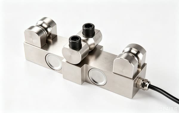
This is the workhorse for dead-end installations on chain hoists and wire-rope direct lifts, and the 750 Ω bridge makes it the better choice in a hot bay. Two costs: the page publishes no ingress protection figure and no ultimate overload, so ask me for the test report numbers before you write IP into a specification; and the rope diameter band, not the capacity, decides which model fits.
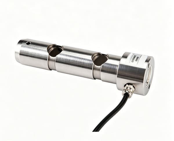
WST701
- Range 50 – 1 000 kN, accuracy 0.5 % FS
- Sensitivity 1.0–2.0 mV/V, 750 Ω in, 700 Ω out
- Maximum safe overload 150 % FS
- Sizes manufactured to your envelope
- Double-ended shear beam, resistant to bending and off-centre load
The part for hook loads, winch forces and overload protection on tower, mobile and overhead cranes, and the one I sized for the tower crane in section 5. Costs to plan for: 50 kN is the smallest range, so small hoists need a different family; and the design assumes you supply an H7/g6 fit and an anti-rotation keeper plate — if you skip those, no accuracy figure will save the reading.
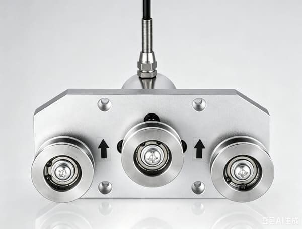
WST706
- Range 0.5 / 1 / 2 / 5 / 10 / 20 / 50 / 100 kg
- Linearity and repeatability 0.03 % FS
- Sensitivity 1.5–2.0 mV/V, 350 Ω bridge, IP65
- Safe overload 150 % FS, ultimate 200 % FS
- Steel and aluminium alloy body, φ5 mm cable
I am listing this one precisely so nobody buys it by accident. The page title says rope tension and that is accurate — it is a tension sensor for filaments, yarns, wire, cable and belting up to 100 kg, with excellent linearity for that job. It is not a hoisting load cell. The best range in the family is 100 kg. If you are tensioning a fibre line it is the right part; if you are lifting a container it is the wrong one, and I will tell you that before you order it.

WST901
- Accuracy 0.05 % (1–50 t), 0.1 % above 50 t
- Size table runs 1 t to 200 t, divisions 0.5 kg to 100 kg
- Supplied with G2130 high-tensile anchor shackles, galvanised
- Two user-programmable set points for warning and limit duties
- Peak hold, tare, unit switching; 25 mm 5-digit backlit display
My first recommendation for periodic proof tests, pre-delivery verification and spot checks, and the set points make it useful for one-off load limiting. The costs: this is a portable instrument (max safe load 125 % FS, ultimate 400 % FS) and 125 % is below the 1.5× a permanently installed limiter sensor is asked for; and the page title says 5 t / 10 t while the size table starts at 1 t, so quote from the table, not the title.

WST905
- Capacities 20 / 30 / 50 / 100 / 200 / 500 t
- Accuracy 0.5 % (1–50 t), 1 % above 50 t
- Ultimate load 300 % FS, IP66
- Two operator-set load control points for alarm and weight control
- 18650 lithium cell; more than 100 hours per charge
The one for large lifts — port equipment, heavy fabrication, water-bag proof loading. Two costs to know up front: the page publishes no bridge resistance and no rated output, so you cannot design the signal chain from the page alone, and it publishes no safe-overload percentage, only the 300 % ultimate figure. And 20 t is the smallest capacity, which rules it out for ordinary workshop cranes.

WST906
- Capacities 5 / 10 / 20 / 30 t
- Accuracy 0.1 %, IP67
- High-tensile carbon steel, tare range 100 % FS
- 433 MHz, 200 m line-of-sight; 280D handheld indicator
- 18650 lithium cells in both body and indicator
The practical choice when the load already hangs from a shackle and you want a number without cutting the lifting gear. Same portable-instrument caveat as the WST901 — max safe load 125 % FS, so it verifies loads, it does not sit permanently in a limiter circuit. Working range stops at +50 °C, which matters on a hot bay or a Gulf quay.
Two of these families run far wider than their page titles suggest. The WST403 is titled as a 5 t / 10 t crane scale part and its actual range is 20–2 000 kN. The WST901 is titled 5 t / 10 t and its size table runs 1 t to 200 t. Quote from the specification table, and if you only need one number from this article, make it this one: the title is marketing, the table is the product. Nothing in the permanent-limiter conversation should be based on a page title.
16. Frequently asked questions
What is the difference between a load cell for hoisting machinery and a crane scale?
A crane scale is a complete finished product: a load cell, a housing, a display and a hook, sold as one item, usually with a legal-for-trade classification such as OIML class III L. A load cell for hoisting machinery is a component that a crane builder or an integrator embeds. I supply both ends of that spectrum, but the OIML R60 certificate on our load cells is a component-level document. It tells you what the cell does on a press, not what the finished machine does in service.
Can I use a wireless dynamometer as a permanent overload limiter on my crane?
Not with our published figures, and I will say so before you order. GB 12602-2009 asks a limiter sensor to survive 1.5× rated capacity. Our wireless dynamometers and load pin shackles publish a maximum safe load of 125 % FS — 20 % short of that. They are excellent verification instruments: you hang one on, take the reading, take it off. If you want a permanently installed limiter sensor with the right overload margin, I quote a wired cell instead.
What accuracy does a crane overload limiter actually need?
Not much. GB 12602-2009 permits a display accuracy below 5 % of full scale and an action error below 3 % of full scale, and notes that a transducer between 0.1 % and 0.5 % is sufficient. On a 10 t crane, 3 % of full scale is 300 kg, while a 0.1 % cell contributes 10 kg — a 30 to 1 margin. What matters far more is long-term stability, temperature behaviour and overload capability, because those are what make the limiter still correct in year three.
How do I choose between a load pin and a wire-rope tension cell?
The machine decides it, not a preference. If there is an existing pivot pin in the load path that you can replace, a load pin puts the sensor directly in the load path and sees 100 % of the hook load — or exactly half if two pins share it. If the only accessible place is the rope itself, a wire-rope tension cell installs at the dead end, but it then measures rope tension rather than hook load, and the conversion factor depends on the number of falls and on sheave efficiency. That is one more number for somebody to get wrong, which is why I prefer the pin whenever the structure allows it.
What overload capability does a limiter sensor need?
GB 12602-2009 asks for 1.5× rated capacity. Note what that means in practice: the hi-lo trip point is at 105 % of rated capacity, so the gap between the trip and the 150 % verification point is 42.9 % of the trip point. That reserve exists for shock loads, abuse and repeated overload events. It is not an operating range, and a cell that has been run at 150 % repeatedly has consumed its reserve even if it still passes a bench test.
Does a load cell calibration certificate make my crane compliant?
No, and I will not imply otherwise. A factory certificate states the cell’s theoretical output on a press at a controlled temperature. Machine conformity — EN 15011 for bridge and gantry cranes, EN 14439 for tower cranes, ASME B30 in the US, GB 12602 for the limiter device in China — belongs to the crane builder or the limiter integrator. I supply the component datasheet and the calibration record. I do not sign a risk assessment, a declaration of conformity or a safety integrity claim.
How often should a hoisting load cell be recalibrated?
Annually, and after any significant overload event. Factory calibration is done on a press; the moment the pin is installed at the real fit tolerance, through the real rope geometry, the transfer function changes. I recommend a five-point in-situ calibration run in both directions, with the results written into the machine file rather than into a notebook. Five points rather than three, because three points detect a slope error but five points show whether the error is a curve.
Why does my limiter reading drift over time?
Usually not the electronics. Three mechanical causes dominate. First, sheave wear changes the reeving efficiency, so a dead-end sensor on a progressive system reads higher as the machine ages. Second, thermal drift moves the zero — a coefficient of 0.02 % FS per 10 °C on a 2 000 kN range is 40.8 kg per 10 °C, which is fine at the low end and 347 kg across the full span. Third, contamination and a rotting cable entry change the insulation. The fix starts with measurement, not with a new sensor.
A photograph of the machine, the reeving diagram, and where you think the sensor should sit. I will come back with the force at that point, the range I would choose, the dynamic and overload margin that goes with it, and a written statement of what I am not covering. If the number you sent me is the wrong one, you will hear that first.
VektorForce · load cells, force sensors, junction boxes and weighing indicators · www.vektorforce.com · Robin@vektorforce.com