
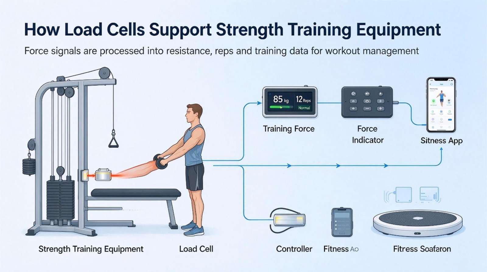
Load Cells for Strength Training Equipment: Two Jobs, One Cell
A load cell for strength training equipment answers one of two questions, and they are not the same question. One machine counts what you lifted and adds it into a score. The other draws the force curve of a single five-second effort. I quote the same strain-gauge families into both builds, and the part each one needs is almost never the same part. This is what I learned from three orders in Toronto, Melbourne, and Stockholm.
Load Cells for Strength Training Equipment: Two Jobs Under One Word
Two companies I have been reading this month sit at opposite ends of the same category. The first is a Canadian builder of a home and studio strength system. Their whole product promise is a number: this session you moved 9 350 lb, you are 650 lb from a 10 000 lb goal, this week 30 000 lb, this month 120 000 lb. The hardware measures; the app adds it up; the score is the product. The second is an American performance-assessment supplier whose isometric force device publishes 1 500 Hz sampling, 1 000 kg capacity, peak force, rate of force development, and a force-time curve at any joint angle. Their whole product promise is a shape: the curve of one effort, five seconds long, sampled so finely that the first 50 milliseconds are visible.
I do not supply either of them. I am using their published specifications because they are the two cleanest public examples of a split that runs through every strength and rehab machine I quote: the same word, “force,” doing two jobs that a load cell has to be chosen for separately. I call them the accumulator and the oscilloscope, and once you name them, most bad specifications I see in this market name themselves.
| What the job needs | The accumulator | The oscilloscope |
|---|---|---|
| Answers | How much did you move, all of it? | What did one effort look like? |
| Time span of one reading | 45 to 90 minutes, then summed over weeks | 2 to 5 seconds |
| Useful signal bandwidth | Under 1 Hz | 5 to 35 Hz |
| What decides quality | Zero stability, creep, temperature drift | Frame stiffness, anti-alias filtering, sampling |
| How the error behaves | An offset is added to every repetition | Noise lands once, on one curve |
| The number that ruins it | Zero balance, in kilograms | Natural frequency, in hertz |
Accumulation is a sum. Sums are patient with noise and merciless with offset.
That sentence is the whole article in one line, and it is the reason the two jobs cannot share a specification sheet. If your reading is random noise, adding 88 repetitions divides the damage by a factor of about nine — the errors cancel. If your reading carries a small constant offset, that offset is inside every one of the 88 repetitions and it is still there, at full size, in the total. A scale that reads 20 g heavy is a nuisance. An accumulator that reads 20 g heavy has told you a number that is 20 g heavier for every repetition you have ever performed.
The oscilloscope has the opposite allergy. Nothing is summed, so a stable offset across the session can be zeroed out for free before the test even starts. What cannot be fixed after the fact is anything that happens inside the measurement window: the moment the frame rings, the moment the anti-alias filter rolls off, the moment the display has already averaged your first 50 milliseconds into one number. You cannot re-run a maximal effort, so the instrument has to get the window right the first time.
I sell the sensing layer into builds like these: the load cell, the junction box, the indicator. I do not build the machine, the frame, the app, or the type-approved instrument — that is the OEM’s scope, and in this market the OEM is usually the one taking the liability. If you want the general method first, the complete guide to load cells covers principles and families, and the selection guide covers the sizing conversation. This article is narrower: what the two jobs do to the choice.
What a Volume Score Actually Measures
When a customer writes to me and says their volume score is drifting, my first question is never about the load cell. It is: where does your firmware get the load number from? In a cable machine, a plate-loaded machine, or a band rig, there are three quantities that all get called “the load,” and only one of them is inside the electronics.
| The number | Who owns it | How far it drifts in practice |
|---|---|---|
| Stack nominal | The plate supplier, stamped on the casting | Measured spread of 6.2 % across a five-plate set |
| Cable tension | This is what your load cell sees | 11.5 % one-way loss through a three-sheave path |
| Force at the handle | The athlete | Depends on ratio, friction direction, and cable angle |
A score that multiplies “stack nominal” by repetitions is not measuring the third row. It is measuring a stamped number and trusting it. A score built from a load cell measures the second row, which is honest about tension and silent about everything between the cable and the hand. Neither is wrong; they just answer different questions, and the marketing copy almost always describes the third row while the hardware reads the second.
Sheave losses are the largest single term. A clean ball-bearing sheave on a steel cable returns somewhere between 93 % and 97 % of the tension it receives; greasy bronze bushings and worn nylon pulleys are worse. At 96 % per sheave, a two-sheave path keeps 92.2 % of the load and a three-sheave path keeps 88.5 %. The third sheave costs you 3.7 percentage points of the reading, and it will cost the same 3.7 points in the opposite direction when the cable returns, which is why the machine feels easier going up than coming down. Your load cell sees both directions correctly. Your score, which assumes one ratio, does not.
Cast plates are the second term, and almost nobody weighs them. I asked one customer to put five of their standard 5 kg plates on a laboratory balance. The set came back at 4.87, 5.09, 4.94, 5.18, and 4.92 kg. The average is exactly 5.000 kg, which is why buying a random plate feels fine. The spread is 0.31 kg across the set, 6.2 % of nominal, and the heaviest single plate is 3.6 % over. If your firmware counts plates rather than kilograms, that 6.2 % lives permanently in your score, and it is not noise you can average away.
| Error term in a cable based volume score | Per reading | Across 88 repetitions |
|---|---|---|
| Sheave losses, three-sheave path | 11.5 % of the load, one way | Unchanged: systematic, and it never averages out |
| Plate nominal spread, five-plate set | 6.2 % of nominal across the set | Unchanged: stamped numbers do not drift |
| Zero balance left in the reading | 9.0 kg, fixed | 792 kg = 1 746 lb |
| Cell comprehensive error | 0.30 kg | 26.4 kg = 58 lb |
| The same 0.30 kg, if it were random | 0.30 kg | 2.81 kg = 6 lb, because errors cancel |
The arithmetic that decides the argument. Take a mid-size cell, 300 kg rated, 0.1 %F.S comprehensive error, zero balance published as ±3.0 %F.S. In kilograms, the comprehensive error is 0.30 kg per reading and the zero balance is a fixed ±9.0 kg that never goes away until software removes it.
A 10 000 lb training day at a 40 kg average is 113 repetitions; at 60 kg average it is 76. Take 88 repetitions as a round session. The cell error contributes 26.4 kg, or 58 lb. The unremoved zero offset contributes 792 kg, or 1 746 lb — 17.5 % of a 10 000 lb day, and about 21 000 lb across a 120 000 lb month. One number is 30 times the other, and it comes from a specification line most buyers skim past.
Now put the sensor error in context. The same 0.30 kg per repetition, if it were random noise rather than a systematic error, would contribute 0.30 × √88 = 2.81 kg across the session, because independent errors partially cancel when you sum them. That is 6.2 lb against 1 746 lb. The entire sensing chain is roughly one per cent of the load-path error budget, and the only reason its contribution is visible at all is that the offset is systematic while the sheave losses are merely large.
Toronto, March 2026: the job where I did not sell a cell
A Canadian builder of a home and studio strength system came to me with a precise complaint: participants were finishing sessions ahead of goal, and the feeling in the room was that the machine was “running fast.” Their diagnosis was the sensor. My first request was a photograph of the cable path and a note on how many sheaves it passes, and my second request was that they weigh five plates.
The photograph showed three sheaves. The plates came back with a 6.2 % spread. Their firmware converted plate count to kilograms using the stamped nominal, and applied a fixed ratio that matched the machine at mid-stack. I wrote them a two-page note that said, in plain words, that no load cell I could sell would move their number, and listed what would: drop from three sheaves to two, put the real ratio in firmware as a constant they could calibrate per machine, and re-zero automatically at the start of every session instead of trusting the reading from the last boot.
Three weeks later they came back and ordered cells anyway — but for a different reason than accuracy. The flat-profile family fitted the new two-sheave bracket without a machined spacer, and it carried an IP65 rating the previous part did not. Session-to-session repeatability of the score went from about ±4.2 % to about ±1.1 %, a factor of 3.8. The order was 40 flat-profile tension cells. Their score did not improve because the sensor was better. It improved because the load path stopped lying.
I can sell you a cell that is accurate to 0.02 %. I cannot make your cable honest.
A zero offset is invisible on any single lift. It is 17 % of your monthly score.
One more consequence of the arithmetic worth stating out loud, because it changes what you ask your supplier for. In an accumulator, a light warm-up set carries the worst relative error of the day. The same 0.30 kg is 1.5 % of a 20 kg set, 0.5 % of a 60 kg set, and 0.33 % of a 90 kg top set. If your product promises a score to the nearest pound, the honest unit of that promise is the poorest set in the session, not the heaviest. Nobody has ever been disappointed by a score rounded to the nearest 10 lb. Plenty of people have been disappointed by a score that claims precision the warm-up cannot support.
There is one more term that belongs in this budget and that trainers notice long before engineers do: the two halves of a repetition do not carry the same load. Published training protocols routinely run the lowering, or eccentric, phase at 20 to 40 % above the load of the lifting phase, because a muscle can resist more than it can lift. On a cable machine that difference arrives through a load path whose friction reverses between the two directions — the sheave that gives back 96 % on the way up takes 96 % on the way down, but the loss now sits on the other side of the handle. A single ratio constant calibrated on the lifting phase is therefore wrong on the lowering phase by an amount of the same order as the sheave loss itself. If your score counts both halves, it is counting one of them with a coefficient nobody measured; if it counts only the concentric phase, say so in the copy, because the training advice built on top of it depends on which one you meant.
The 1 500 Hz Question
Every second enquiry I get for an assessment device contains the same sentence: we need a load cell that can do 1 500 Hz. It arrives as a requirement, and it is almost always a number inherited from a converter datasheet rather than derived from the measurement. So I ask one question back, and it is the same question I ask about capacity: what is the shortest feature in the curve that you need to see?
The rule that turns a feature into a bandwidth is the rising-time rule, roughly bandwidth = 0.35 divided by the 10 % to 90 % rise time of the fastest thing you intend to resolve. Isometric force is not fast. A full maximal voluntary contraction reaches its plateau with a rise time on the order of 150 to 300 milliseconds; the classic rate-of-force-development window is the first 200 milliseconds. If you only want the overall shape of the effort, the required bandwidth comes out around 1.75 Hz. If you care about the slope inside the first 50 milliseconds — the part that separates a good rate of force development from a slow one — you need about 7 Hz. If you are chasing structure inside the first 10 milliseconds, you need 35 Hz, and at that point you are no longer measuring a muscle.
| What you want to see | Rise time of the feature | Bandwidth needed | Sample rate at 10× rule |
|---|---|---|---|
| Overall shape of a maximal effort | 200 ms | 1.75 Hz | 18 Hz |
| Rate of force development, first 200 ms | 50 ms | 7 Hz | 70 Hz |
| Initial slope, first 50 ms | 10 ms | 35 Hz | 350 Hz |
| Structural ring-down you want to filter out | 5 ms | 70 Hz and up | 700 Hz and up |
Read the bottom row against the top row and you can see the whole argument. The signal you want lives under 10 Hz. The disturbance you want to reject lives above 70 Hz. The gap between them is where the engineering happens, and it is roughly a decade wide — which is why a converter running at 1 500 Hz is not wrong, it is simply 214 times faster than the signal it is asked to digitise. Sampling faster than the signal costs nothing except power, storage, and a false sense of what is being measured. Sampling slower than the disturbance does cost something, because the ring-down does not vanish. It folds down into the curve and looks like biology.
The bottleneck is not the cell. It is almost never the cell.
Here is the part that surprises engineers who come to this market from industrial weighing. The strain-gauge cell itself is a fast device. Its elastic element has a natural frequency in the kilohertz range, and its output is analog — it has no sample rate at all. If you put a load cell straight into a bridge amplifier with a decent anti-alias filter, you can measure tens of kilohertz with an ordinary part. Nothing in the sensing element is holding you back.
What holds you back is everything you put after it. A weighing indicator built for commerce is designed around a different problem: it wants a stable, repeatable number for a load that is standing still, so it filters hard and updates slowly. The usual rates are 10, 20, and 80 readings per second, and there is a good reason for each. At 80 readings per second, one sample lands every 12.5 milliseconds. A 200 millisecond rate-of-force window contains 16 points. The first 50 milliseconds — the part that decides whether the curve is worth publishing — contains four points. Four points is not a curve. It is a rumour of a curve.
| Stage in the chain | Typical rate | Points in a 200 ms window | Points in a 50 ms window |
|---|---|---|---|
| Commercial indicator, slow setting | 10 readings per second | 2 | 1 |
| Commercial indicator, fast setting | 80 readings per second | 16 | 4 |
| Bridge acquisition card | 1 000 Hz or more | 200 | 50 |
| Assessment hardware in the market | 1 500 Hz advertised | 300 | 75 |
So the honest sentence in a specification is not “the sensor does 1 500 Hz.” It is “the sensing chain preserves the first 50 milliseconds.” Those are the same claim only if the indicator, the filter, and the firmware have been built for it. The rowing-machine field notes cover the same boundary from the other side, where the force curve has to survive a moving cord and a flywheel.
The frame is the part you cannot see in a 1 500 Hz datasheet
There is one more stage upstream of the converter, and it is mechanical. Every force measurement happens through a compliant structure: the adaptor plate, the clevis, the eyebolt, the strap, the frame. Those parts are springs in series with the load cell, and a series spring system has a natural frequency that goes as the square root of stiffness over mass. If the moving mass at the measurement point is around 1.5 kg, then a very stiff fixture at 1 000 newtons per millimetre rings at about 130 Hz, a middling one at 500 N/mm rings at about 92 Hz, and a soft structure at 200 N/mm rings at 58 Hz.
| Series stiffness at the measuring point | Natural frequency with 1.5 kg moving | Deflection at 2 000 N | Settling, order of magnitude |
|---|---|---|---|
| 1 000 N/mm | 130 Hz | 2 mm | 2.4 ms |
| 500 N/mm | 92 Hz | 4 mm | 3.5 ms |
| 200 N/mm | 58 Hz | 10 mm | 5.5 ms |
A fivefold difference in deflection is a fivefold difference in how much the athlete’s effort disappears into the machine before it ever reaches the sensing element. And the ringing frequency tells you something the sample rate cannot: if the structure rings at 58 Hz and you sample at 1 500 Hz, most of what your curve contains in its first 100 milliseconds is a machine oscillating, not a muscle contracting. The fix is a stiff fixture, a short load path, and an anti-alias filter set to just above the signal you want. It is not a faster converter.
Anti-alias filtering has to happen before the converter, in analog hardware, and this is the single most common gap I find in assessment hardware specifications. Once a frequency component has been sampled, it is not recoverable: it has already been folded down into the band you care about, wearing a different frequency as a disguise. A 100 Hz ring in the frame sampled at 200 Hz appears as a 100 Hz ring; the same ring sampled at 120 Hz appears at 20 Hz, which is inside your force curve and looks exactly like a slow, plausible muscle response. Software smoothing applied afterwards will make the plot prettier and cannot undo it. So when a supplier describes a sampling rate, the question to ask is always the same: what is the analog cutoff in front of the converter, and what is the roll-off order? If the answer is a number rather than a shrug, you are talking to someone who has built an instrument.
At 1 500 Hz you are not sampling the muscle. You are sampling your frame.
1 500 Hz is a converter number. Whether the curve is worth publishing is decided three stages upstream of the converter.
Melbourne, May 2026: the indicator that ate the curve
An Australian maker of sports-assessment hardware came to me with a specification already written: an isometric knee-extension and hamstring rig, 1 500 Hz, 1 000 kg capacity, and a request for a load cell that “would not limit the sample rate.” They had already bought a commercial weighing indicator to go with it, because it was the cheapest way to get a calibrated digital number into their software.
The indicator ran at 80 readings per second at its fastest setting. I asked them to send me one raw test. The curve had 16 points across the whole 200 millisecond rate-of-force window. Their engineer had already noticed that early rate of force development “kept coming out noisy and low,” and had responded the way most software people do — by adding smoothing. Smoothing a 16-point curve is how you turn a 16-point curve into a 6-point curve with nicer error bars.
The load cell was never the problem. I told them to keep the cell they had approved and to stop buying indicators from this side of the business. What they needed was a bridge acquisition front end that read the cell directly at a few kilohertz with a proper anti-alias filter, leaving the calibration constant as nothing more than a number in their own firmware. I quoted the cells and said plainly that our indicator was the wrong part for their machine, which is an unusual sentence for a supplier to write and, in this case, the only one that was true. The order was 12 S-type cells in a 1 kN range — a fifth of the 1 000 kg they had specified, because 1 000 kg is a number from a marketing page, and the strongest knee their lab tests does not reach it.
Why the capacity came down too. A cell rated 1 000 kg and a cell rated 100 kg from the same family carry the same percentage error, so the smaller one is ten times more accurate in newtons at the loads actually tested. The only thing the bigger cell buys is headroom for a human who might lean on the frame, and that is what a mechanical stop is for — not a specification line.
Why One Cell Rarely Does Both
The obvious question follows from everything above, and it is the one every buyer of a load cell for strength training equipment asks sooner or later: if one build needs an accumulator and one build needs an oscilloscope, why not put one cell in a machine that does both? Plenty of products claim exactly this, and sometimes the claim is honest. But the two jobs do pull the sensing specification in different directions, and it is worth knowing which of those directions actually matters, because two of the four candidates turn out to be red herrings.
Bandwidth is the first herring. A strain-gauge cell has no sample rate; its elastic element rings in the kilohertz, and the same part that holds a 20 kg tension reading perfectly still will also follow a 100 Hz oscillation if you feed it to an amplifier that can. There is no mainstream cell in this market that is too slow for human force. If a supplier tells you their cell is “rated for 1 500 Hz,” ask what the alternative was.
Zero stability is the second herring, and this one is subtler. Yes, an accumulator cares about zero drift and an oscilloscope does not, because you can re-zero before a five-second test. But re-zeroing is available to the accumulator too. What the accumulator actually needs is not a better zero — it needs the software to use one. A cell with a published zero balance of ±3 %F.S and a firmware routine that tare-zeros at session start is more accurate in practice than a ±0.3 %F.S cell that nobody ever re-zeros.
What remains after the herrings are two real constraints, and they are both about how hard you are allowed to push the part.
The first is range, and the mismatch is larger than people expect. An accumulator measures through the load path, so it has to survive the worst tension the machine can generate — a stack that reaches 200 kg, a pulley ratio that multiplies it, a user who leans on the handle. An assessment rig measures one joint at one angle, and the number it must resolve is tens of newtons at the very start of the effort. Put a single cell under both jobs and you either over-range the measurement side or you leave the misuse side with no headroom.
The second is overload margin, and here the published numbers separate the two cells I quote most in this market. Safe overload is not a quality grade — it is the load the part will take without changing its reading. The difference between 120 % and 150 % looks like thirty points, and on a 300 kg cell it is the difference between a ceiling at 360 kg and a ceiling at 450 kg.
| Line on the sheet | WST401, S-type tension and compression | WST408, flat-profile tension |
|---|---|---|
| Rated load | Series 0.05 to 200 kN when the title says 500 kg and 1 000 kg | 100 to 300 kg |
| Comprehensive error | ±0.02 to 0.05 %F.S | 0.1 %F.S |
| Rated output | 2.0 mV/V, no tolerance published | 1.5 ± 0.2 mV/V, a ±13 % band |
| Zero balance | ±1.0 %F.S | ±3.0 %F.S |
| Safe overload / ultimate | 150 % / 200 % | 120 % / 150 % |
| Bridge resistance | 380 ± 10 input, 350 ± 3 output | 1 000 ± 10 both, four-wire |
| Creep, as published | ±0.02 %F.S over 30 min | 0.1 %F.S over 10 min |
| Temperature | Operating −20 to +65 °C, compensated range not published | Compensated −10 to +40 °C, operating −20 to +60 °C |
| Ingress protection | IP65 | IP65 |
Two things in that table are worth reading slowly, because they are the ones buyers get wrong. The first is the rated-output column. An S-type cell is often quoted as 2.0 mV/V with no tolerance band at all, which reads like a tighter specification than 1.5 ± 0.2 mV/V. It is not. It is an unstated band. If you are pairing cells, paralleling them into a summing junction, or calibrating one machine against another, the band is the number that decides how much matcher or trimmer you need, and a missing band means you find out at the bench. The second is the creep window. Both cells are honest; they simply chose different windows, 30 minutes against 10 minutes, and the creep value is not comparable between the two columns without the time. A creep figure without its window is like a resolution without its range.
Can one cell feed two readers? Yes, under three conditions
There is a middle path that is genuinely available and rarely used well. A strain-gauge bridge produces an analog voltage; nothing about that voltage cares how many instruments listen to it. If the same cell has to feed a slow, heavily filtered accumulator channel and a fast, lightly filtered curve channel, you can wire both from one bridge and save a part, a cable, and an installation. Three conditions have to hold, and the first one is the one people violate.
One excitation only. Two instruments cannot each drive their own excitation voltage into the same bridge; they will fight, and the reading will depend on which one is louder. Feed the bridge from one supply and let the other instrument read the signal differentially. Two, both readers need high input impedance. Two one-megohm inputs in parallel are 500 kohm, which across a 1 kohm bridge with its 350 ohm class cousins still produces a loading error measured in tenths of a per cent — small, but not zero, and it belongs in the budget rather than in the surprise column. Three, both readers must share a reference. Two grounds at slightly different potentials put a common-mode voltage on a differential signal that is only a few millivolts wide, and the noise you see will not look like electrical noise. It will look like a drifting frame.
One cell can serve two jobs as long as neither job asks the body to be two different springs. Ask for two different ranges, and you are buying two parts.
The Zero Nobody Presses
One keystroke deletes the largest single error term in a strength machine, and in most products I open, that keystroke does not exist. A load cell’s zero balance is a factory fact. It is the output the bridge produces with no load on it, expressed as a percentage of full scale, and it is scatter rather than drift — it does not change with time, it changes with the part. On a 300 kg cell with a published ±3.0 %F.S zero balance, that is a fixed ±9 kg the cell will hold, for its whole life, until software subtracts it.
Because it is fixed, it is the cheapest error in the entire chain to remove, and because it is fixed, it is also the error that shows up as a comparison rather than as a wrong number. One machine that reads 9 kg heavy on every repetition is not obviously broken: the athlete’s scores are simply higher than reality, and the trend line still climbs. Two machines from the same production run, one at the top of the band and one at the bottom, disagree by up to 18 kg on every repetition of every set. A patient moving between stations, or an athlete moving between a home unit and a studio unit, gets a score that changes for a reason that has nothing to do with training.
Three ways an unremoved zero shows up, in kilograms.
Drift during a day. A ±0.1 %F.S per 10 °C zero drift on a 300 kg cell is 0.30 kg per 10 K. A studio that swings 8 K between the morning session and the afternoon one moves every subsequent reading by roughly 0.24 kg. Over 88 repetitions that is 21 kg, or 46 lb, silently added to the day.
Drift outside the compensated window. A cell published as compensated from −10 to +40 °C is specified inside that window only. A garage gym at −5 °C in winter and +45 °C in summer spends real time outside it, where the drift coefficient is not the published one and can easily run three to five times worse. At 0.5 %F.S per 10 K and 300 kg, ten degrees out of window is 1.5 kg per reading and 132 kg across a session.
Scatter between units. Two cells at opposite ends of a ±3.0 %F.S band differ by 18 kg per repetition; two at opposite ends of a ±1.0 %F.S band differ by 6 kg. Neither has done anything wrong. Only the band changed.
The important asymmetry is that drift, unlike scatter, is partly the machine’s environment and not the supplier’s problem. What is genuinely within reach is the discipline of re-zeroing at the start of every session, at a defined temperature, with the cable path in its normal resting state. Machines with a hanging stack have a permanent load sitting on the cell before the athlete touches anything, and that load changes when somebody adds or removes a plate. Zeroing once at installation and then never again is how a well-built machine accumulates a quiet offset that nobody can explain three months later.
Creep belongs in the same family of conversations, and it has to be read with its time window attached. A cell published at 0.1 %F.S creep over 10 minutes and one at 0.02 %F.S over 30 minutes are not describing the same quantity: the creep curve is roughly logarithmic in time, so a value quoted over a shorter window is measuring a steeper part of the same curve. If your product holds a patient in a 30-second isometric position and integrates the force into a score, the creep inside those 30 seconds is a fraction of the published figure, and it is one more reason to integrate over a window your cell was specified for rather than over whatever the clinician happened to click. When a reading looks unstable, the first thing I ask for is a log rather than a replacement; the guide to telling whether a load cell is actually damaged exists because damaged and misread are two different diagnoses, and only one of them needs a new part.
It is worth sorting the whole error list by one question, because the answer decides whether the fix lives in firmware, in the workshop, or in the purchase order. Scatter in zero balance is free to remove and belongs in firmware. Drift inside the compensated window is nearly free and belongs in a session ritual. Plate spread is a one-time audit: weigh the set, write the real values into the machine, and it stops being an error. Creep inside a hold, sheave loss, and the reversed friction of an eccentric phase cannot be deleted at all — they happen inside the measurement and they are properties of the mechanism. Only the last group justifies a conversation about a load cell specification. Sorting a complaint by that list has saved me more pointless quotations than any question I ask.
Stockholm, August 2026: the station-to-station problem
A Swedish rehab equipment maker was building a four-station training and assessment bench, one tension cell per station, with two software channels reading each cell: a slow accumulator for the patient’s progress view, and a fast peak channel for the therapist’s report. Their first instinct, and a reasonable one, was to solve the range question by buying one cell for the whole job.
The range conversation resolved quickly. Their training loads reached several hundred newtons and their assessment wanted to resolve the first twenty; one cell sized for the training load cannot also resolve twenty newtons honestly, so the two channels needed two cells once the numbers were written down. That was the easy half. The half they had not costed was station to station: four cells of the same model carry four independent zero offsets, and a patient who moves from station one to station four gets a progress score that shifts because the cell changed, not because the patient did.
I did not sell them a tighter zero band. A tighter band narrows the scatter between cells and does nothing about the scatter that belongs to their own installation, and it costs money on every unit they will ever build. What I asked for was three lines of firmware: zero the channel at the start of each patient session, at a fixed reference state with the mechanism parked, and refuse to start if the pre-session reading sits outside a plausible window. That change costs nothing per unit and removes the entire term. The cells they buy from me, four in the prototype and twenty-four after the pilot, are bought for the S-type body and the IP65 rating, which is what actually fitted the frame. The zero problem was never a cell problem. It was a missing button.
Every session in a machine without a session-zero starts from a number nobody verified, and then multiplies it by every repetition.
Zero balance is scatter, not drift. Scatter is free to delete, which makes it the most expensive term in the machine to leave in.
Where the Safety Standards Stop
There is a question every buyer in this market asks eventually, and it is a fair one: if I put a load cell in a strength machine, which standard tells me how accurate the number has to be? The answer in the fitness half of the market is uncomfortable and worth saying plainly. There is a family of safety standards for stationary training equipment, and it is a serious family, but it is about the machine not hurting the user. It is not about the reading.
The general part, ISO 20957-1, sets the classes H, S and I and the common safety requirements. The strength-training bench part, ISO 20957-4, adds the tests that matter for racks and benches: with a bar loaded asymmetrically, the equipment must not rotate or tip; measured on a ten-degree slope with fifty kilograms on the bar, the bench must stay stable; and the barbell support must take ten impacts from an 850 mm pendulum dropped 300 mm onto one side of the yoke without breaking. Read that list again and notice what is missing. Every requirement is about a human being not being struck, crushed or trapped by metal. Nothing in it asks whether the load figure your display shows is true, because in a gym, a load figure is a training aid, not a trade quantity.
That is why the accumulator can be a marketing number without anybody being dishonest. If your product’s claim is that a participant moved 9 350 lb this session, no regulation in the fitness world defines what that number must mean, and the standard that governs your machine governs the frame, the welds and the stops. The accuracy of the score belongs entirely to your own product promise. It is a promise you can keep cheaply — the sheave ratio, the plate spread and the session zero together decide most of it — but nothing external will force you to.
Cross the aisle into clinical rehabilitation and the situation inverts. Devices that measure muscle force for assessment — the isokinetic and isometric dynamometers used to quantify a knee or a shoulder — are medical devices in the European market, falling under Regulation 2017/745. Public specifications for these machines show passive dynamometers registered as Class I and active dynamometers as Class IIb, with quality systems certified to ISO 13485. The difference between those two classes is not how well the machine measures; it is how much the machine is doing to the patient rather than merely observing.
So the line in this market is not drawn by the physical quantity. It is drawn by the decision the reading feeds. A force channel in a consumer training machine informs the user’s next set. The same force channel in a clinic informs a treatment plan, a return-to-play decision, or a report that a third party may rely on. Same sensor family, same mounting pattern, same 2 mV/V, and completely different regulatory weight. This is the same question I use on the weighing side of the business — whether a number ends up on a price — and it has the same answer in force measurement: what matters is who acts on the number and how much it costs them to be wrong.
I write this section every time, because the boundary is where a supplier earns trust or loses it. When you are buying a load cell for strength training equipment, you are buying a component. You are not buying a machine that complies with anything, and I cannot hand you compliance with anything. Component-level certificates describe the part; they are not type approval and they are not a declaration that the finished machine meets ISO 20957 or MDR. If a salesman blurs those two, the blur is the product.
Two earlier articles in this series live on either side of the line and are worth reading together with this one. The rehabilitation testing equipment notes cover the clinical build side, and the smart fitness equipment project walkthrough covers a consumer build in detail. Between them and this page, the useful division is: that pair covers what to select and how to wire it, and this page covers why the two jobs want different numbers.
| What we supply | What we do not supply |
|---|---|
| Strain-gauge force and weight cells, including S-type, flat-profile tension and small-capacity bodies | The machine, the frame, the seat, the lever arm or the load path |
| Junction boxes and cable assemblies, and the wiring order that makes a multi-cell build repeatable | Type approval, conformity assessment, or a notified-body review of your product |
| Indicators and acquisition front ends for static and slow-varying readings, at published update rates | Medical device registration, clinical validation, or an ISO 13485 quality system for your company |
| Component-level specifications and certificates, stated at the component level | Whole-machine safety certification such as an ISO 20957 test report |
| Custom bodies, threads, cable lengths and connectors to your drawing | Firmware, apps, scoring algorithms or the clinician’s report layout |
Two details inside that family are worth carrying into a design review, because they decide how much structural work sits in front of the sensor. ISO 20957-1 sorts stationary training equipment into class H for home use, S for commercial use, and I for institutional use, and the classes change the test loads rather than the physics: the same barbell support faces a heavier asymmetric impact as the class rises, and a commercial or institutional build is expected to survive a heavier user and a harder use cycle. On the consumer side, the general product safety rules for the European market put duties on whoever places the machine on the market, which in practice means the manufacturer or the importer, and they apply to a smart strength machine exactly as they apply to any other consumer product. Now search both bodies of rules for a sentence that defines how true a displayed load must be, and you will not find one. Structural safety is regulated hard; the number on the screen is regulated by you.
Two sentences I have had to write on quotations, because saying them early is cheaper than saying them after a shipment. The first: this cell is a component and the compliance of your finished machine remains yours. The second: if your machine will be sold for clinical assessment rather than training, tell me at the enquiry stage, because the class of the finished device changes what documentation you will need and it changes nothing about the cell I would recommend — which is exactly the point worth understanding.
Three Cells and the Questions I Ask
Three bodies cover almost everything I quote into strength and rehab builds, and they cover the two jobs differently. I have written each card with the honest cost next to it, including the lines on our own product pages that a buyer should push back on, because finding those out at the bench is more expensive than reading them here. I write sizing notes the same way I write quotations: the specification is the easy half.


Two neighbours matter as soon as a build has more than one cell or more than one channel. For multi-cell builds, a multi-channel junction box is where four bridges become one repeatable number, and where the trimming that makes stations comparable actually happens. For the accumulator side, the update rate of the indicator is the number that decides whether you can also use it as an oscilloscope channel; our RS-485 digital indicator publishes 10, 20 and 80 readings per second, which is right for a score and wrong for a curve.
The five questions I ask before I quote
- Is this an accumulator, an oscilloscope, or both? It decides the range and the zero budget before it decides the part number.
- How many sheaves and turning points are in the load path? Three sheaves instead of two costs 3.7 percentage points of every reading, in both directions.
- Has anybody weighed the plates? A five-plate set with a 6.2 % spread is a normal set, and it is a permanent term in the score.
- What is the first thing the cell output touches? If it is a commercial indicator running at 80 readings per second, the curve is already decided.
- Who acts on the number? A trainee’s next set and a clinician’s treatment plan are the same volts and a different regulatory world.
If you can answer those five on one page, I can size a load cell for strength training equipment in an afternoon, and the sizing note will include the parts I am telling you not to buy. That last sentence is the reason I write these articles: in this market the cheapest accuracy I have ever sold a customer was a firmware change, and the second cheapest was a shorter cable path.
Where to read next, now that this page has a shape. If you are still choosing the family rather than the individual part, read the rehabilitation and fitness sensing notes for the decision tree across five families, and the smart fitness project walkthrough for a build documented end to end, wiring colours and calibration included. If your machine has a moving cord and a flywheel rather than a static load path, the rowing machine notes cover the same question about bandwidth from inside a moving load path. This article deliberately does not repeat their selection tables; it answers the one question that sits above them, which is what the machine is going to do with the number once it has it.
Questions I Hear Every Week
Can one load cell run both a score channel and a curve channel?
Electrically yes, and it is the right answer when both channels want the same range. One excitation supply drives the bridge; both readers take the signal differentially with high input impedance; both share a reference. Two one-megohm inputs in parallel are 500 kohm, which against a one-kilohm bridge is a loading error of about 0.2 % — small, but it belongs in the budget. Where it stops working is range: if the score channel must survive 300 kg of misuse while the curve channel must resolve 20 N, that is two parts, not one.
What capacity should a strength machine load cell be?
Size it from the highest tension the load path can ever produce, not from what a strong athlete lifts, and then check the two-thirds convention against the published safe overload. The useful habit in this trade is to work at a third to two thirds of rated load, which leaves the rest of the band for someone leaning on the handle. If your cell’s safe overload is 120 %, that ceiling arrives sooner than a 150 % part’s.
Do I need a load cell rated for 1 500 Hz?
A strain-gauge cell has no sample rate. Human isometric force needs a few hertz of useful bandwidth; the practical sampling rate at a ten-times rule is a couple of hundred hertz, not fifteen hundred. What usually needs fixing is the indicator: a commercial unit at 80 readings per second puts four points inside the first 50 milliseconds of a rate-of-force window, and that is where the curve dies. Buy the cell for range and environment, and buy the acquisition chain for bandwidth.
Is 0.1 %F.S accurate enough for a training score?
It is far better than the rest of the load path. On a 300 kg cell, 0.1 %F.S is 0.30 kg per reading; the sheave losses on a three-sheave cable run, the 6.2 % spread we measured across a five-plate set and an unremoved zero offset are all larger. Buy 0.1 %F.S, then spend your engineering budget on the cable path, the plate audit and a session zero, in that order.
How often should a strength machine be re-zeroed?
At the start of every session, with the mechanism parked and the cable path in its normal resting state. Zero balance is scatter between parts, not drift, so a session zero deletes it completely and costs three lines of firmware. What it does not fix is drift outside the compensated temperature window — a garage gym at −5 °C is outside a −10 to +40 °C band, and there the published drift coefficient no longer applies.
Do you also supply the indicator and the junction box?
Yes for both, and I will tell you when not to use ours. A multi-channel junction box is where several bridges become one comparable number, which matters as soon as a build has more than one station. Our RS-485 indicator publishes 10, 20 and 80 readings per second; that is right for a volume score and wrong for a force curve, and I will say so rather than sell you a slow indicator for a fast job.
Are your cells certified for medical rehabilitation devices?
We supply components, and component-level certificates describe the component. They are not type approval and they are not a statement that your finished machine meets ISO 20957 or complies with Regulation 2017/745. Devices that assess muscle force for clinical use are medical devices — publicly registered isokinetic dynamometers range from Class I to Class IIb — and the conformity work for the finished product stays with you as the manufacturer. Tell me at enquiry stage if that is your target and I will flag what you will need.
What do you need from me to quote?
A sketch of the load path, the highest tension the machine can produce and how you expect anyone to exceed it, the number of sheaves or turning points, the first device the cell cable reaches, and whether the reading feeds a score, a clinical report, or both. With those five I can send a sizing note and a quotation in one reply, usually within 12 hours on a working day.
A sketch of the load path, the highest tension the machine can generate, how many sheaves it passes, and whether the number ends up in a score or in a clinical report — those four lines are enough for me to send back a sizing note with the arithmetic shown. If the load cells for strength training equipment you need turn out to be the wrong range, I would rather tell you before the bracket is machined.
Get a Strength-Training Quotation
More field notes: the blog index · complete guide · selection guide