
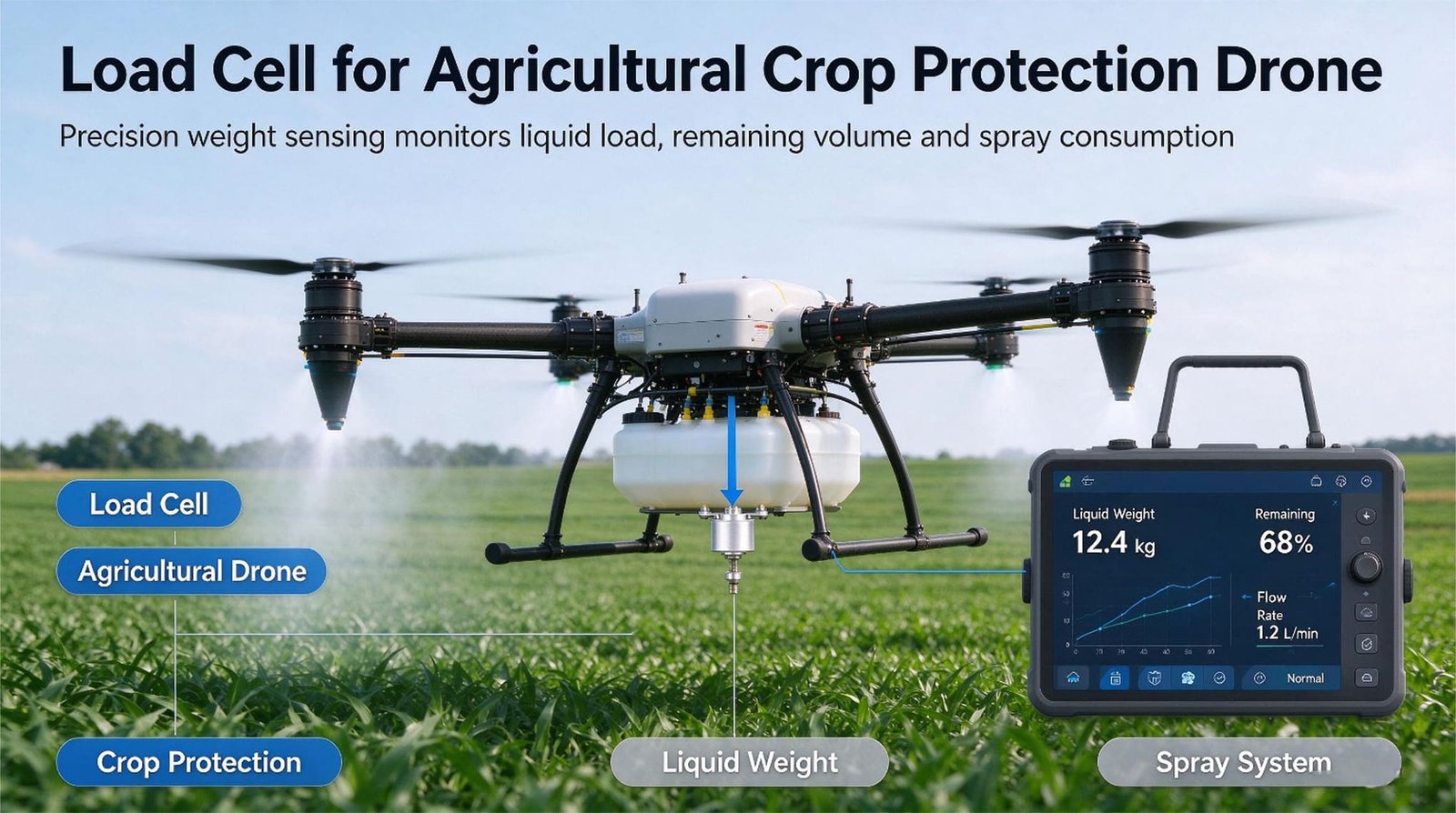
Load Cells for Agricultural Crop Protection Drones
Weighing the spray tank, not the aircraft — and why the load cell is the referee, not the control loop. Sizing arithmetic, aliasing traps, a phantom 0.4 L, and two requests I told customers not to buy.
Export Sales Engineer
VektorForce · Xi’an, China
7 October 2026
12 min read
- 0.05 % FS is not 0.05 % of your reading. A 30 kg cell gives ±15 g on a 20 kg load. The same 0.05 % on a 100 kg cell gives ±50 g. Oversizing quietly multiplies your error.
- ~42 counts per gram. A 30 kg cell at 1.0 mV/V on 5 V into a 24-bit, ±10 mV front end resolves about 42,000 counts per litre of water. Resolution is never your problem. Everything else is.
- 0.1 g of sideways acceleration = 2 kg on a 20 kg tank. That is 10 % error from a manoeuvre. To hold 1 % you would need < 0.01 g, which no rotorcraft does. Weigh the pass, not the instant.
- 75 Hz and 150 Hz are the enemy. At 10 samples/s, 150 Hz folds onto exactly 0 Hz — a constant offset that looks like liquid that isn’t there. At 80 samples/s it folds to 5 Hz and 10 Hz, inside the flow band.
- K = 2.0, not 1.3. Standard tank practice uses a safety factor of 1.3–1.7. A crop protection drone manoeuvres at up to 2 g, and safe overload is 150 % FS, so the static tank load must sit near 50 % FS. Derive the factor; don’t copy it.
- A 10-second weight window beats a ±3 % flowmeter. A whole-tank before/after weight gives you applied mass to about 0.1 %. A 50 ms window gives you nothing. The cell is the referee, the flowmeter runs the loop.
- Why a spray drone needs a scale at all
- The numbers I run before I pick a cell
- A 0.1 g turn: when the reading is actually true
- The 75 Hz trap: aliasing and the tank that never empties
- Sizing the tank cell — one formula, derived
- Case 1: Brazil, 20 L, and a phantom 0.4 L
- Case 2: a 40 L fleet and a refill pad that found a 6 % bias
- Case 3: the 20 Hz request I turned down
- Mounting: hard shims, not rubber pads
- Wiring and summing: three points in, one box, one A/D
- Surviving the chemistry
- Granules and seed: same problem, different numbers
- Where a load cell is the wrong answer
- What I can supply, and what I can’t
- Load cells I’d put on a crop protection drone
- FAQ
1. Why a spray drone needs a scale at all
An agricultural crop protection drone is a machine that carries a liquid, throws it at a field, and comes back to fill up again. On a mid-size machine that means a 20–50 L tank, a 50–500 µm droplet range, a 4–11 m swath flown about 3 m over the canopy, and a pump moving something between 12 and 46 L/min. A large machine covers 15–20 hectares in an hour around 15 L/ha.
There are three places where weighing belongs on that machine, and they are genuinely different jobs:
- Under the tank — how much is left, and how much actually left the nozzles. This is a mass measurement and it is the only one on the aircraft that is traceable.
- At the refill pad — dosing the concentrate correctly, and knowing the gross weight before take-off. This is a ground measurement, so you can afford to make it good.
- In a test rig — hang the machine and weigh it. The cheapest reliable number in the whole system.
The case for a load cell is not “better than a flowmeter”
A flowmeter is a good instrument. It is fast, it is cheap, and it measures what the pump is pushing. Its problem is that it is unverifiable in the field: it drifts as the impeller wears, the wet parts corrode, thick formulations read differently from water, foam confuses it, and it measures flow through the meter rather than what came out of the atomisers.
A weighing tank does something a flowmeter cannot: it closes the loop on mass. Put the tank on a cell, watch the weight fall, and you have a physical, arithmetic-checkable reference for what the aircraft actually applied. Chinese patent CN207907953U describes exactly this architecture — a load cell module under the chemical barrel, sampling the weight change over a time window to derive the actual flow, comparing that against the flowmeter’s reported flow to derive a correction coefficient, and using the coefficient to correct the applied dose. CN108303148B extends it into the rate formula itself. This is not a new idea and it isn’t mine. It is the established, published reason a spray drone has a scale on it.
The flowmeter tells you when you are spraying. The load cell tells you how much. Run the loop on the first, test its honesty with the second, and never swap them.
The regulatory reason, which is more practical than it sounds
Every jurisdiction that regulates these machines regulates them by mass.
In the United States, the FAA publishes a list of UAS approved under Section 44807, and that list carries an explicit column for approved maximum take-off weight including payload. A DJI Agras T25 is listed at 127.8 lb, a T30 at 171.96 lb, a T50 at 227.07 lb — which converts to 58.0 kg, 78.0 kg and 103.0 kg. A BROUAV D-72L-8 is listed at 324.08 lb, or 147.0 kg. The number on the list is the number you have to stay under, and the only way to know whether you are under it is to weigh the machine. Canada draws a line at 25 kg, above which an agricultural machine needs a special flight operations certificate.
In the European Union, Directive 2009/128/EC, Article 9 prohibits aerial spraying and treats drones as aerial spraying, which is why drone spraying in the EU has existed mostly as narrow national derogations — France, for example, for biological control agents, low-risk products and steep vineyards where ground rigs cannot reach. That is changing. The Commission’s Food & Feed Safety Omnibus, COM(2025) 1021 of 16 December 2025, proposes a new Article 9a that would let Member States exempt certain types of unmanned aircraft from the general prohibition, with the Commission to adopt a delegated act identifying eligible drone types and a 30-month window to do it, and EFSA mandated to write risk-assessment guidance for drone-applied plant protection products. The Council adopted its position on the package in May 2026. Separately, EASA’s PDRA-S01 was adapted to cover plant health spraying — it removed the 25 kg maximum take-off weight limit, kept a 3 m maximum dimension, set a 10 m maximum height, and added conditions aligned with Directive 2009/128/EC. Spain’s AESA published a national version and reported processing 160 agricultural applications with 120 approvals. From the machine side, ISO 23117-1 covers the design and performance verification of spraying systems on unmanned aircraft under 150 kg, ISO 23117-2:2025 defines the horizontal transverse spray distribution test, and a further part is in development for droplet deposition into the canopy.
ISO 23117-1 draws its scope at 150 kg, and it is not an arbitrary line — real machines sit right under it. A DJI Agras T100 has a maximum take-off weight of 149.9 kg. A BROUAV D-72L-8 is approved at 147.0 kg. Both are within three kilograms of a standard boundary, which means both need to know their gross weight accurately on every fill, not once at the factory.
The direction of travel is obvious: drone spraying is being normalised, and normalised spraying means measurable, recordable doses. Which brings me to what I actually do.
We build load cells, force sensors, junction boxes, transmitters and weighing indicators in Xi’an, China. We supply the weighing element. We do not build the aircraft, the flight controller, the pump, the nozzles, the tank, the spray-rate algorithm, or the machine’s approval. Everything below is written from that side of the fence, and section 14 is an explicit list of what I will and won’t claim.
2. The numbers I run before I pick a cell
Every enquiry starts the same way. Before I look at capacity, IP rating or price, I work out what the signal actually looks like in microvolts, because that number tells me immediately whether the customer’s real problem is the sensor or something else entirely.
From millivolts-per-volt to microvolts per gram
A strain gauge cell outputs a small voltage proportional to load: Vout = S × Uexc × (L ÷ Max), where S is rated output in mV/V, Uexc is excitation, L is the load and Max is rated capacity. Run it for the three cells I’d actually put on a crop protection drone:
| Cell | Rated output | Excitation | Full-scale output | nV per gram (30 kg cell) |
|---|---|---|---|---|
| WST101 | 1.0 ± 0.2 mV/V | 5 V | 5 mV | 167 nV/g |
| WST1101 (≤75 kg) | 1.0 mV/V | 5 V | 5 mV | 167 nV/g |
| WST401 (S-type) | 2.0 mV/V | 10 V | 20 mV | 667 nV/g |
Now put a typical 24-bit sigma-delta front end behind it: input range ±10 mV, about 5,000,000 counts, which is roughly 4 nV per count. Against the 167 nV per gram of a 30 kg cell at 1.0 mV/V, that is about 42 counts per gram. One litre of water is about 42,000 counts. A 20 L tank empties through about 840,000 counts.
Nobody’s problem on a spray drone is resolution. The adversary is zero drift, span drift over temperature, mounting-induced error, acceleration while flying, and one arithmetic accident in the sampling chain. Every one of those is covered later in this post. Not one of them is covered by more bits.
The mistake that costs the most money: reading “% FS” as “% of reading”
This is the single most consequential sentence in this article, and I will say it in plain terms:
A load cell’s accuracy percentage is a percentage of its full scale, not of the load you happen to be measuring. Over-sizing a cell multiplies your real error in proportion.
Concretely, with a 0.05 % FS comprehensive error:
| Cell capacity | Error at 0.05 % FS | Working load | Error as % of reading | In millilitres |
|---|---|---|---|---|
| 10 kg | ±5 g | 20 kg (overload) | — | — |
| 30 kg | ±15 g | 20 kg | 0.075 % | 15 mL |
| 50 kg | ±25 g | 20 kg | 0.125 % | 25 mL |
| 100 kg | ±50 g | 20 kg | 0.25 % | 50 mL |
Same accuracy class, same brand, same price band — and the 100 kg cell is 3.3× worse on the application than the 30 kg cell, purely because it is the wrong size. Customers choose the bigger cell “for safety” and then complain the weighing is sloppy. The bigger cell did exactly what it promised.
Which sets up the sizing question properly, because there is a real reason to oversize a cell on a drone — and it turns out to be a completely different reason than “safety margin”. I’ll derive it in section 5.
3. A 0.1 g turn: when the reading is actually true
A load cell does not measure mass. It measures force. On a bench, that force is m × g and you can call it weight. On an aircraft it is this:
Everything except m is noise you did not ask for. And az is not small.
What a rotorcraft actually pulls
| Flight condition | Load factor | Apparent weight of a 20 kg tank | Error if read as mass |
|---|---|---|---|
| Level cruise, pump on | ~1.0 g | 20.0 kg | reference |
| Gentle turn | 1.2–1.5 g | 24–30 kg | 20–50 % |
| Terrain following / headland turn | 1.5–2.0 g | 30–40 kg | 50–100 % |
| Pull-up after a dip | 2–3 g | 40–60 kg | 100–200 % |
Even a modest 0.1 g of lateral acceleration on a 20 kg tank is 2 kg of apparent weight — 10 % of the tank. To hold 1 % accuracy from the instantaneous reading you would need total acceleration below 0.01 g. Nothing with four rotors, a flexible frame and a sloshing liquid does that.
What the peer-reviewed work says
This is not my opinion, and it is worth knowing the published numbers before you promise a customer a figure. Drones 2024, 8(3), 92 — “Quantity Monitor Based on Differential Weighing Sensors for Storage Tank of Agricultural UAV” — builds exactly this: a differential pair of weighing sensors under an agricultural UAV tank, characterised against sensor-intrinsic noise, vibration noise and loading uncertainty. They had to run two filter chains to make it work: Butterworth low-pass plus Kalman plus moving average, and an adaptive LMS stage ahead of Kalman plus moving average.
| UAV state | Average relative error | Maximum relative error |
|---|---|---|
| Static (on the ground) | best case in the study | — |
| Hovering | 0.31 – 0.58 % | 1.24 – 2.74 % |
| In flight | 0.74 – 2.54 % | 1.68 – 10.06 % |
Two things follow. First, an in-flight tank scale is realistically a 1–3 % instrument, not a 0.1 % instrument — and if your board has a single moving average where that study needed an adaptive filter, expect the 2.5 % end of the range. Second, the study identifies where the interference lives, and it is not low frequency. More on that in the next section.
Slosh sits exactly where your control loop lives
A partially filled tank sloshes, and the fundamental slosh mode is not fast. For a tank roughly 400 mm across filled to about 200 mm, the first slosh mode works out to around 1.3 Hz. Attitude commands from the flight controller, and the terrain-following loop, sit in the same 0.5–3 Hz band. So the tank’s liquid is moving for the same reasons the aircraft is, at the same frequency, and both show up on the cell as fake weight.
Two practical consequences. Baffling or open-cell foam in the tank raises the slosh frequency and cuts its amplitude — a scale on a baffled tank behaves noticeably better than on a bare one, and the flight controller likes it too. And your filter corner frequency has to sit below 1 Hz if you want to read liquid mass rather than liquid motion, which is the first clue that a fast loop and a weight reading cannot be the same loop.
Weigh the pass, not the instant. A difference over a whole spray pass, or the tank before and after a mission, is a mass measurement. A difference over 50 milliseconds is a force measurement on an accelerating aircraft, and you should not treat it as anything else.
The corollary: the tank cell cannot see the battery. If you put cells under the landing gear you are weighing 20 kg of airframe plus a 14.7 kg flight battery, and the liquid you care about is a small delta on top of a large number that never changes. Put the cells under the tank if you want liquid. Put one jig scale under the whole machine if you want gross weight. Those are two instruments, not one compromise.
4. The 75 Hz trap: aliasing and the tank that never empties
This is the failure I see most often, it is invisible on a datasheet, and it has cost at least two of my customers a set of pumps. It is not a load cell problem. It is a sampling problem.
Where rotor noise lands
A crop protection drone has four rotors turning a few thousand rpm, and blade-pass harmonics multiply up from there. Across a typical machine, the interference band you actually have to survive starts around 30 Hz and runs past 150 Hz. The Drones study above found the dominant interference at 75 Hz and 150 Hz, which is exactly what blade-pass arithmetic predicts.
Now the uncomfortable part. Whatever your A/D does, it reports the signal folded into the band from zero to half its sample rate. Everything above that band comes back as something else. Run the numbers for the two sample rates our own transmitters offer:
| Sample rate | Nyquist limit | 75 Hz appears as | 150 Hz appears as | What the operator sees |
|---|---|---|---|---|
| 10 sps | 5 Hz | 5 Hz | 0 Hz | A constant offset. The tank never reads empty. |
| 80 sps | 40 Hz | 5 Hz | 10 Hz | A 5–10 Hz wobble that the rate loop chases |
At 10 samples per second, a 150 Hz blade-pass harmonic folds onto exactly 0 Hz. That is not a wobble, it is a DC shift — a fake constant weight added the moment the rotors spin up and subtracted when they stop. Your empty-detection threshold never trips, your dry-run protection never arms, and the operator has no reason to suspect the arithmetic rather than the tank.
Why a faster A/D does not save you
Customers often ask whether a faster board fixes this. Not by itself. Aliasing is not about inadequacy, it is about ordering: you either remove the high-frequency energy before the A/D, or you sample far above it so that the fold lands somewhere harmless and you filter digitally afterwards.
- Option A — analog first. A 2-pole (ideally 4-pole) analog low-pass at around 5–10 Hz ahead of the A/D. Two poles at 5 Hz gives roughly 40 dB of rejection at 75 Hz and 50 dB at 150 Hz. This is the cheap, robust answer.
- Option B — oversample and filter digitally. Sample at least ten times the interference frequency, so 1.5 ksps or faster, then decimate in the controller. Fine, but it moves the work to the customer’s board.
- What does not work: a 10 or 80 sps module with no analog front-end, on an airframe whose noise starts at 30 Hz. That combination is a random-number generator with a display.
One more piece of the puzzle, because it explains why you cannot hope the sensor’s own mechanics will handle it. A small strain gauge cell’s first natural frequency is up in the low kilohertz. At 75 Hz you are far below resonance, so the cell’s response is flat and the vibration passes straight through as a genuine force. The cell is not filtering anything for you, and it was never designed to.
Anti-alias in analog, average in digital. Analog low-pass at 5–10 Hz, then sample at 80 sps, then average over 5-second windows for anything you intend to call a flow rate. That chain is cheap, and it is the difference between a 1 % instrument and a 3 % one.
5. Sizing the tank cell — one formula, derived
Now back to the apparent contradiction. Section 2 said oversizing multiplies your error. Section 3 said a drone hits 2 g. Both are true, and the resolution is that you need to oversize deliberately and by a derived amount, not by a habit.
What standard tank practice does
For an ordinary vessel, our own tank and hopper module guidance uses this:
where N is the number of support legs — which is also the number of cells, one per leg — and K is a safety factor covering static versus dynamic load, vibration, uneven load sharing and impact. Standard values are K = 1.3 for three legs, 1.5 for four, 1.7 for six or eight, rising to K = 2 when the tare is more than about half the total weight, because a large tare usually means motors, agitators or jackets that load the legs unevenly. Then round up to whatever the closest stock capacity happens to be, and after installation verify the load sharing by eye and by measuring each cell’s millivolt output.
That is all sound, and for a mixer or a hopper it is what I’d use. For a spray drone I change one number.
Why K = 2.0 on a drone, derived from the overload rating
Work it backwards from what the cell can survive rather than forwards from what looks safe:
- A crop protection drone under terrain-following or a headland turn pulls up to 2 g (section 3). So the peak force on a cell is about twice the static load.
- The cells in our agricultural range have a safe overload of 150 % FS (and 150–200 % ultimate). That is the number the mechanical design is validated against.
- If the static tank load sat at 75 % FS, then 2 g would land exactly on the safe-overload limit — zero margin for a gust, a hard landing, or a slightly uneven leg load.
- Put the static load at 50 % FS instead, and 2 g reaches 100 % FS with the remaining 50 % of capacity held in reserve for transients.
Size the tank cells so the full tank sits at about 40–50 % of rated capacity — that is K = 2.0. Note that this is not a safety margin. It is an accuracy decision that happens to also be a safety decision: at 40–50 % FS a 0.05 % FS cell gives you 0.1–0.125 % of reading, and the same cell survives the manoeuvre envelope. Two birds, one capacity.
Worked sizes for real tank volumes
Tare here means the empty tank plus brackets, straps, strainer and the plumbing that hangs off it — roughly 2.5 kg on a 20 L machine, 7 kg on a 75 L machine. Payload is the liquid at 1 kg/L.
| Tank | Tare + liquid | Cells (N) | Load per leg | Need ≥ | Pick | Static %FS |
|---|---|---|---|---|---|---|
| 20 L | 2.5 + 20 = 22.5 kg | 3 | 7.5 kg | 15.0 kg | WST101 30 kg | 25 % |
| 40 L | 4.0 + 40 = 44.0 kg | 3 | 14.7 kg | 29.3 kg | WST101 30 kg | 49 % |
| 40 L, cell in the drift zone | 4.0 + 40 = 44.0 kg | 3 | 14.7 kg | 29.3 kg | WST1101 30 kg | 49 % |
| 75 L | 7.0 + 75 = 82.0 kg | 4 | 20.5 kg | 41.0 kg | WST101 50 kg | 41 % |
| 75 L, three-leg frame | 7.0 + 75 = 82.0 kg | 3 | 27.3 kg | 54.7 kg | WST1101 75 kg | 36 % |
Note how often WST101 30 kg comes up: it is the same part for both a 20 L and a 40 L tank. That is not an accident of the table — WST101’s stock sizes step 5, 10, 30, 50, 100, 200 kg, so 30 kg is the first capacity above the 15–29 kg window that 20–40 L tanks need. One part number covering the two biggest volume classes in the market is a real supply-chain advantage, and it is worth designing around.
Three points or four? On an airframe, three
This is the other question that decides the build. A three-point suspension is statically determinate: the load at each leg is fixed by geometry alone, no matter how much the carbon frame flexes under manoeuvre. A four-point suspension on a flexible frame is indeterminate — the frame’s deflection decides how the load splits, and if one corner is a little softer the other three carry it. On a rigid ground pad, four points and a junction box are perfect. On a flexing airframe, three.
A base-station pad is a rigid plate, so four cells are fine and the arithmetic is the same K = 2 rule. Tie it to the machine’s published gross weight:
- 58 kg gross (a 25 L class machine, e.g. an airframe approved at 127.8 lb) → 4 × WST1101 30 kg, static 48 % FS
- 103 kg gross (a 40 L class machine, e.g. 227.07 lb) → 4 × WST1101 75 kg, static 34 % FS
- 150 kg class → 4 × WST1101 150 kg for headroom against the drop when the machine lands
6. Case 1: Brazil, 20 L, and a phantom 0.4 L
An OEM in Paraná building a 20 L electric sprayer, about 300 machines a year, came to us in 2024 with a clear plan: delete the flowmeter. Two reasons. Cost, and a corrosion problem in the meter’s wetted parts that was generating warranty claims on machines working with copper-based and sulfur-based products.
I sized the tank side of it: 3 × WST101 30 kg under the tank foot, 5 V excitation, all three into one junction box, output to his board. I also told him the thing he didn’t want to hear — that I did not think he could close a fast rate loop on weight, and that the cell was better used as a check on the meter he was trying to delete. He wanted to try anyway, which is a normal and reasonable thing for an engineer to want. So we shipped, and I asked him one question: what are you sampling at?
He was using our WST1508 transmitter, which was a sensible pick for other reasons — 4–20 mA and 0–10 V outputs, isolated RS-485 Modbus, and a DC 18–35 V supply that runs directly off his 6S pack rail. Its A/D offers 10 or 80 samples per second. He had left it at 10 sps, because 10 sps is the default and nothing on the first page of a datasheet tells you not to.
The symptom
The tank read roughly 0.4 L of residual liquid as soon as the rotors spun up, and the number only went away when they stopped. So the “empty” threshold never tripped, the dry-run protection never armed, and he ran two pump sets dry before he worked out that the liquid was imaginary.
Convert the 0.4 L into signal and it is not subtle. A 30 kg cell at 1.0 mV/V on 5 V gives 167 nV per gram; 400 g is about 67 µV. Against a ±10 mV input window that is 1.34 % of full scale, or 400 g on a 30 kg cell. A large, stable, entirely fictional DC offset.
Where it came from is section 4: 150 Hz sampled at 10 sps folds onto exactly 0 Hz. The blade-pass harmonic of his rotors was being added to his weight reading as a constant. On a bench it was invisible; in the air it was a permanent 0.4 L.
Our transmitter’s 10 sps default is the wrong default for a vibrating airframe, and our datasheet does not shout it. The 80 sps option was there and we sold the part without asking the question that would have surfaced it. We now ask every drone customer what their rotor frequencies are before we recommend a sampling rate, and I would rather write that down than pretend the customer broke it.
The fix, in three changes
- Analog low-pass ahead of the A/D. A 2-pole filter cornered at 5 Hz, placed before the converter rather than in firmware, because software cannot un-fold what the sampler already folded. That alone took the phantom away.
- Run 80 sps and average over 5-second windows for anything used as a rate. With the fold moved out of the way, the 80 sps data is clean enough that a 5-second mean is a real measurement.
- A take-off tare in a steady hover. With the pump off and the aircraft holding station, the tank is in the one state where it is genuinely in equilibrium and you also know the fill volume independently. Re-zero there. It cost him ten seconds per flight and it removes the day’s accumulated drift as well as the offset.
The result: residual read within about ±0.05 L against a graduated fill check, and total applied mass per pass agreed with his flowmeter to roughly 1 %. Which is about the best an in-flight tank scale does, and matches the published 0.7–2.5 % range for a properly filtered system.
And the ending he didn’t want: he kept the flowmeter. It runs the rate loop; the weight reading referees it. He now logs both, and when they disagree by more than 3 % the machine gets pulled out of service for a look. That is what a redundant measurement is actually for, and it is worth more than the flowmeter he thought he was going to delete.
7. Case 2: a 40 L fleet and a refill pad that found a 6 % bias
The second customer was not a manufacturer at all. A contract spraying operator in the Mekong Delta, six 40 L machines, three pilots, working rice and durian. His problem was not flying. His problem was the conversation at the end of the day.
He billed by hectare and by tank. Clients occasionally pushed back — they thought a block had been under-sprayed, or they wanted to know how much product had gone onto a particular field. He had nothing independent to show them except the machine’s own reported figure, which came from the same flowmeter the client was implicitly doubting. Arguing about a number with the instrument that produced the number is not a strong position.
What we built
A refill pad: a 1,200 × 1,200 mm anodised aluminium plate on 4 × WST1101 75 kg, four cells into a WST1513 stainless junction box, into a WST1502 indicator with HI/OK/LO setpoints and an isolated RS-485 Modbus output. Plus two unglamorous accessories that mattered more than the electronics: a hose strain relief so the fill hose doesn’t pull on the plate while it is dosing, and a drip tray so neat concentrate doesn’t sit on the cells.
Total bill of materials, three figures in US dollars, not four. That is worth saying plainly, because the reflex assumption is that weighing instrumentation on agricultural equipment is expensive. A ground pad is the cheapest place in the whole system to buy accuracy.
Two things I insisted on before he ran anything
- A poured, spirit-levelled concrete apron under the pad. There is a striking result in the load cell literature on pre-flight weighing: on a low-cost multi-cell platform, tilting the platform by 3°, 6° and 9° produced statistically significant errors in computed centre of gravity on every payload-and-angle combination tested, reaching 32 mm at 6°/200 g. And the part that matters — applying trigonometric correction barely helped, because the dominant error was the mechanical mounting response, not the geometry. Level the pad physically. Do not try to fix a tilt in the maths.
- Verify the load sharing after installation by measuring each cell’s millivolt output, not just by looking at the four corners. This is standard practice for any multi-cell vessel, and it is the difference between a pad and four cells that happen to share a plate.
What the pad found in the first week
His applied mass, measured by weight, was running about 6 % higher than the figure his flowmeter-based controller was reporting. Same flights, same product, same volumes.
The cause took a while to surface: the pump had been replaced some months earlier with a non-original impeller, and the replacement’s vane geometry differed enough that the flowmeter’s K factor was wrong. He had been under-applying by about 6 % for months — and, trying to make the results look right, he had been raising the mix concentration. That is the part that worries me. Missed dose is a cost problem; over-concentration is a phytotoxicity risk and a residue question, and those are the wrong risks to take on a hunch.
He recomputed the K factor from the pad’s mass figures, reset the controller, and the two now agree to roughly 1 %. This is precisely the architecture the Chinese patent literature describes: use the weighing element to derive the actual flow over a window, compare it with the meter, get a correction coefficient, and correct the dose. The scale did not replace the meter. It calibrated it.
The side effect that paid for the pad
One morning the pad flagged one machine as having applied 9 % less mass than expected for the flight time. The flowmeter said everything was normal. A nozzle filter was part-blocked and the pump was partly recirculating through the relief. Half the swath was getting roughly the right rate and the other half was getting almost nothing — a classic pattern that a single total-flow meter cannot see, and a pattern that shows up in a client’s yield data six weeks later.
He found it before the client did. That, not the dosing, is what he now says the pad is for.
On full tanks with a 14 kg flight battery aboard, he was within about 3 kg of his airframe’s approved maximum take-off weight. He only knew that because he could now put the machine on a scale. Considering that the FAA’s exemption list publishes an approved MTOW including payload for each model, and that the EU’s EASA framework and ISO 23117-1 both draw machine-level lines, being able to produce that number on demand is not a nice-to-have. It is the difference between an operator who knows and one who assumes.
Would I recommend a pad as a first purchase for a one-machine operator? No, and I said so. He bought it after a dispute with a client, which in my experience is the usual trigger for this kind of spending — not the desire for better data, but the desire to end an argument with a number nobody can dispute.
8. Case 3: the 20 Hz request I turned down
The third customer was a European OEM building a 30 L machine for steep vineyards, and he asked us for a load cell to run his spray-rate control loop at 20 Hz.
I said no, and I gave him the arithmetic rather than an opinion. Twenty hertz is a 50 millisecond window. At 20 L/min total flow that is 333 g/s, so a 50 ms window contains 16.7 g of liquid. His reading noise is around 15 g and the airframe is adding one to three percent of manoeuvre acceleration on top. The controller would be chasing its own noise, and what he would end up building is an oscillator with a nozzle on it.
The framing I gave him is the one I use for all of these: the flowmeter’s ±3 % is a systematic error and it is fast and stable. A load cell’s 1–3 % is a random error and it is slow. Those two are not interchangeable — they are complementary. A control loop wants a fast, stable, slightly wrong signal, because it integrates out the bias. A verification instrument wants a slow, accurate, independently traceable signal. Put them in each other’s jobs and both fail.
He bought a better flowmeter for the loop. Then he asked a second question, and I turned that one down too: could we put a load cell under the granule hopper to detect when it ran out of material? No. He already had a contact-resistance material sensor specified. A load cell there costs about ten times as much, needs a protected pocket and a stop, and would tell him nothing the cheap sensor doesn’t. Use a load cell for granules when you need the applied mass record — which he didn’t, because his machine logs area, not mass.
What he did buy: the hang-weighing jig
He took one thing, and it is the simplest useful weighing device on any agricultural drone programme. A jig that suspends the entire machine from a single WST401 S-type cell in tension — 2.0 mV/V, ±0.02–0.05 % FS comprehensive error, mounted in a frame with a swivel so the load stays axial.
Weigh the loaded machine before the first flight of the day and after the last. Two numbers. The difference is the applied mass for the mission, with no dependence on anything electrical inside the tank, and it takes about ninety seconds. At roughly 200 kg on a 500 kg cell, the 0.02–0.05 % FS comprehensive error is 40 to 100 g — under 0.1 % of reading. That is better than anything else in the system, and it costs less than the pad.
- S-types read tension as positive by default. A hanging jig is correct out of the box. If someone builds it as a compression stand — machine on a platform pushing down on the cell — the sign comes out backwards, and the fix is to swap the two signal wires rather than to invert a number in firmware.
- Use a swivel or a spherical seat. S-types tolerate side load and offset load better than most geometries, which is exactly why they get used here, but a jig that pulls off-axis is a jig that lies. The accessory range exists for a reason.
- Know the overload numbers before you suspend anything. Safe overload 150 % FS, ultimate 200 %. A careful lift is fine; a shock-loaded drop into the sling is not, and an S-type with a bent body shows you nothing on the outside.
- This is a workshop instrument, not an onboard one. It needs a level floor, a fixed frame and a person who does the same thing every time. Its accuracy comes from the routine as much as from the cell.
Two of the three things that customer asked me for, I told him not to buy. That is the job. A sensor salesman who never says no is a man you should not buy sensors from.
9. Mounting: hard shims, not rubber pads
The reflex answer to rotor vibration is a rubber pad under the cell. It is almost always the wrong answer, and the arithmetic for why takes one line.
A compliant mount is a spring-mass system. Its natural frequency follows the classic relation fn = (1 / 2π) √(g / δ), where δ is the static deflection of the mount under load. Run it for realistic pad thicknesses:
| Static deflection | What it is in practice | Mount natural frequency | Verdict |
|---|---|---|---|
| 5 mm | a soft rubber pad | 7.1 Hz | Sits on top of your slosh and manoeuvre band. Amplifies it. |
| 2 mm | a firm rubber pad | 11.1 Hz | Still inside the range you care about |
| 1 mm | a thin hard pad | 15.8 Hz | Marginally acceptable, still coupling |
| 0.3 mm | a machined shim | 28.8 Hz | Above the manoeuvre band. Usable. |
| 0.1 mm | essentially solid | 49.9 Hz | Effectively rigid |
Attitude motion and slosh live at 0.5–3 Hz. A 5 mm rubber pad puts a 7 Hz resonance right next to them. Near resonance the mount responds with more motion than the input, so the tank moves further relative to the frame, the liquid sloshes harder, and your weight reading gets worse — while the vibration at 75 Hz that you were trying to kill is still passing straight through, because 75 Hz is well above the pad’s corner. You made the low-frequency problem worse and left the high-frequency problem untouched.
To get a mount natural frequency above 30 Hz you can only afford about 0.3 mm of static deflection. That is not a rubber pad. That is a machined shim. So: mount hard, and filter electronically. If you have to use an elastomer for shock protection, know its deflection, compute its natural frequency, and do not pretend it is a vibration cure.
Stops, hoses and drips — the three things that decide whether it survives
- Mechanical stops. A landing at 1.5 m/s brought to rest in 10 mm is about 11.5 g; in 5 mm it is about 23 g. No load cell rated at 150 % safe overload survives that. Give the tank a positive stop that takes the load before the cell does — set the gap so it engages above your maximum manoeuvre load but below the cell’s safe overload, and make the stop a load path into the frame, never into the cell.
- Hoses are force paths. The suction line from tank to pump is a mechanical connection into your measurement. A 12 L/min pump with a stiff hose pulling 50 g on the tank is 0.25 % of a 20 kg tank — and because it varies with pump loading it is a systematic, load-dependent error, which is the worst kind. Strain-relieve every hose to the frame with a service loop. Never let a hose terminate on the tank.
- Drip loops and drip paths. Our micro cells come with a 200 mm PVC lead and no gland. Our own agricultural machinery guidance is explicit that farm equipment wants PU or PTFE cable rated −40 to +70 °C, and sealed gauges. If the harness is yours, fine — but leave a drip loop below the cell so chemical runs off the cable instead of tracking down it and into the gauge area.
10. Wiring and summing: three points in, one box, one A/D
A three-point tank suspension means three cells, and three cells in parallel is not a compromise — it is the correct way to do it, provided you understand the rules. If you want the full step-by-step on junction box wiring and trimming, we wrote a separate junction box wiring and adjustment guide; what follows is the drone-specific version.
When summing is legitimate, and when it is a mistake
Legitimate: one rigid platform, one load, one load path, one excitation supply. Three or four cells sharing a single tank frame and a single junction box measure one weight, and summing them is exactly right. The physics is friendly: connecting N cells in parallel leaves the combined sensitivity unchanged and multiplies the capacity by N, because each cell contributes its own millivolts per volt and they all divide the same load.
A mistake: summing two genuinely independent weighing channels. If your machine has a tank and a separate hopper, or a tank plus a load cell under the landing gear, those are two measurements. Put them in the same junction box and you get one meaningless number and no diagnostics. One box per rigid body.
The matching rule you cannot skip
Our agricultural guidance has always said that cells sharing a vessel must be the same model, same capacity, same accuracy class and same sensitivity. On the drone it matters more than on a hopper. Look at what our two candidate cells actually promise:
| Property | WST101 | WST1101 |
|---|---|---|
| Rated output | 1.0 ± 0.2 mV/V (±20 %) | 1.0 mV/V, matched output |
| Zero balance | ±0.3 mV/V | ±0.05 mV/V |
| Input / output resistance | not published on the sheet | 1090 ± 30 Ω / 1000 ± 10 Ω |
| Three in parallel | sensitivity spread needs trimming | 363 Ω in / 333 Ω out |
| Four in parallel | sensitivity spread needs trimming | 272 Ω in / 250 Ω out |
| Corner adjustment needed? | yes, unless you match them yourself | no — that is the point of the geometry |
The ±20 % sensitivity tolerance on WST101 is real and it is normal for a low-cost flat cell. It means that three unmatched WST101s in one junction box will not sum to a clean number — one leg will read 0.85 mV/V, another 1.15 mV/V, and an unevenly loaded tank will give you an unevenly weighted average. You have two options: buy matched cells, or trim each channel with the potentiometers in the junction box, which is what the trimmers are for. Do not skip both and then blame the sensor.
Planar beam cells are built for exactly this constraint. WST1101 is an anodised aluminium planar beam with matched output and low profile, and its geometry means three or four of them in a set do not need corner adjustment — which is a large deal when the pad is being assembled in a workshop rather than a metrology lab. That single property is why WST1101 is the cell I put under a refill plate.
Three WST1101s in parallel present 363 Ω and four present 272 Ω on the bridge input. That is a heavier current draw than a single 350 Ω cell, and plenty of transmitters that happily drive “4 × 350 Ω” will be working harder than the datasheet implies. Our WST1502 indicator drives 4 × 350 Ω or 8 × 700 Ω cells, which covers a four-cell pad, but check the numbers rather than assuming. Also: keep the excitation low. At 2.0 mV/V on 10 V you are asking for 20 mV and self-heating the bridge for no reason — 5 V is usually enough and it is kind to the cell.
Wires, signs and interfaces on a flying machine
- Four-wire versus six-wire. Over a 200 mm lead it makes no measurable difference. On a large ground pad with six metres of cable it does: lead resistance sits in series with a 350–1000 Ω bridge and quietly eats span. Use six-wire (sense) or accept the error and calibrate it out.
- Get the sign convention right before you write firmware. S-types read tension positive by default, so a hanging jig is correct out of the box and a compression stand is inverted — fix it by swapping the two signal wires, not by a minus sign buried in a config file that the next engineer won’t find.
- Interface choice depends on where the box lives. A 4–20 mA loop is excellent for the refill pad. An airborne module should speak RS-485/Modbus or hand raw mV/V to the flight controller’s own converter, because the flight controller already has a good A/D and you don’t want two conversions in series. Our WST1508 transmitter runs on DC 18–35 V, which is worth noting because a 6S pack rail sits at 21–25.2 V — inside the window. Our WST1502 indicator with HI/OK/LO setpoints and RS-485 is a ground station instrument, not an airborne one.
- Shielding and grounding. Brushless motor drive and switching pumps are electrically noisy. Shielded cable, single-point ground, signal wiring kept away from phase wires. It is boring and it is free.
11. Surviving the chemistry
This is the part of the selection that gets the least attention and causes the most field failures. A load cell that is perfectly sized and beautifully filtered will still be dead in a year if it is sitting in a drip path of alkaline suspension concentrate.
What farm machinery actually demands
Our own agricultural machinery guidance is stricter than most customers expect, and it is worth reading before choosing a cell. For equipment in the field it asks for: temperature compensation down toward −30 °C; IP68 ingress protection; a body material chosen for chemical exposure, with stainless (17-4PH) where there is corrosive working conditions; a range chosen larger than the actual load because farm equipment shakes and impacts; PU or PTFE cable rated −40 to +70 °C rather than plain PVC; sealed strain gauges with industrial-grade filling compounds; and, because agricultural machinery geometry is complex, a high proportion of custom builds rather than catalogue parts.
Now hold that next to what our standard cells actually publish:
| Specification | WST101 | WST1101 | WST401 |
|---|---|---|---|
| Body material | alloy steel | anodised aluminium | alloy steel |
| Ingress protection | not stated on the sheet | IP65 | IP65 |
| Compensated / operating range | −10 to +40 °C | −10 to +40 °C comp. / −20 to +60 °C op. | −20 to +65 °C |
| Temp. effect on zero | ±0.1 % FS / 10 °C | ±0.05 % FS / 10 °C | ±0.02 % FS / 10 °C |
| Temp. effect on span | ±0.1 % FS / 10 °C | ±0.05 % FS / 10 °C | ±0.02 % FS / 10 °C |
| Safe / ultimate overload | — / 150 % FS | 150 % / 200 % FS | 150 % / 200 % FS |
| Cable as supplied | Φ8 × 200 mm PVC lead | 4-core PVC, 600 mm | 4-wire shielded, 3 m |
Read that table against the agricultural requirement and the answer is unavoidable: our catalogue cells are a starting point, not a finished answer, for anything sitting in the spray path.
- IP65 is water jets, not chemistry. It says nothing about an alkaline suspension concentrate.
- Anodising is not a barrier to strong alkali. An anodised aluminium body is fine in the dry, shaded bay and it is not fine in a drip path.
- WST101 has no IP rating on the datasheet at all and an operating floor of −10 °C. Its temperature coefficients are five times looser than WST401’s. It is the right cell for a protected pocket on a warm machine, and the wrong cell for a cold-climate machine or an exposed position.
- If the cell must live in the wet, it should be stainless and IP68 with a sealed cable — and that is a custom build, which is exactly why our own agricultural material says most farm machinery load cells end up custom.
Six rules I give every crop protection customer
- Move the cell out of the drift zone. A sealed pocket with a labyrinth and a drain hole beats any coating. The nozzles throw 50–500 µm droplets that go everywhere; assume the cell will see mist.
- Choose the cell on temperature before you choose it on accuracy. If your machines work early mornings at −20 °C, WST101’s −10 °C floor has already ruled itself out, and its ±0.1 % FS/10 °C zero drift on a 30 kg cell is 30 g per 10 °C — which is 0.15 % of a 20 kg load. In a black bay under a canopy on a 40 °C day, that is your whole error budget spent before the aircraft takes off.
- Design for washdown. The operator rinses the whole machine after a mission. Water jets, alkaline detergent, and cold water on a hot cell. If it cannot take that, it dies at month fourteen and everyone blames the sensor.
- Fit a drip loop below the cell so chemical runs off the cable instead of tracking into the gauge area. Trivial to add at design time, impossible to add after the potting is done.
- Remember the tank moves. HDPE tanks do not creep much, but they do expand with temperature, and a tank strapped to a cell changes its preload as the sun comes up. Tare before every mission, not once a season.
- Match the cell to the product, not to the label. Many formulations are not water. Surfactants, oils and suspension concentrates change density, and foam on a fresh fill is air that a level sensor believes and a scale does not. Mass is the honest quantity; volume is the label’s quantity. Carry a density table in the controller and use the scale for the truth.
12. Granules and seed: same problem, different numbers
Half of these machines spread dry product as well as spray liquid, and the spreader side is a different design problem with the same sensor. The headline numbers are brutal: a large spreader runs a 115–150 L container and throws material at up to 300–400 kg/min, with a spread width around 9–10 m.
400 kg/min is 6.7 kg per second. A 40 kg hopper empties in six seconds. Once you have that number in your head, the design changes:
- You are not measuring a rate, you are measuring a total. At 6.7 kg/s no load cell is going to give you a clean instantaneous rate — and you don’t need one, because the feeder already controls the rate. What you need from the scale is the total and a fast, reliable empty. The total is what you bill and what you record.
- Volumetric feeders lie, and they lie unevenly. A screw or auger delivers a volume rate. The mass rate depends on bulk density, which depends on granule size, which depends on the batch, and on moisture, which changes across a morning as humidity moves. Wet fertilizer cakes. A scale is the only way to know what you actually spread — and the official test method for spreaders agrees, defining spread-amount accuracy as the weight difference of the hopper contents before and after, measured on a scale.
- Impact is worse here than on the liquid side. The hopper gate and the falling material load the cell dynamically on every pass. With 150 % safe overload, the positive stop and the K = 2.0 rule matter more, not less. And a hopper is heavier than a tank of the same volume when full of fertilizer, so re-run the sizing arithmetic with the real bulk density rather than assuming 1 kg/L.
- Dust gets everywhere, including into the gauge area and the connector. Dry product dust is abrasive and slightly hygroscopic. Enclosure, again — and a connector that a field technician can actually unplug without destroying it.
- And the cheap alternative is often correct. For “has the hopper run out”, a contact-resistance or optical full-empty sensor is the right tool and it costs a fraction of a cell. Weigh the hopper when you need the applied mass record. If nobody is going to write that record down, don’t buy the scale — and I have told customers exactly that.
13. Where a load cell is the wrong answer
I sell load cells, so this section is against my own interest, which is exactly why it belongs in the article. Five places where the correct advice is to buy something else:
| What the customer asks for | Why it is wrong | What to do instead |
|---|---|---|
| Run the spray rate loop on weight | A 20 Hz loop is a 50 ms window containing 16.7 g, against 15 g of reading noise plus 1–3 % of manoeuvre acceleration. You would build an oscillator. | A good flowmeter for the loop. A load cell to referee it. |
| Boolean “is the tank empty” | A float switch or capacitance level sensor does this for a fraction of the cost and does not care about the airframe. | Buy the cheap sensor. Keep the load cell for the record. |
| Replace a level sensor for volume | A drone tank is a simple shape and level sensors are cheap. A cell only earns its place when you need mass. | Level sensor for volume; a cell when you need applied amount, MTOW, billing or a cross-check. |
| Weigh a granule hopper just to detect “out of material” | Ten times the cost, needs a protected pocket and a stop, and tells you nothing the existing sensor doesn’t. | Contact-resistance or optical material sensor. Add the cell only if you need the mass record. |
| Put a cell anywhere it can’t be mounted properly | Bolted to a flexing frame, pulled by a hose, dripping chemical across the gauge area, with no stop — that is a liability that reports numbers. | Fix the mechanical integration first, or measure on the ground instead. |
And the one people dislike hearing most: do not fit a scale to a machine where nobody will ever look at the number. If no one logs it, calibrates it, or acts on it, you have added a failure mode and a cost to a farming machine and bought nothing. A measurement only pays when somebody downstream uses it — the agronomist reading the applied rate, the operator checking a blocked nozzle, the owner settling a bill. Section 7 is a case study in what happens when somebody actually does.
14. What I can supply, and what I can’t
I would rather be explicit about this than let anyone assume. We are a weighing component supplier. Here is the line, in two columns.
- The load cell, sized to your tank or hopper, your load factor and your temperature range
- Mounting guidance: positive stops, load paths, hose strain relief, drip paths
- The junction box, plus the summing and trimming advice for a 3- or 4-point suspension
- The transmitter or indicator with the interface your controller wants — mV/V, 4–20 mA, 0–10 V, isolated RS-485 Modbus
- Test data: matched outputs so your controller can trust the sum, temperature-compensation figures, and a linearity check at three points
- Custom builds: capacity, geometry, cable, connector, material, IP rating, temperature range
- Straight advice on what not to buy from us — sections 8 and 13 above
- The aircraft, airframe, flight controller, GNSS or RTK
- The pump, valves, nozzles or atomisers, the flowmeter, or the spray-rate control algorithm
- The tank, the hopper, the plumbing or the strainers
- Any machine approval. We do not certify an airframe or an operating authorisation — not EASA SORA or PDRA-S01, not FAA Part 107/137 or Section 44807, not a Transport Canada SFOC, not Brazil’s MAPA/SIPEAGRO registration
- Any plant protection product authorisation. Whether a product is authorised for drone application under EU Regulation 1107/2009 is a question for the registrant and EFSA
- Any machine-level metrology claim. OIML R60 is an element certificate: it says a load cell of that type met a metrological standard. It does not approve a sprayer, a drone or a control loop
- Spray uniformity or deposition performance as measured by ISO 23117-2 and the forthcoming canopy-deposition part — that is the machine, the nozzles and the flight parameters
- HACCP, food-contact materials, operator PPE or drift mitigation
I can make the weighing part of your spray drone better than anything else on it. I can’t make the drone. If that boundary is a problem for your project, I would rather you found out from me now than from a datasheet later.
15. Load cells I’d put on a crop protection drone
Three cells cover the whole story: the tank, the pad, and the hanging measurement. All three are catalogue parts, all three have published test data, and all three can be customised on capacity, cable and connector.
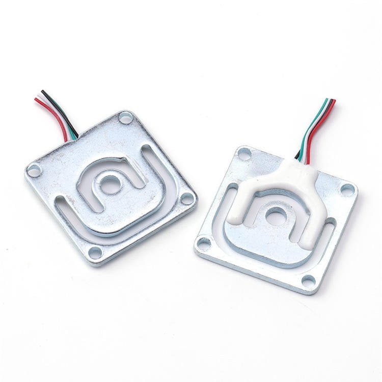
Output: 1.0 ± 0.2 mV/V · 5–10 VDC
Accuracy: 0.05 % FS (linearity, repeatability, hysteresis, creep)
Zero: ±0.3 mV/V · Temp: ±0.1 % FS/10 °C
Body: alloy steel · Φ8 × 200 mm lead
Overload: 150 % FS ultimate
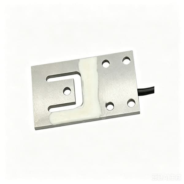
Output: 1.0 mV/V (≤75 kg) · 1.5 mV/V (150–600 kg)
Accuracy: 0.05 % FS comprehensive · 0.02 % repeatability
Zero: ±0.05 mV/V · Temp: ±0.05 % FS/10 °C
Body: anodised aluminium · IP65 · matched output
Bridge: 1090 ±30 Ω in / 1000 ±10 Ω out · 150 % / 200 %
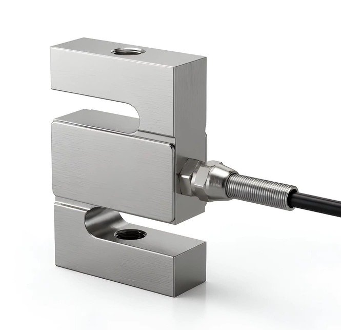
Output: 2.0 mV/V · 10 V recommended
Accuracy: ±0.02 – 0.05 % FS comprehensive
Temp: ±0.02 % FS/10 °C on zero and on span
Body: alloy steel · IP65 · −20 to +65 °C
Bridge: 380 ±10 Ω in / 350 ±3 Ω out · creep 0.02 %/30 min · 150 % / 200 %
Also in the stack, from elsewhere in our range, depending on the build: WST407, an S-type specified for drone and tethered-drone duty with anti-overload protection; WST406, a miniature S-type from 2 to 200 kg when the mounting envelope is tiny; WST1508, a weighing transmitter with 4–20 mA, 0–10 V and isolated RS-485 on DC 18–35 V; and WST1513, a stainless multi-channel junction box.
If your tank, hopper or pad geometry does not fit any of these, that is normal for agricultural machinery — our own guidance says as much. Send me the drawing, the load, the temperature range and the chemistry, and we will cost a custom variant. Related reading from our own blog: tank and silo weighing systems and load cell module selection, weighing on a TMR feed mixer wagon, and how to choose the right load cell for your project.
16. FAQ
Can I run my spray-rate control loop from a load cell instead of a flowmeter?
No, and you should not try. A 20 Hz loop gives you a 50 ms window; at 20 L/min that window contains 16.7 g of liquid, against roughly 15 g of reading noise and one to three percent of manoeuvre acceleration. The controller ends up chasing its own noise. Use a flowmeter for the loop, because its ±3 % is a stable systematic error that a loop integrates out, and use the load cell as the independent referee that keeps the flowmeter honest.
What capacity load cell do I need for a 20 litre spray drone tank?
Three WST101 30 kg cells under a three-point suspension. The arithmetic: 20 kg of liquid plus about 2.5 kg of tank, brackets and plumbing is 22.5 kg total, divided by three legs is 7.5 kg per leg. With a load factor K = 2.0 — because the aircraft manoeuvres at up to 2 g and safe overload is 150 % FS — you need at least 15 kg per leg. WST101 stocks 5, 10, 30, 50, 100 and 200 kg, so 30 kg is the pick, putting the full tank at 25 % FS.
How accurate is in-flight tank weighing on an agricultural drone?
Realistically one to three percent, and the published research agrees: a 2024 study in Drones on a differential weighing system for an agricultural UAV tank reported average relative errors of 0.31–0.58 % hovering and 0.74–2.54 % in flight, with maxima up to 10 %. Those figures came with an adaptive filter plus Kalman plus moving-average chain. On the ground the same hardware is an order of magnitude better: a whole-tank before-and-after weight gives applied mass to roughly 0.1 %.
Why does my tank scale read a phantom amount of liquid as soon as the rotors spin up?
Almost certainly aliasing. If your A/D samples at 10 per second, a 150 Hz blade-pass harmonic folds onto exactly 0 Hz — a constant offset that appears when the rotors start and vanishes when they stop, which the controller reads as liquid. In one case we dealt with, a 0.4 L phantom was about 67 µV on a 30 kg cell at 1.0 mV/V. At 80 samples per second the same interference folds to 5 Hz and 10 Hz instead, which is a wobble rather than a false level. The fix is a 2-pole analog low-pass at 5–10 Hz before the converter, then digital averaging — software cannot un-fold what the sampler already folded.
How many load cells should I use on a spray tank — three or four?
Three on an airframe, four on a rigid ground pad. A three-point suspension is statically determinate, so each leg’s load is fixed by geometry no matter how much the carbon frame flexes. A four-point suspension on a flexible frame is indeterminate: the frame’s deflection decides the split, and if one corner is slightly softer the other three carry it. A refill pad is a rigid plate, so four cells and one junction box are ideal. Either way, use one cell per support leg.
Should I use rubber mounts to isolate the cell from rotor vibration?
Usually not. A compliant mount is a spring-mass system whose natural frequency is (1/2π)√(g/δ). A 5 mm rubber pad puts that frequency at about 7 Hz — right on top of the 0.5–3 Hz band where slosh and attitude motion live — so it amplifies the tank’s motion instead of suppressing it, while the 75 Hz rotor noise passes straight through because it is far above the pad’s corner. To get a mount natural frequency above 30 Hz you can only afford about 0.3 mm of static deflection, which is a machined shim, not a pad. Mount hard and filter electronically. If you must use an elastomer for shock protection, compute its natural frequency first.
Is a load cell or a level sensor better for measuring how much is in the tank?
They answer different questions. A level sensor measures volume and is cheap and simple, but it assumes a density, and it believes foam — freshly refilled tanks with entrained air read high. A load cell measures mass, which is what actually determines the applied dose, the gross weight and the record you can defend to a client. If you only need a low-level warning, a float or capacitance switch is the right purchase. If you need to know how much product went onto a field, you need a scale.
How do I verify the maximum take-off weight of a crop protection drone?
Hang the loaded machine from a single S-type tension cell in a fixed jig — for example a WST401 — and read the gross weight. At about 200 kg on a 500 kg cell the ±0.02–0.05 % FS comprehensive error works out to 40–100 g, under 0.1 % of reading. That matters because approved gross weights are published numbers you have to stay under: the FAA’s Section 44807 exemption list gives an approved maximum take-off weight including payload for each model, ISO 23117-1 draws its scope at 150 kg, and Canada requires a special flight operations certificate above 25 kg.
Do I need IP68 and stainless steel for an agricultural drone load cell?
If the cell sits in the spray path, yes — and that is a custom build, because our catalogue cells are IP65 (or, for the micro flat cells, not IP-rated at all). Our own guidance for agricultural machinery calls for IP68, stainless such as 17-4PH where there is chemical exposure, PU or PTFE cable rated −40 to +70 °C, and sealed gauges. Anodised aluminium is fine in a dry bay and is not fine in a drip path, and IP65 means water jets, not chemistry. The cheapest reliable answer is usually to move the cell out of the drift zone into a sealed pocket with a labyrinth and a drain.
Can I weigh a granule spreader hopper to measure how much I have spread?
Yes, and for spreading it is the only honest measurement, because volumetric feeders deliver a volume rate whose mass rate changes with bulk density and humidity. Note the scale of the numbers though: large spreaders run at 300–400 kg/min, which is up to 6.7 kg per second, so a 40 kg hopper empties in about six seconds. Design for a reliable total and a fast empty signal rather than an instantaneous rate. And if all you need is “has it run out”, a contact-resistance or optical material sensor does that for a tenth of the cost — use a load cell only when you need the applied-mass record.
Tell me the tank or hopper volume, the tare, your operating temperature range, the chemistry, and the rotor or blade-pass frequencies if you know them. I will come back with a capacity, a cell count, a mounting note and a price. If the honest answer is that you don’t need a load cell, I will tell you that too.
Send us your specification →
Email Robin directly