
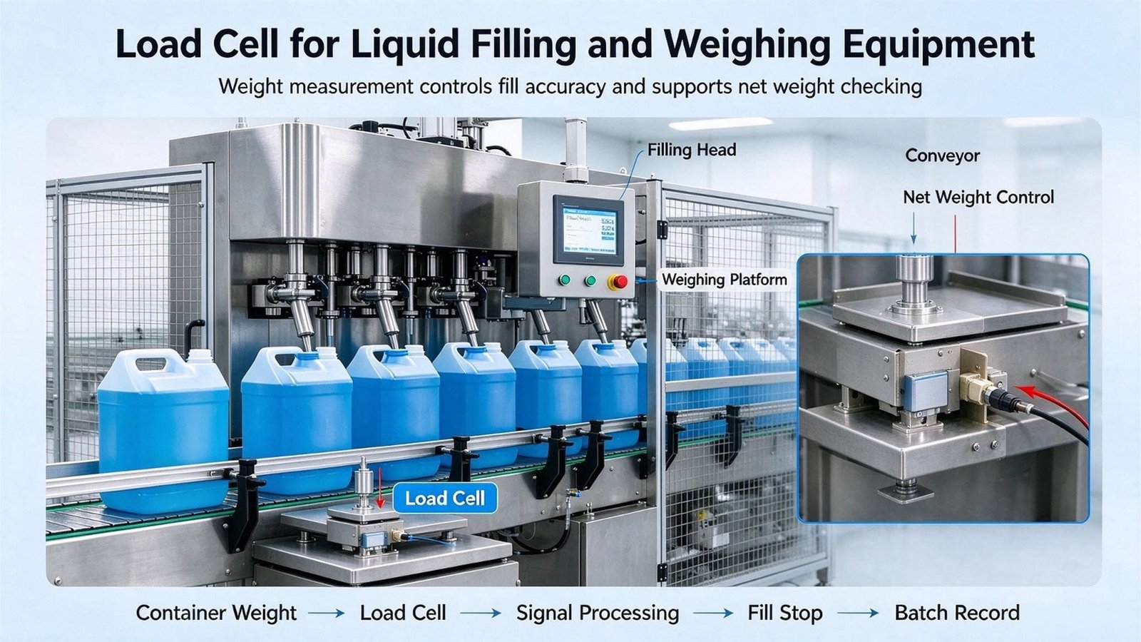
The tolerance that matters is a percentage of the fill, not the capacity.
Load cells for liquid filling machines are usually bought on a number that does not apply to the job. Your legal limit is a percentage of the fill; the data sheet in your hand is a percentage of full scale; and the conversion factor between them — the rated capacity divided by the fill — can turn a comfortable cell into a marginal one without any specification changing. I have spent this year on fillers in Malaysia, the Gulf and southern Europe, and every one of them came down to the same three sentences. Here they are, with the arithmetic.
- A filling machine never weighs the fill you asked for
- The label decides the class, and where my supply stops
- The staircase that sets your tolerance, and the average rule
- The drop, the dribble, and why one speed cannot work
- What a learned advance cannot absorb
- Live tare or preset tare: the decision that sizes your cell
- Case one: the one-litre line that ran heavy every afternoon
- The nozzle, the sleeve and the drip tray
- The settle window, the filter, and the honest answer on sample rate
- Case two: the drum line where I stopped replacing cells
- Sizing: capacity, Vmin, and the multiplier nobody quotes
- Case three: the five-gram sachet line where I said no
- Washdown, IP, and where a supplier’s certificate stops
- Junction boxes, cable and the four-wire question
- The seven parts I would actually quote
- What I ask before I quote, and the routine that keeps the number
- Questions I get asked
1. A filling machine never weighs the fill you asked for
A checkweigher weighs a package that already exists. A filling machine has to create the weight it is weighing, and it can only read the result after the fill has already happened. That single sentence is the whole engineering problem, and it explains almost every strange thing about how these machines are specified.
The consequence is that a filler is not accurate. It is repeatable, and it is accurate only because it has learned to stop early by exactly the right amount. The industry has a word for that early amount. In Chinese it is 落差 (luocha) — literally “the fall”. In English engineering literature it is the drop, the in-flight weight, or the pre-act. It is the mass of liquid that is still travelling between the nozzle and the bottle at the instant the controller decides to close the valve, plus whatever the valve delivers during the time it takes to actually close.
Everything else in this article is downstream of that. If you are buying load cells for liquid filling machines, the number you need to understand is not the accuracy class. It is how much of your error the drop-learning loop can hide, and how much it cannot.
If you want the surrounding picture first — the three weighing jobs that every packaging line needs, from infeed to check to outfeed — I wrote that up separately in Load Cells for Packaging Machinery. This article is the narrow one about the fill itself.
Three ways to put a cell on a filler
Filling-machine instruments sold into this market typically advertise three modes, and it matters which one you are in because the load cell’s job is completely different in each. The wording below is the wording on a Chinese filling controller’s own feature list, translated: single-head additive, multi-head additive, and multi-head subtractive.
| Mode | What the cell actually carries | Typical capacity | Where the accuracy comes from |
|---|---|---|---|
| Additive, single head one platform, one nozzle |
the container plus its contents | 1 to 50 kg | the drop loop, per head |
| Additive, multi head up to 16 platforms on one machine |
the container plus its contents, once per head | 1 to 30 kg per head | the drop loop, per head — and per head means per head |
| Subtractive the supply vessel is on the cells |
the whole supply vessel, full to empty | 100 kg to several tonnes | the difference between two readings of a large mass |
| Net weight on a carrier the container sits in a puck or a tray |
container, product and the carrier together | 1 to 10 kg | the drop loop, but the tare now includes a machine part |
The fourth row is the one people forget to mention at the enquiry. If your bottles ride in stainless pucks so the line can handle odd shapes, then every weighing includes the puck, and the puck has to come back to the same weight every cycle. That is a tare problem, not a load cell problem, and it is worth about as much as everything else in this article.
A filler is the one weighing machine where “repeatable and wrong” is a passing grade. Its whole architecture is built to convert a stable error into a learned constant, and a stable error is exactly what a cheap load cell gives you. That is why fillers reach 0.1 percent with cells that would embarrass a checkweigher — and why the same fillers fall apart the week the product temperature starts moving.
Why the industry fills by weight and not by volume
A volumetric filler dispenses a fixed volume. The label promises a mass. The bridge between them is density, and density moves with temperature. For a light organic liquid such as an edible oil or a lubricant base stock, the volumetric expansion coefficient is roughly 0.0007 per degree Celsius. Over a 15 °C shift from a cold morning to a warm afternoon, the same piston stroke delivers 1.05 percent more mass.
On a one-litre fill that is 10.5 grams, against a 12 gram legal allowance at class X(1). A handful of degrees of ambient change therefore eats nearly the whole allowance of a mechanically perfect filler. Water’s coefficient is about three times smaller, which is why water bottlers get away with volume for far longer than oil packers do; a light hydrocarbon’s is larger again, and there volume has no chance at all.
This is also, incidentally, a change of legal chapter. In the European Union a filler that measures volume is a liquid measuring system under Annex VII of the Measuring Instruments Directive; a filler that measures mass is an automatic gravimetric filling instrument under Annex VIII, chapter III. If you are converting a line from one to the other, you are not upgrading a machine — you are replacing the instrument’s whole regulatory identity, and the two do not share a tolerance table.
1. The average must sit four times tighter than a single fill may wander. Individual fills are treated generously; the mean is not.
2. The current directive and the current international recommendation describe the same class X(1) with different numbers — 0.8 times and 1.0 times the same base — because they measure it at different moments in the machine’s life.
3. Neither of those numbers is a percentage of your load cell’s full scale. Converting between the two is where most of the money is lost and won.
2. The label decides the class, and where my supply stops
The legal name for what we are discussing is an automatic gravimetric filling instrument, abbreviated AGFI. The European definition is worth quoting exactly, because every word in it does work: “an automatic weighing instrument that fills containers with a predetermined and virtually constant mass of product from bulk.”
Note what is missing. There is no requirement that the machine weigh anything the customer can see. Gravimetric describes how the machine decides when to stop, not what it prints. This produces the single most useful boundary test in the whole subject, and it comes from WELMEC’s own guidance rather than from any manufacturer’s brochure.
If the machine prints or stores the actual weight and that figure is used for a regulated purpose — a transaction, a label, a declaration — then it is an automatic catchweigher, and a whole different set of requirements applies to it. If the machine prints the actual weights for management only, and the pack itself carries the nominal weight, then it is a filling instrument. Same hardware, same load cells, same nozzle. The instrument does not decide its own class. The label does.
I have watched a European packer discover this the expensive way: a line built as a filler, with the actual fill weight printed on every carton because the sales team liked the traceability, which quietly reclassified fourteen machines. The tolerance table did not change. The conformity route, the marking, and the paperwork did.
Which chapter of the law you are in
| How the fill is decided | EU | United States | China |
|---|---|---|---|
| By mass, gravimetric filler | MID 2014/32/EU, Annex VIII MI-006, Chapter III | NIST HB 44 §2.24 Automatic Weighing Systems, plus HB 133 for net content | JJG 564-2019 and GB/T 27738-2011 |
| By volume, piston or flow meter | MID Annex VII MI-005, liquid measuring systems | HB 44 §3.30 Liquid-Measuring Devices, or §3.37 Mass Flow Meters | JJG volumetric regulations; not JJG 564 |
| Gravimetric, but you print the actual weight | MI-006 Chapter II, automatic catchweigher | HB 44 §2.24 as a weigh-labeller | Automatic catchweigher regulations |
| Gravimetric, but you run a separate quantity-control programme | Unchanged — MI-006 still applies | HB 44 §2.24 A.2(g) puts the filler outside this code if you determine lot compliance with your own statistical process control and traceable standards | No equivalent exemption |
NIST Handbook 44 §2.24 applies to filling machines that determine package and lot compliance with net content representations, and its exceptions list removes machines used in a plant that has a separate quantity-control programme — statistical process control, suitable weighing instruments, standards traceable to national standards. In plain terms: control net content statistically with traceable equipment and the filler does not have to be a legal-for-trade device. What it does have to be is capable, and the programme has to actually exist on paper.
For completeness, the Chinese pair is JJG 564-2019, the verification regulation that replaced JJG 564-2002 and added the milligram to its units, and GB/T 27738-2011, the product standard, which is currently being revised to adopt OIML R61-1:2017. The Chinese regulation names the same two performance quantities as the international recommendation: the maximum permissible deviation (MPD) and the maximum permissible preset value error (MPSE), and it requires the control instrument used to verify the filler to be better than one third of both.
Two accuracy classes, not one
The directive requires the manufacturer to declare two classes, and this trips up almost every quotation I receive. The reference accuracy class, Ref(x), is the best the instrument type can do, and it applies to static loads. After installation the individual machine is designated one or more operational accuracy classes, X(x), having taken the actual product into account.
The class factor x must be 2 or less and must be of the form 1, 2 or 5 times a power of ten — so 0.2, 0.5, 1 and 2 are the usual working values. X is a regime relating accuracy to load weight, and x is simply a multiplier applied to the limits given for class X(1). A class X(0.5) machine is allowed exactly half of what X(1) is allowed. Nothing else changes.
The static requirement for the reference class is easy to trip over: the maximum permissible error for Ref(x) on static loads is 0.312 of the per-fill deviation limit, multiplied by x. For a 1,000 gram fill at X(1) that is 0.312 times 12 grams, or 3.744 grams — the same figure that appears later as the setting error, and section 3 shows why.
What I supply on a filling machine, and what I refuse to
I want this on the record early, because the boundary is the honest part of the offer. I make the weighing layer. I do not make, certify or approve filling machines, and I have no interest in pretending otherwise.
| I supply | I do not supply, and will not sign for |
|---|---|
| Load cells and force sensors, in C3 and C6 grades, analog and digital | The filling machine, the weigh platform, the indexer, the conveyor |
| Matched sets and matched pairs, with the matching data in writing | Nozzles, valves, pumps, servos, suck-back systems, level sensors |
| Summing junction boxes with per-channel trimming and surge protection | The filling controller’s drop-learning algorithm, or its recipe management |
| Weighing indicators and transmitters, with the excitation and interface data | Certification of the machine, the type approval, or the conformity assessment |
| The load cell’s OIML R60 test data at the component level, and the mounting advice | Anything performing a safety-rated function, and any risk assessment |
| Honest arithmetic on whether the cell is your limiting factor at all | A claim that a component certificate makes your machine compliant. It does not. |
One clarification that saves arguments later. An OIML R60 certificate is a component certificate: it says a cell may be used inside a verified instrument. It is not a machine approval, it does not transfer to the machine, and a filler carrying nothing but R60 test sheets from me has no metrological status at all. The machine’s class is earned by the machine, on the customer’s own product, in the customer’s own hall, by whoever holds the approval. My job is to ensure the cell is never the reason that fails. If you are still choosing between cell types for load cells for liquid filling machines, start with How to choose the right load cell for your project.
3. The staircase that sets your tolerance, and the average rule
Here is the table everything else is built on. It is Table 5 of MI-006 chapter III in the current directive, and it gives the maximum permissible deviation of each fill from the average — not from the target — for class X(1). The other classes are this table multiplied by their own factor.
| Mass of the fill, m | Allowance, class X(1) | Class X(0.5) | Class X(0.2) |
|---|---|---|---|
| m ≤ 50 g | 7.2 % | 3.6 % | 1.44 % |
| 50 g < m ≤ 100 g | 3.6 g | 1.8 g | 0.72 g |
| 100 g < m ≤ 200 g | 3.6 % | 1.8 % | 0.72 % |
| 200 g < m ≤ 300 g | 7.2 g | 3.6 g | 1.44 g |
| 300 g < m ≤ 500 g | 2.4 % | 1.2 % | 0.48 % |
| 500 g < m ≤ 1,000 g | 12 g | 6 g | 2.4 g |
| 1,000 g < m ≤ 10,000 g | 1.2 % — 12 g at 1 kg | 0.6 % — 6 g at 1 kg | 0.24 % — 2.4 g at 1 kg |
| 10,000 g < m ≤ 15,000 g | 120 g | 60 g | 24 g |
| 15,000 g < m | 0.8 % | 0.4 % | 0.16 % |
Read the staircase carefully, because it is not smooth. Between 500 and 1,000 grams the allowance is a flat 12 grams; just above 1,000 grams it becomes a percentage again, so a 1,100 gram fill is allowed 13.2 grams while a 1,000 gram fill was allowed 12. Pack sizes that straddle a band edge can therefore have different compliance difficulty for a 50 gram change in target weight, which is a real effect and not a curiosity.
The average is four times tighter than the individual fill
The per-fill table above is the generous half of the law. The demanding half is the setting error: where a fill weight can be preset, the maximum difference between the preset value and the average mass of the fills is 0.312 of the per-fill allowance. The international recommendation and the Chinese regulation express the same requirement as 0.25 of the in-service allowance. Both roads arrive at the same number.
| Quantity, 1,000 g fill, class X(1) | Value | Source |
|---|---|---|
| Per-fill allowance, directive | 12 g | MI-006 Annex VIII chapter III, Table 5 |
| Per-fill allowance, in-service, international recommendation | 15 g | OIML R61, and JJG 564-2019 for X(1) |
| Per-fill allowance, initial verification, older recommendation | 10.5 g | OIML R61 as transposed into UK law in 2000 |
| Setting error: how far the average may sit from the preset | 3.744 g (directive) / 3.75 g (R61) | 0.312 × 12 g, and 0.25 × 15 g |
| Static requirement for the reference class Ref(x) | 3.744 g | 0.312 × the per-fill allowance |
The apparent disagreement between the two rules is arithmetically empty, and seeing why is worth thirty seconds. The directive’s per-fill allowance is 0.8 times the in-service allowance the recommendation uses — 12 grams against 15. And the directive’s setting-error factor is 1.25 times the recommendation’s factor — 0.312 against 0.25. Multiply those two factors and you get 1.0. 0.312 times 0.8 is 0.25. Both documents are describing one requirement, against two different baselines, and the apparently different numbers are the same number.
On a 1,000 gram fill at class X(1): individual fills may wander 15 grams, but the average must be held within 3.75 grams of the preset. The mean is four times tighter than the scatter. Your drop-learning loop controls the mean and has almost nothing to do with the scatter. That is why a filler can produce a beautiful histogram and still fail verification, and it is why the load cell argument in this article is mostly an argument about slow errors.
The floor under the staircase: rated minimum fill
The deviation table only applies at or above the instrument’s rated minimum fill. Below it, the machine is not out of tolerance; it is outside the scope of its own accuracy claim. The directive makes the manufacturer declare this value. The recommendation builds it from the scale interval and the class, and the resulting staircase is one of the more useful tables in the subject, because it converts a clever purchasing question into a hard floor.
| Scale interval d | Minfill, X(0.2) | Minfill, X(0.5) | Minfill, X(1) | Minfill in divisions, X(1) |
|---|---|---|---|---|
| 0.5 g | 28 g | 11 g | 5.5 g | 11 d |
| 1 g | 111 g | 22 g | 11 g | 11 d |
| 2 g | 334 g | 44 g | 22 g | 11 d |
| 5 g | 1,665 g | 335 g | 110 g | 22 d |
| 10 g | 3,330 g | 1,330 g | 330 g | 33 d |
| 20 g | 6,660 g | 2,660 g | 1,340 g | 67 d |
| 50 g | 25,000 g | 6,650 g | 3,350 g | 67 d |
| 100 g | 50,000 g | 20,000 g | 6,700 g | 67 d |
| 200 g | 100,000 g | 40,000 g | 20,000 g | 100 d |
Those values come from the recommendation’s own certificates of conformity, and they are why a weigh hopper with a 50 gram interval can never certify a 1 kilogram addition at class X(1): the floor is 3,350 grams. The machine is not faulty. It is the wrong machine for that ingredient, and the only fixes are a finer interval, a looser class, or a separate station. In divisions the floor runs from eleven at fine intervals to a hundred at coarse ones.
Two footnotes. First, these floors assume the fill is produced in one weighing; where a fill is made of several loads the floor is higher, because each load has to be large enough to be weighed honestly. Combination weighers take their class from the fill, not from the individual drops. Second, Minfill rises when the environment is bad, and the recommendation names temperature effect on the no-load indication, zero-setting accuracy, disturbances, warm-up time, the product and the interval. Four of those six are environmental, which is why the same platform carries a higher floor beside a vibrating conveyor than on a test bench. The same logic governs process vessels, which is why I keep the three weighing jobs on a vessel separate in Load Cells for Hopper Scales.
Sixty fills, and the instrument you verify with
The average needs statistics. For fills up to 10 kilograms the recommendation requires 60 test fills to establish it; 32 fills for 10 to 25 kilograms, 20 for 25 to 100 kilograms and 10 above that. Sixty consecutive bottles is a real production run, and it is the reason a machine that looks fine over five bottles is not fine.
The instrument used to weigh those 60 fills must be accurate to better than one third of both the MPD and the setting error. A Chinese verification paper works the example through with a 60 kilogram, 20 gram platform as the control scale for a 50 kilogram X(1) machine, and for class X(0.2) the same literature points at balances with more than ten thousand divisions. When a customer tells me his filler has been verified, my first question is what the control instrument was and when it was last verified itself.
One more clause that almost nobody quotes, and it matters if you have variable-frequency drives in the same cabinet. The directive sets the critical change value due to a disturbance as the static error calculated at the rated minimum fill, rounded up to the next scale interval — judged at Minfill, not at maximum capacity. With a one gram interval and an eleven gram floor, that collapses to a single division, which is a real argument for surge protection rather than the cheapest summing box on the market.
The maximum permissible standard deviation for a catchweigher of class X(1) is 0.8 grams at a 1,000 gram load. The filling instrument’s own per-fill allowance is 12 grams. The ratio is exactly fifteen, in every band of both tables. So the instrument that is going to catch your filler drifting must hold its own dispersion to one fifteenth of what the filler is allowed. That is not a design preference; it is the arithmetic of the two tables, and it is why a checkweigher and a filler are never the same scale with a different program.
4. The drop, the dribble, and why one speed cannot work
The drop is the product in the air plus the product delivered during valve closure, and to first order it is a multiplication: the flow rate at the moment of the decision, times the time the valve takes to stop delivering. A machine pouring one litre per second through a pneumatic valve that takes 45 milliseconds to close has a drop of 45 grams — 4.5 percent of a one litre fill, and the reason the valve cannot simply be told to shut at the target.
The trick is to stop the fast fill early and finish the last few percent slowly. On a machine that fills about 85 to 90 percent of the target at full rate and then throttles to a trickle of roughly one twentieth of the fast flow, the same 45 millisecond valve closure produces a drop of 2.25 grams instead of 45. Twenty times smaller. That much everyone in the industry knows.
What fewer people work out is what happens to the scatter of the drop, because the mean is not the problem. If the closing time varies by five milliseconds and the flow varies by five percent, those two uncertainties combine to about twelve percent of the drop. That twelve percent is what the learning loop cannot remove, because it changes from fill to fill.
| 1,000 g fill, class X(1) | Single speed, 1 kg/s | Two stage, dribble at 50 g/s |
|---|---|---|
| Drop at a 45 ms closure | 45 g | 2.25 g |
| Scatter of the drop, ±5 ms and ±5 % | ±5.48 g | ±0.274 g |
| As a share of the 3.744 g setting-error budget | 146 % | 7.3 % |
Read the third row and the whole architecture becomes obvious. At one speed, the scatter of the drop alone is one and a half times the entire legal allowance on the average — before a single load cell error is added, before the product temperature moves, before anything else. No cell on earth rescues that machine. The dribble stage is not a refinement for fussy customers; it is the only reason the number exists at all.
The line speed sets the flow, and the flow sets the drop
Here is the coupling that catches people when they scale a line up. A cycle is not all filling. Indexing, clamping, taring, valve actuation, post-fill settling and verification all take time, and on the machines I have measured that overhead is on the order of 400 milliseconds. Everything left over belongs to the pour.
| Line speed, one head | Cycle time | Time to pour 1,000 g | Flow needed | Drop at 45 ms |
|---|---|---|---|---|
| 40 bottles per minute | 1,500 ms | 1,100 ms | 909 g/s | 41 g |
| 60 bottles per minute | 1,000 ms | 600 ms | 1,667 g/s | 75 g |
| 100 bottles per minute | 600 ms | 200 ms | 5,000 g/s | 225 g |
At 60 bottles per minute on one head the flow has to reach about 1,667 grams per second and the drop becomes 75 grams, whose scatter at that same twelve percent is 9.1 grams — 244 percent of the legal allowance on the average. So a 60-per-minute one-litre line is not a single-head line. More usefully, the same arithmetic sets the dribble stage: throttle to five percent of the fast rate and the drop is 3.75 grams, whose scatter is 0.46 grams, or twelve percent of the allowance.
Because the drop loop is a low-pass filter on the cell’s errors, and it re-learns the constant as often as you let it. A cell that is 30 grams wrong in a stable way is a cell that is 30 grams wrong in a way the loop can absorb. A cell that is 0.5 grams wrong in an unstable way is a cell the loop cannot touch. That is the entire purchasing criterion for this application, and it inverts the usual instinct: buy stability, not accuracy.
One consequence for the machine builder: an adaptive drop loop needs to know when not to learn. Update the constant on every fill and it chases the tail of the distribution and inflates its own scatter, so most controllers learn slowly, or only on fills inside a window, or on a schedule. When a customer’s average is wandering, the first thing I ask for is the machine’s own drop-correction log and the interval at which the loop may update. With no log, the next best thing is to rule the cell out honestly, and I wrote the procedure for that in How to determine whether the load cell is damaged.
5. What a learned advance cannot absorb
A constant error and a drifting error look identical on a data sheet and behave completely differently on a filling line. The rule is short enough to put on a wall: anything constant during the measurement, and constant with respect to whatever reference you last set, cancels. What survives is anything that changes during the measurement, anything that has changed since the reference was set, anything that is not a straight line, and noise.
Applied to each of the three machine types from section 1, that rule sorts the load cell’s specifications into two groups — and the group that survives has one thing in common.
| Load cell imperfection | Additive, live tare every container | Additive, preset tare, zero once per shift | Subtractive, supply vessel |
|---|---|---|---|
| Span or sensitivity error | Reduced to the fill; cancels entirely between tare and gross on the same cell | Lands on the gross, container included | Cancels in the difference of two readings |
| Zero drift, slow | Cancels — both readings share the same zero | Full amount, at full scale | Cancels inside one fill, but not across a shift |
| Non-linearity | The part inside the fill | Lands on the gross | The part inside the increment |
| Repeatability and short-term noise | Survives in full, and it is scaled by full scale | Survives in full | Survives, and two readings make it larger |
| Creep during one fill cycle | Negligible — seconds, not minutes | Negligible | Negligible |
| Creep between re-zeroes | Cancels | Survives | Survives |
| Resolution and division size | Half a division | Half a division | Half a division, twice |
Look at the middle column, which is how most high-speed machines actually work. Three of the seven rows survive in full and all three are expressed as a percentage of the cell’s rated capacity. The bold entries in every column have the same property: they are quantities that nobody re-measures. That is the whole mechanism, and it produces the most useful sentence in this article.
Your legal limit is a percentage of the fill. Your load cell’s repeatability and temperature coefficients are percentages of full scale. The conversion factor between them has a name and a value you can write down in a meeting: rated capacity divided by the fill.
A two percent of full scale figure on a 5 kilogram platform feeding a one kilogram bottle is two tenths of a percent of the bottle. The same figure on a 250 kilogram supply vessel feeding a 5 kilogram pail is one percent of the pail. Same sensor family, same datasheet, five times the consequence.
The rule, worked out
Take our standard analog family, whose repeatability is quoted as ±0.02 %F.S — that is the figure on the WST201, WST216, WST217 and WST202 pages. The cell’s contribution to one fill, in grams, is 0.0002 times the rated capacity. The legal allowance for that fill, in grams, is a percentage of the fill. Divide one by the other and the capacity cancels out of the interesting part:
| Installation | Rated capacity | Fill | Capacity ÷ fill | Cell noise in grams | Share of the class X(1) allowance |
|---|---|---|---|---|---|
| One litre bottle on a 5 kg platform | 5 kg | 1 kg | 5× | 1.0 g | 8.3 % |
| One litre bottle on a 3 kg cell | 3 kg | 1 kg | 3× | 0.6 g | 5.0 % |
| Five litre pail on a 10 kg platform | 10 kg | 5 kg | 2× | 2.0 g | 3.3 % |
| Twenty litre pail on a 30 kg platform | 30 kg | 20 kg | 1.5× | 6.0 g | 2.5 % |
| Five litre pail on a 250 kg supply vessel, subtractive | 250 kg | 5 kg | 50× | 50 g | 83 % |
| Twenty litre pail on the same vessel, subtractive | 250 kg | 20 kg | 12.5× | 50 g | 21 % |
| Five litre pail on a 25 kg metering vessel | 25 kg | 5 kg | 5× | 5 g | 8.3 % |
The pattern is worth stating as a number, because it removes the need for a spreadsheet in most meetings. The cell’s share of the allowance is 1.67 percent of full scale divided by the fill percentage, which simplifies to a single ratio: the cell’s share is about 1.67 percent of the quantity, capacity divided by fill. It reaches one hundred percent — the cell alone eating the entire class — at a capacity-to-fill ratio of 60 for class X(1), 30 for X(0.5) and 12 for X(0.2).
That is the design rule. If your weighing vessel is more than sixty times the fill, an ordinary class C3 cell has already spent the whole per-fill allowance on its own repeatability, before you add the product, the machine or the ambient. Moving the fill onto a 25 kilogram intermediate metering vessel cuts the cell’s share from 83 percent to 8.3 percent — tenfold, achieved with plumbing. A class C6 cell on the big vessel instead halves the error and leaves it at 45 percent. Both are legitimate engineering; only one of them is cheap, and that trade-off runs through nearly every decision about load cells for liquid filling machines.
6. Live tare or preset tare: the decision that sizes your cell
Two machines can have the same valve, the same platform, the same cell and the same product, and need cells of completely different quality, because of one engineering decision taken years earlier and rarely revisited: does the machine weigh the empty container on every cycle?
A live tare costs time — roughly 40 milliseconds on the machines I have measured, which is four percent of a 1,000 millisecond cycle and a much larger fraction of a fast one. A preset tare costs nothing in time: the average container weight is typed in at changeover, and the machine simply subtracts it. What the preset tare costs is everything in the middle column of the table in section 5. Every slow error in the cell, and every variation in the container, now arrives in full at the fill.
How much the container actually varies
| Container | Tare | Spread bottle to bottle | As a share of the fill | Against the prepackage tolerance |
|---|---|---|---|---|
| Blow-moulded PET, 1 litre | about 28 g | ±1.5 g | 0.15 % | 10 % of 15 g |
| Injection-moulded HDPE, 1 litre | about 60 g | ±0.8 g | 0.08 % | 5 % of 15 g |
| Glass, 700 ml | about 400 g | ±8 g within a batch, tens of grams between batches | 1.14 % | 53 % of 15 g |
| Stainless puck or carrier | 300 to 900 g | ±1 g if it is clean, ±5 g with product on it | up to 0.5 % | up to 33 % of 15 g |
The plastic bottles are not the problem, which is worth saying plainly because the instinct is to blame them: a blow-moulded litre bottle varies by a gram and a half, one tenth of the prepackage tolerance on a 1,000 gram fill. The container that hurts is glass. A 700 millilitre glass bottle weighs about 400 grams, and although a single batch is beautifully consistent the spread within a batch is still around eight grams — 1.14 percent of the fill, and more than half the 15 gram tolerance for that size. Fill glass by weight with a preset tare typed in from the last delivery and you have given away half your allowance before the filler does anything. The fix is a bottle-weighing station, a batch tare re-measured at every delivery, or a container supplier who will hold a tighter mass tolerance.
And here is where absolute accuracy comes back into a machine that otherwise does not need it. If you re-measure the tare at every batch, the number you type in is read off a scale, and the error in that one reading applies to every bottle in the batch. A zero offset of 0.05 percent of full scale on a 5 kilogram platform is 2.5 grams, and 2.5 grams of tare error is 2.5 grams on every one of a hundred thousand bottles. Take that reading once a week and it barely matters; take it once a shift and it is the largest single term in your budget. I hit the identical wall on smart LPG cylinders, where the tare has to be assumed for years at a time.
This is the shape of the problem, and it is not the shape people assume. A machine running 60 bottles a minute for sixteen hours makes 57,600 fills a day. For 57,598 of them the machine needs one thing from the load cell: that the same mass produces the same reading. Twice a day — when the tare is established and when the zero is verified — it needs the cell to be absolutely right, because whatever error is in that reading is then applied to every fill that follows.
So the specification you should shop for is not an accuracy class. It is repeatability, zero return after unloading, and the two temperature coefficients — and then, separately, one honest measurement of the cell’s absolute error once per shift with a certified weight, so that the number you type into the controller is actually the weight of the container.
7. Case one: the one-litre line that ran heavy every afternoon
A personal-care contract packer in Malaysia — two heads, 60 bottles a minute, a one litre shampoo-style surfactant product, in PET. The email was short and came with a spreadsheet attached: fills drifted light through the day, about 1.8 grams by four in the afternoon, and back on nominal every morning. The spreadsheet also showed that the operator had been nudging the preset up each afternoon and the QA manager had been nudging it back each night. A machine of theirs had been sold, so the first hypothesis on the factory floor was the load cells.
Whenever I hear “it drifts through the day” I know the culprit is a slow accumulated force, and I know I will be told it is temperature. So I asked for two things before any drawing, and neither of them was a datasheet. I asked for the drop-correction value logged with a timestamp across a full day, and I asked for photographs of the weigh deck and the area under the nozzles at seven in the morning and at four in the afternoon.
First, clear the cell
I asked them to put their certified one kilogram test weight on the platform at the start of the shift and again at the end, with the deck wiped clean both times, and to send me the readings. They came back 0.4 grams apart. On a 5 kilogram cell with a two-hundredths-of-a-percent repeatability — one gram — that is inside the cell’s own noise. The cell was not the problem, and I said so in writing before proposing anything. It is worth the two days it takes, because it converts the conversation from a supplier defending a product into two people reading a log.
Then, read the log
The drop value did exactly what the complaint said. It started each morning at 68 grams, fell steadily to 66 grams by the end of the shift, and reset at the next start — and here is the part that mattered: the machine takes its zero once per shift, at startup, not per bottle. A live tare would have cost it 40 milliseconds of a two-second cycle and the machine builder had taken that decision years earlier to make the rate.
The four o’clock photograph explained the rest. The weigh deck carried a faint damp film of product, with a standing bead along the front lip, fed by a drip tray whose drain had been positioned a few millimetres inside the deck’s footprint. The film was on the order of 0.09 millimetres thick over a deck of about 0.02 square metres. That is roughly 1.8 millilitres — about 1.8 grams of product standing on the weighing platform, unaccounted for, and getting deeper every hour.
A slowly growing tare and a slowly shrinking drop produce the same number at the controller, so the loop does exactly the right thing with the wrong mechanism: it walks the drop down to compensate for mass it cannot see. The two effects then fight each other. The fills moved less than the full 1.8 grams because the loop was chasing, and they moved at all because the loop only learns so fast. A growing tare and a shrinking drop are indistinguishable to a controller. Only the machine knows which one it is.
The magnitude is worth putting against the law. 1.8 grams on a 1,000 gram fill is 48 percent of the 3.744 gram allowance on the average, and the sign is the dangerous one: the fills were coming out below nominal, which is not a giveaway problem, it is a short-weight problem. The company was not losing money on that line. It was accumulating a compliance failure.
What we did, in the order that mattered. First, the drain: move the tray’s outlet clear of the deck footprint and add a lip so that anything landing on the deck runs out of the weighing zone instead of pooling in it. That is a sheet-metal change and the machine builder’s job, not mine. Second, a five-second wipe at every break, written into the shift sheet with a place to initial it, because a fix that does not survive a shift change is not a fix. Third, move the zero from once per shift to once per hour. Fourth, and the one they had not considered, a live tare on every bottle would have made the whole class of problem disappear, at four percent of the cycle. I put the number in front of them and let them decide, because a rate loss to buy back part of a legal allowance is a business decision, not a weighing one.
I sold nothing on that visit. The cells on that machine are ours and they were innocent, the drift was a drip tray and a cleaning interval, and the fix cost the price of two stainless brackets and one line on a checklist. They came back eighteen months later for a second line, which is the arithmetic I actually care about.
1. Certified weight on the platform at the start and end of a shift, deck wiped both times. That separates the cell from everything else in one measurement.
2. A photograph of the weigh deck, the drip tray and the underside of the nozzles, morning and afternoon. Product in the weighing zone is the single most common cause of a shift-long drift on a liquid line.
3. The machine’s own drop-correction log if it keeps one. If the drop value is walking in one direction all day, you are looking at an accumulating force rather than a sensor.
8. The nozzle, the sleeve and the drip tray
Everything that touches the container, or touches the machine while the container is being weighed, is inside your weighing system. On a dry filler this is mostly theory. On a liquid filler it is the main mechanical risk, because liquids arrive through pipes and leave through nozzles, and both of those have to be somewhere.
I have a lot of respect for the attention section of a Chinese filling-machine manual, which lists its own precautions in the plainest possible language. Two lines from one of them are worth more than a page of theory: the nozzle must not touch the wall of the drum during filling, and the weighing tray must not touch the side of the machine. A machine builder who writes that down has been bitten by it.
The nozzle is a load path
If the nozzle rests on the neck of the bottle, some fraction of the nozzle assembly’s weight and of the supply pressure’s reaction goes through the container and into the cell. The magnitude surprises people. A drip tray or a nozzle guide that exerts the equivalent of 20 grams on the container adds an apparent 20 grams to a 1,000 gram fill — two percent, against a per-fill allowance of 1.2 percent. That is not a calibration error you can trim out, because the contact is intermittent: it appears and disappears as bottles index, as the nozzle wears, and as the container moulding varies.
The same argument applies to the suck-back systems used to stop drips. A suck-back piston strokes upward when the fill ends, and its reaction lands on whatever the cylinder is bolted to. If that is the weighing frame, the cell sees it. If it is the machine frame, everything is fine. Ask where the cylinder is bolted. It is a one-line question with a two-thousand-dollar answer.
The supply vessel’s pipe is not a spring, it is a short circuit
On a subtractive machine the supply vessel hangs on the cells, and it is connected to the rest of the plant by a pipe. This is the failure I see most often on loss-in-weight installations, and it fails in a way that makes people doubt the sensors, because the weight readings stay clean and repeatable and are simply wrong in a way that changes with temperature and with level.
The numbers are instructive. A vessel on four cells that deflect 0.3 millimetres at rated load moves less than a tenth of a millimetre between full and empty. Three metres of one-inch schedule-40 steel pipe, clamped at both ends, has an axial stiffness of roughly twenty-one kilonewtons per millimetre. Multiply by that tenth of a millimetre and you get about two kilonewtons, or two hundred kilograms, of force through a pipe that was supposed to be a conduit.
The number is absurd on purpose, because it tells you the truth: a rigidly clamped pipe on a weighed vessel does not behave as a stiff spring, it behaves as a structural short circuit. In practice the pipe, the bracket or the vessel yields somewhere and the weighing system is simply no longer measuring what you think. That is why every loss-in-weight vessel in serious service has a flexible sleeve or bellows in the connection, and why a bracket that “looked fine” is the first thing I ask a customer to photograph. And a sleeve has its own behavior: its stiffness changes with pressure and with age, so it is a term in your budget rather than a solution to it. It is a small term, and it is not zero.
A connection that carries a fixed fraction of the load is a calibration error, and calibration removes it. A connection whose stiffness changes with temperature, with pressure, or with how far the vessel has travelled is not removable by anything. Half-floating a vessel gives you a number that is stable in the morning and wrong in the afternoon, and it is the most expensive kind of wrong because it looks like a sensor problem.
Three rules for the mechanical envelope of a weighed container on a liquid line. The nozzle must not touch. The sleeve must flex rather than resist. And the drip tray must drain somewhere that is not the weighing zone. All three are cheap at the design stage and expensive afterwards, and none of them can be fixed by the part I sell. If you are still choosing the mounting arrangement for the vessel itself, the module-by-module version of this argument is in Tank and Silo Weighing Systems.
9. Settle time, filtering and the honest answer about resolution
Everything up to here assumed the machine can capture a weight. A liquid line is where that assumption costs money, because you are not weighing a solid object. You are weighing a container whose contents are free to move, and they keep moving after the valve shuts — which is the first thing to check when you are sizing load cells for liquid filling machines.
The first sloshing mode of liquid in a vessel has a period you can estimate before you build anything. For a cylindrical container, the square of the angular frequency is 1.841 times gravity divided by the radius. Take the square root, divide by two pi, and invert.
| Container | Sloshing radius | Period of the first mode | Whole periods in a 1 000 ms window | Time to decay to 10 %, light damping |
|---|---|---|---|---|
| 1 litre PET bottle | 44 mm | 0.310 s | 3.2 | 2.27 s |
| 20 litre pail | 150 mm | 0.573 s | 1.7 | 4.20 s |
| 200 litre drum | 293 mm | 0.800 s | 1.3 | 5.86 s |
| 1 000 litre IBC | 500 mm | 1.046 s | 0.96 | 7.66 s |
Read the table in the opposite direction to your instinct. The small bottle is not the easy one. It rings at just over three hertz, so it finishes more than three full swings inside a one second window and averages out nicely. The drum and the IBC swing so slowly that a one second window contains less than one and a half periods, and the mean of a partial period is not the mean of the signal. The decay column is worse: with the light damping of a bare PET bottle, the slosh is still visible at ten percent after two and a quarter seconds. At 60 bottles a minute each head has one second.
Three things change that, and only one of them is electrical. The first is geometry: a baffle, a narrower neck, a taller liquid column, or a shallower vessel all reduce the amplitude. The second is damping: at a damping ratio of fifteen percent the same bottle settles in 0.76 seconds, and at thirty percent in 0.38 seconds, both of which fit. The third is the weighing window, and that is where a controller earns its keep.
A moving average of N readings taken at 80 per second covers N times 12.5 milliseconds, and it reduces random noise by the square root of N. Thirty readings is a 375 millisecond window and a five and a half times reduction in noise. That is real and it is free.
What a filter cannot do is average a partial oscillation into submission. The mean of one half period of a sine is 0.637 times the amplitude, not zero. If your window is not an integer number of slosh periods, the residual you carry into the controller is proportional to the amplitude you failed to damp — and it changes phase with every container. A filter does not remove a slosh. It hides the part of it that happened to average out.
Now the resolution question, answered plainly. The fill is set by when the valve closes, not by what the display shows, so a finer display does not produce a tighter fill. What matters is the controller’s internal resolution and the repeatability of the trip point. Our WST1201 samples its bridge 1,200 times a second with a 300,000 count converter, and the WST1502 indicator runs a 5,000,000 count converter. Internal resolution is abundant and cheap. The reproducibility of the moment the valve shuts is neither, and it is a valve, pump and flow question. I would rather a customer spend the money there.
One question, and it has a number for an answer: on the smallest container this machine will ever run, how many milliseconds pass between the valve fully closing and the weight being captured? Then ask whether that interval is longer than the sloshing period, and whether anything on the machine was designed to damp it. On every machine where I have seen a fill spread that no calibration could explain, one of those two answers was no.
10. Case two: the drum line where I stopped replacing cells
A blending plant in the Gulf making cutting oils and hydraulic fluids. Two sizes off one machine: a 20 litre pail, about 20 kilograms net, and a 5 litre can, about 5 kilograms net. Both are filled subtractively from a weighed 250 kilogram supply vessel on four cells, with the fills taken off the vessel as a loss in weight.
Their complaint was precise and I liked it immediately. The pails held fine, inside half a percent. The cans were all over the place, plus or minus one and a half percent. The cells under that vessel were ours, they had been in service four years, and they had already replaced the set twice. The request was a quotation for a third set, and a question about whether a class C6 cell would fix it.
I asked for one thing before quoting: the fill weight distribution for both sizes, over one shift. It came back as two histograms. The pails were centred and narrow. The cans were centred and wide. The same cells, the same vessel, the same product, the same afternoon — and one size passed while the other failed.
That is the most useful kind of evidence a customer can send me, because the machine has already run the experiment for me. Two fills of four times the mass difference, one vessel, one cell set. If the cells were the cause, both sizes would fail. So I did the arithmetic I do on every loss-in-weight enquiry, and it explained the histogram in one line: capacity divided by fill is 12.5 for the pail and 50 for the can.
| Option | Weighed capacity | Fill | Ratio | Repeatability in grams | Zero drift per 10 °C in grams | Largest cell term, against that fill’s own allowance |
|---|---|---|---|---|---|---|
| Pails, as built | 250 kg | 20 kg | 12.5× | 50 g | 50 g | 20.8 % of 240 g |
| Cans, as built | 250 kg | 5 kg | 50× | 50 g | 50 g | 83 % of 60 g |
| Cans, after a C6 digital upgrade on the same vessel | 250 kg | 5 kg | 50× | 12.5 g | 26.75 g | 44.6 % of 60 g |
| Cans, with a 25 kg metering vessel and ordinary C3 cells | 25 kg | 5 kg | 5× | 2 g | 4 g | 6.7 % of 60 g |
The fourth row is the whole answer and it contains no exotic sensor. A 25 kilogram intermediate vessel fed from the 250 kilogram day tank does the filling; the big vessel becomes a buffer with a level switch. The cells are three WST217 single point cells at 20 kilograms each, IP66 and six wire, chosen because the vessel sits in a wash area and because a six wire cell lets the junction box and the cable resistance stop mattering. That is what I quoted, and what they bought.
What I declined to quote was the third set of cells for the big vessel, and the C6 upgrade. Not because C6 does nothing — the last two columns show it halves the temperature term and cuts repeatability by four — but because at a ratio of fifty it still spends nearly half the legal allowance on the load cell alone, on a machine that already had two sets of perfectly good cells in it. Twice is a diagnosis. Three times would have been a habit. The metering vessel cost more than the cells and it was the cheaper purchase.
Two side effects are worth recording, and they are why I now raise the metering vessel early on every loss-in-weight enquiry. The day tank no longer has to be emptied to change product. And the refill blind spot goes away: while the operator refills the big vessel with a hose, that vessel cannot be weighed, and the zero it takes afterwards is taken with a hose leaning on it and a fresh surface of foam. Decoupling the two roles removes the worst possible moment to establish a tare.
Capacity divided by fill appeared nowhere in their file. It was not on our datasheet, it was not on the machine drawing, and it was not in the quotation for the previous two cell sets. It is a single division, it takes ten seconds, and on that machine it was the difference between a working filler and a third set of innocent cells. Nobody sells you that number. You have to work it out, and the arithmetic is one line long.
11. Choosing the capacity, and the smallest fill the law will let you certify
There are two limits on capacity and people usually only know one of them. The upper limit is mechanical: the vessel or deck, plus product, plus eccentricity, plus impact, inside the cell’s safe overload with margin. The lower limit is legal, and it comes from the division.
A load cell has a published quantity called the minimum verification interval, and it is simply the rated capacity divided by the manufacturer’s Y factor. Our digital WST1207 states its Y outright — 10 000 for class C3 and 15 000 for class C6 — which lets you write the whole legal envelope on one line:
| Rated capacity | Minimum verification interval, C3, Y = 10 000 | Minimum verification interval, C6, Y = 15 000 |
|---|---|---|
| 60 kg | 6 g | 4 g |
| 100 kg | 10 g | 6.7 g |
| 200 kg | 20 g | 13.3 g |
| 300 kg | 30 g | 20 g |
That number is the finest legal division the cell can support. It is not an accuracy figure and it is not a resolution figure; it is a permission. The rated minimum fill then comes from the staircase in section 3, applied at that division, and the staircase is steep. At a division of ten grams the floor is 330 grams. At twenty grams it is 1 340 grams. So the three hundred kilogram cell in the last row, working at a thirty gram division, cannot be declared for any fill below roughly two kilograms no matter which class plate the machine carries.
Read the two together and a design rule falls out that no datasheet states. Capacity buys you mechanical safety and it costs you legal permission, and the exchange rate gets worse the bigger you go. At the fine end of the staircase the floor runs at about eleven divisions, so a 60 kilogram cell with a four gram interval is usable down to somewhere between forty and ninety grams; at coarse divisions the same table moves to sixty-seven and a hundred divisions, and the floor climbs out of reach.
A vessel on three cells is statically determinate: the load split is fixed by geometry, the mounting is self aligning, and a little flex in the frame changes nothing. A vessel on four cells is over-constrained, so the load sharing depends on how flat the base is and how carefully the cells were shimmed. Get it wrong and one cell carries most of the load while its neighbours watch.
If you must use four, treat matching as part of the specification rather than a nicety, because cells in parallel share a single bridge network. The output is effectively the average of the individual bridge outputs, so a symmetric spread in sensitivity largely cancels on a centred load — and stops cancelling the moment the load lands off centre, which on a filling machine is every container. Our WST218 and WST219 pages state that the output is adjustable and that an overload stop is provided for parallel use, which is exactly the feature to ask for. It is also why I look twice at a page quoting an output tolerance as wide as plus or minus five percent of rated output: for a single cell on a bench that is harmless, but as a parallel group on an off-centre deck it is an unbounded corner error.
Put together, the procedure fits on one page. One, write down the net fill, the container tare, any carrier, and the eccentricity. Two, add them and add margin for impact and off-centre load — about one and a half times the static gross is a reasonable start for a machine that drops containers onto the deck. Three, divide by the number of cells. Four, compute capacity divided by fill and compare it with 60 for X(1), 30 for X(0.5) and 12 for X(0.2). Five, if step four fails, do not change the cell yet — change the vessel or the number of weighing points, which is where the leverage is. Six, check the smallest fill the chosen division will certify.
For the sizes we see most often the answer lands in one of three places. Small doses on a bench: the digital WST1201. Bottles and small pails up to about twenty kilograms: the analog single point families, WST201, WST216 or WST217 depending on deck size and washdown. And any weighed vessel: the digital WST1207, where a sealed stainless body makes the temperature and cable arguments mostly go away. Choosing load cells for liquid filling machines is arithmetic before it is catalogue, and section 15 gives each of them a card.
Before any of that, though, the honest first question is not which cell. It is whether the vessel you are weighing has to be that large.
12. Case three: the five gram sachet line I turned down
A enquiry from a contract packer in South East Asia, forwarded to me by a machine builder we have worked with. Five gram sachets of a seasoning blend, four hundred a minute on one lane, target class X(0.2), and they wanted a quotation for load cells for the filler.
It is a good enquiry to answer carefully, because everything about it is at the edge. I started with the legal envelope and worked outward, and the envelope closes fast.
| Quantity | Value at a 5 g fill | What it implies |
|---|---|---|
| Per-fill allowance, class X(0.2) | 0.072 g | 1.44 % of the pack |
| Allowance on the running average | 0.0225 g | 0.45 % of the fill, four times tighter than the pack |
| Division the legal minimum fill permits | 0.089 g or finer | capacity divided by Y must be below this |
| Control instrument accuracy required | 0.024 g | the scale you verify with must be three times better than the tolerance |
| Pouch film mass, as a share of the fill | about 0.4 g | 8 % of the net, with its own variation |
| Cycle time at 400 packs per minute | 150 ms | and that is the whole cycle, filling included |
| Mass delivered in one closing time | 0.667 g | nine times the per-fill allowance, and it is only the mean |
The penultimate line is arithmetic, not opinion: five grams delivered in one hundred and fifty milliseconds is a flow of about thirty-three grams per second, and a valve that takes twenty milliseconds to close passes 0.667 grams of product after the command. That in-flight mass is the drop from section 4, and at this scale it is nine times the entire per-fill allowance. Learning it away handles the mean. It cannot help the scatter, and at this size the scatter is the problem.
So the machine has to dribble, and the dribble itself is not the problem. At five percent of the main rate, about 1.7 grams per second, the residual drop is 33 milligrams — under half the allowance, and a mean that the drop-learning loop can carry. The problem is time. Delivering the last three quarters of a gram at that rate takes about 450 milliseconds, and on a machine running four hundred packs a minute there is no lane with 450 milliseconds to spare.
That is why I did not quote load cells for the filler they described. The architecture is wrong, not the sensor, and no cell I sell fixes a cycle that is shorter than the filling sequence it has to contain. What works at this dose is a multihead weigher, where many small hoppers are weighed at once and the machine combines three or four of them to hit the target — the weighing and the filling happen in parallel instead of in sequence, which is the only way the time budget closes. The small cells inside those hoppers are a product family we do cover, so the conversation did not end there.
A platform cell and an indicator for the laboratory sampling station, so that the packs coming off the line could be verified against a control instrument instead of against the machine that made them. That is the one weighing job in this whole project that was properly sized, it was small, and it is the reason the project is still a conversation three years later. When the machine builder came back for the multihead line, we quoted on the hopper cells.
One thing I took away from it and now use as a first filter on any small-dose enquiry. At five grams, the control instrument the law asks for needs an accuracy of twenty-four milligrams. That number is the answer to the project. If a customer cannot put a balance of that class next to the line, they are not going to be able to demonstrate compliance no matter which load cell they buy, and somebody should say so before the purchase order rather than after the first audit.
13. Washdown, corrosion and what an IP rating does not tell you
On a dry filling line the second-biggest killer of load cells is mechanical. On a liquid line it is water, and specifically the water that arrives with caustic in it at eighty degrees. The two-digit number on the datasheet is a real test result, and it is much narrower than most people assume.
| Rating | What is actually tested | What it does not cover |
|---|---|---|
| IP65 | Dust tight, plus a 6.3 mm water jet at 12.5 litres per minute from 3 m | Immersion, powerful jets, chemical attack, temperature |
| IP66 | Dust tight, plus a 12.5 mm jet at 100 litres per minute from 3 m | Immersion, steam, caustic |
| IP67 | Temporary immersion between 0.15 m and 1 m for 30 minutes | Long-term immersion, thermal cycling, pressure |
| IP68 | Continuous immersion, at a depth and duration the maker declares | Jets, steam, and anything the declaration does not say |
| IP69K | Close-range high-pressure spray at 80 °C, 80 to 100 bar, from four angles | Chemical compatibility, and it is a jet test, not a soak |
Four gaps in that table cause most of the failures I get asked about. Chemistry: every one of those tests uses fresh water, and a nitrile seal that survives an IP66 jet will swell and fail in a caustic circulation. The cable entry, where water actually gets in and which is often the least specified part of the assembly. Thermal cycling: a sealed cavity with air inside breathes as it heats and cools, and after a few thousand clean-in-place cycles the O-ring stops being a seal. And standing water in the mounting recess, which no rating protects against because the water is not trying to get in, it is sitting there.
The temperature gap is the one that shows up as a weighing problem rather than a failure. Our standard cells are compensated from minus ten to plus forty degrees, and a clean-in-place cycle runs at around eighty. The cell is not damaged, but its compensation network is far outside the range it was trimmed for, so the zero moves, and it moves back over the next half hour. That is the honest explanation for a machine that needs a fresh tare every shift after a wash, and it is why I ask customers to let the machine return to ambient before they establish the shift tare rather than fighting the controller.
On the practical side, three rules cover most liquid lines. Point the spray away from the weighing zone rather than relying on the rating, because a shroud costs less than a sealed cell. Drain the mounting recess so no water can stand around a cell foot. And match the junction box to the cells, because a perfectly sealed cell connected through a box with rubber grommets is an unsealed weighing system. Our stainless WST1513 multi-channel junction box has sealed cable entries and surge protection for this reason — and the page does not state an IP rating for it, so I would rather confirm that with the factory than have a customer assume it. For site wiring and trimming, the procedure is in Load Cell Junction Box Wiring Diagram and Adjustment Guide.
Several of our cells, including the WST217, are described on our own pages as having a moisture-proof coating. That coating is real and it helps, and it is not the same thing as a fully welded stainless body with a glass-to-metal sealed connector. When a customer is choosing between a coated aluminium cell and a sealed stainless one, the price difference is buying the seal and the material, not the accuracy. I would rather say that out loud than let somebody discover it in the second year of a caustic wash.
14. Signals, cables and the junction box
A strain gauge bridge is a remarkably small signal. Two millivolts per volt of excitation is typical, so a cell excited at five volts returns ten millivolts at rated load. Put a one kilogram fill on a five kilogram cell and the useful signal is two millivolts, and a tenth of a gram is 0.2 microvolts. That is the environment in which the cable, the junction box and the adjacent variable-frequency drive all get a vote.
| Effect | Size | On a 1 000 g fill | Comment |
|---|---|---|---|
| Four-wire lead resistance, 5 m | 0.098 % of the bridge | 0.98 g | 8.2 % of the 12 g allowance, before anything else |
| The same lead over a 20 °C temperature change | 77 parts per million | 0.08 g | Small, and it is why six-wire exists |
| Four-wire lead resistance, 100 m | 1.93 % of the bridge | 19.3 g | Use a digital cell, not a longer cable |
| Self-heating at 5 V across 350 Ω | 14.3 mA, 71 mW | — | Doubling the excitation to 10 V quadruples this |
| Electromagnetic disturbance allowance | one division | — | Computed from the rated minimum fill; there is very little headroom |
The excitation line deserves a warning, because turning up the excitation is the first thing people try when they want more resolution. Doubling the excitation doubles the signal and quadruples the heat in the bridge, and that heat lands directly on the strain gauges and their compensation resistors. Our WST201 page recommends five to twelve volts with fifteen as an absolute maximum, and that recommendation exists for this reason. If a machine needs more resolution, buy a digital cell with a better converter rather than cooking an analogue one. On the controller side, the WST1505 process indicator keeps a million counts internally while showing 1 in 3,000, with 4-20 mA and 0-10 V outputs and eight relay outputs for driving a filling sequence.
The choice between an analogue summing junction box and digital cells is worth making deliberately rather than by habit. A junction box sums the cells into one weight, which is all a controller needs to run a filler, and it is blind: a mounting that has come loose, a vessel that has picked up a stray cable, or a foot shimmed wrong all appear as nothing at all until they appear as a weight error. A digital cell reports its own corner, so with Modbus or CANopen the controller can watch all four corners and see the asymmetry before it becomes a fill error.
Six-wire whenever the cable is longer than about three metres, so that lead resistance drops out of the measurement. Signal cable routed away from motor and drive cables, and never in the same trunking. Shield earthed at the controller end only, with one earth point for the whole weighing system. A matched set of cells on any vessel, and outputs checked rather than assumed.
And one that is not about wiring at all: mount the junction box above the wash line rather than under the deck. It is the cheapest reliability decision on a liquid filler, it costs nothing, and about half the wet failures I have investigated would have been prevented by it.
15. The seven cells I put on filling machines most often
We are a component supplier. We do not build filling machines, we do not quote complete filling lines, and we do not take responsibility for the machine’s declaration — that belongs to the builder whose name is on the plate. What we do is size and supply the weighing core: the cells, the junction box, the indicator or controller interface, and the matched test data that lets the builder prove the rig repeats. These seven are the load cells for liquid filling machines that I reach for, and each one carries the limitation that matters as well as the specification.
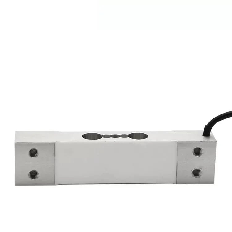
WST201
- Rated loads 3 to 100 kg, aluminium, 4-wire, 350 Ω bridge
- C3, composite error ±0.02 %F.S, output 2.0 ± 0.2 mV/V, IP65
- Recommended excitation 5 to 12 V, digital temperature compensation, compensated minus 10 to plus 40 °C
The workhorse for bench and platform scales under a fixed cover. Its safety overload is 120 % of rated capacity, the lowest here, so it belongs where containers are placed rather than thrown, and not in a wash zone.

WST216
- Rated loads 4 to 30 kg, anodised aluminium, platform up to 200 by 200 mm
- C3, ±0.02 %F.S, output 2.0 ± 0.2 mV/V, IP65
- Operating range minus 35 to plus 70 °C — the widest in this group
Chosen when the cell sits inside a machine enclosure that runs hot, and when the platform is small. Safety overload 150 %, ultimate 200 %. Again IP65, so it needs a cover rather than a rating.

WST217
- Rated loads 5, 10, 20, 50, 100 kg, deck up to 250 by 250 mm
- Linearity ±0.015 %R.O., repeatability ±0.01 %R.O., IP66 with a moisture-proof coating
- Six-wire shielded cable, 3 m, and a 150 % safe / 200 % ultimate overload
The default for a washable deck. Two entries on its own page need confirming before you parallel these cells: the output is published as 2.0 ± 5 %mV/V, and the input resistance as 405±102 with no unit, which I read as 405 ± 10 Ω. Ask for a drawing rather than trusting either.

WST218
- Rated loads 20, 30, 50, 100 lb, stainless steel, platform up to 200 by 200 mm
- C3, output 2.0 ± 0.25 %mV/V, IP67, six-wire 3 m cable
- Output adjustable and an overload stop provided specifically for parallel use
The one to choose when several cells work together under one deck, because the trim is built in and the published sensitivity tolerance is tight enough to matter. Rated loads are in pounds only, so convert before you order.
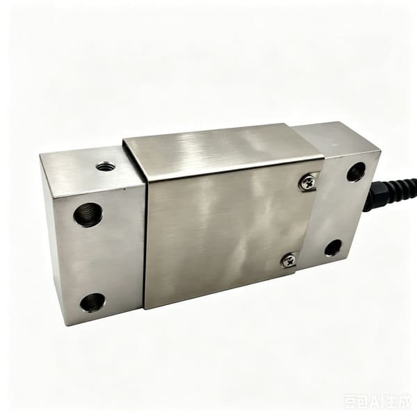
WST219
- Rated loads 50, 100, 200, 250, 500 lb, stainless steel, deck up to 400 by 400 mm
- C3, linearity ±0.02 %R.O., repeatability ±0.015 %R.O., IP66
- Six-wire 3 m cable, safety 150 % / ultimate 200 % rated capacity
The larger deck version, useful on the checkweigher or the sampling scale that verifies the filler rather than on the filler itself. Rated loads are in pounds only here too, so check the conversion against your gross weight.
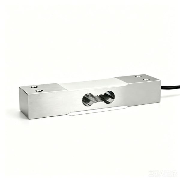
WST1201
- Rated loads 3 to 50 kg, division 0.1 g up to 5 kg and 1 g from 6 kg, composite error 0.005 %F.S
- Zero and output temperature coefficients both 0.002 %F.S per °C, giving 0.02 % per 10 °C
- RS485 or RS232 with Modbus RTU, 1 200 converter samples per second, 300 000 count resolution, IP65
The one to use when the dose is measured in grams and the controller can take a serial number instead of a millivolt. Factory calibrated with eccentricity compensation, so there is no site calibration. IP65 and a four-wire lead, so keep the run short and the water away.

WST1207
- Rated loads 60, 100, 200, 300 kg, stainless steel, fully welded seal, 5-pin bayonet with glass-to-metal feedthrough
- Y factor 10 000 at C3 and 15 000 at C6, so a minimum verification interval of 6 g and 4 g at 60 kg
- CANopen and Modbus RTU, refreshed at 50 Hz, built-in surge protection, IP68 and IP69K, OIML R60 C6 pending
My default for a weighed supply vessel or metering vessel: cable length has no effect on system accuracy, because the signal is already a number, and the sealed stainless body survives a clean-in-place cycle that an aluminium cell does not. The C6 grade and the CPA mark are both still pending, so treat the C3 figures as the ones you can order today.
If none of the seven matches your machine, that is normal and it is not a problem. We make sixteen product families and we do custom versions regularly; the useful thing to send is the fill size, the container, the number of weighing points and the cycle time, and we will tell you honestly whether the machine as designed can hold the tolerance before we tell you which cell to buy. If your application is the small end — liquid dosing in tenths of a gram rather than kilograms — the closest thing I have written is Load Cells for Smart Coffee Machines.
16. What I ask before I quote, and the routine that keeps the number
Nearly every quotation I send for load cells for liquid filling machines starts with the same ten questions. They take a customer ten minutes to answer and they change the recommendation in about half the cases, which is a good enough ratio to keep asking them.
| What I ask for | Why it decides the answer |
|---|---|
| Net fill mass, and the class you intend to declare | Sets the legal allowance in grams, which is the only budget that matters |
| Container tare and how much it varies within a batch | Sets the per-fill allowance directly, and forces the live-tare or preset-tare decision |
| Any carrier, puck or tray that rides through the weighing zone | Adds a machine part to every tare, and a machine part wears |
| How the fill is decided: additive, multi-head, subtractive, or on a carrier | Determines which cell errors survive and which cancel |
| Rated capacity of the weighing vessel or platform | Gives capacity divided by fill, the number that decides everything |
| Number of heads and cycle time | Sets the settling window and the flow rate, which set the drop and its scatter |
| The smallest container the line will ever run | Sets the rated minimum fill, and therefore the finest division you can legally use |
| Temperature range of the product and of the hall | Drives both the density argument and the zero-drift term |
| Washdown or clean-in-place regime | Chooses between coated aluminium, stainless, and a fully welded sealed body |
| Whether the machine prints the actual fill weight | Decides whether you are a filling instrument or a catchweigher, before anything else is discussed |
The routine that keeps the number afterwards is shorter still, and deliberately boring. Certified weight on the platform at the start and end of every shift, deck wiped both times, recorded with the initials of whoever did it. A wipe of the weighing zone at every break, written into the shift sheet. The tare re-measured at every container delivery rather than typed in from last month. Sixty consecutive fills whenever the average is in question, weighed on a control instrument that has itself been verified. And a weekly look at the machine’s own drop-correction log, because a drop value walking in one direction is the earliest warning you will ever get, and reading it costs nothing.
On a line filling a thousand bottles a minute, hour after hour, the recurring cost of overfilling by five grams a bottle is measured in tens of tonnes of product a year, and the majority of it is recovered by fixing tare, drop and settle time rather than by buying a better cell. A load cell is a small part of the purchase price and an even smaller part of the error budget in most installations. Buy the cell that makes the machine repeatable, and spend the rest of the budget on the plumbing, the cleaning interval and the control instrument.
17. Questions I get asked about load cells for liquid filling machines
Which load cell should I use on a liquid filling machine?
Start with one division, not with an accuracy class. Take the rated capacity of the weighing vessel and divide it by the net fill. Below about twelve, an ordinary class C3 cell with 0.02 percent of full scale repeatability is a comfortable fit at class X(1). Between twelve and sixty it depends on the class you are declaring. Above sixty, no cell leaves you enough of the per-fill allowance, and the answer is a smaller weighing vessel rather than a better sensor.
How do I find out whether the load cell or the machine is causing my fill error?
Put a certified test weight on the platform at the start and end of a shift, deck wiped clean both times, and compare the readings. If they agree to within the cell’s own repeatability, the cell is not your problem and you have saved a purchase order. Then look for an accumulating force in the weighing zone: product film on the deck, a drip tray draining into the weighing area, a nozzle or hose resting on the container, or a zero taken only once per shift. Drift through the day is nearly always one of those four.
Why does a filling machine need a two-stage or dribble fill?
Because the drop — product in the air plus whatever the valve delivers while closing — is the flow rate multiplied by the closing time, and at full flow it can exceed the entire legal allowance. On a one kilogram fill at one kilogram per second with a 45 millisecond valve, the drop is 45 grams against a 12 gram allowance. The loop absorbs a drop that is constant, but its scatter, roughly twelve percent of it, it cannot. Throttling to a twentieth of the fast rate cuts the drop to 2.25 grams and its scatter to well under ten percent of the allowance.
Does a filling machine need a legal-for-trade load cell?
It needs a cell whose test data supports the instrument’s declared class, which in practice means an OIML R60 component certificate. An R60 certificate says the cell may be used inside a verified instrument; it does not transfer to your machine and does not make anything compliant on its own. In the United States there is a further fork, because NIST Handbook 44 section 2.24 removes filling machines from that code where the plant runs its own statistical quantity-control programme with traceable standards.
What IP rating does a load cell need on a liquid filling line?
IP65 is enough where the cell sits under a cover and only sees splashes. IP66 or IP67 is the working choice for a machine that gets hosed down. IP68 and IP69K are for a high-pressure hot wash, which on a filler usually means the weighed vessel rather than the deck. Two things the rating does not tell you: whether the seal material survives your cleaning chemistry, because every IP test uses fresh water, and whether the cable entry and junction box are sealed to the same standard.
Do I need a class C6 cell instead of a class C3 cell?
Only where capacity divided by fill forces it. C6 typically halves the zero temperature coefficient and improves repeatability three or four times, but it does not change the ratio, so on a vessel fifty times the fill it still leaves nearly half the legal allowance spent on the cell. Moving the fill onto a smaller intermediate metering vessel usually buys ten times more, for less money. Watch the legal floor too: a better class has a larger rated minimum fill at the same division.
Can I fill five grams by weight on a normal filling machine?
At the small end the rated minimum fill runs at about eleven divisions for class X(1), so a five gram pack needs a division of 0.45 grams or finer. Then add the rest: the control instrument has to be three times better than the tolerance, about 24 milligrams, and the residual drop during valve closure can exceed the whole allowance at production flow rates. The architecture that works at this dose is a multihead weigher, where many small hoppers are weighed at once and combined.
Can you supply the complete filling machine, or just the weighing parts?
The weighing layer only, and I would rather be exact about where the line is. I supply load cells and force sensors, matched sets with the matching data in writing, summing junction boxes, weighing indicators and transmitters, plus the arithmetic and mounting advice that goes with them. I do not supply the nozzle, valve, pump, indexer, conveyor or the filling controller’s drop-learning software, I cannot approve or verify your filler, and I supply nothing that performs a safety-rated function.
Net fill and the class you intend to declare, container tare and how much it varies, any carrier or puck, the number of heads, the cycle time, and the washdown regime. I will come back with capacity divided by fill, the cell’s share of your legal allowance in grams, a capacity with the utilisation, whether an intermediate metering vessel is cheaper than a better cell, and a written note on which parts of your error are not mine. If a better load cell is not your limiting factor, that will be the first line of my reply.
VektorForce · load cells, force sensors, junction boxes and weighing indicators · www.vektorforce.com · Robin@vektorforce.com