
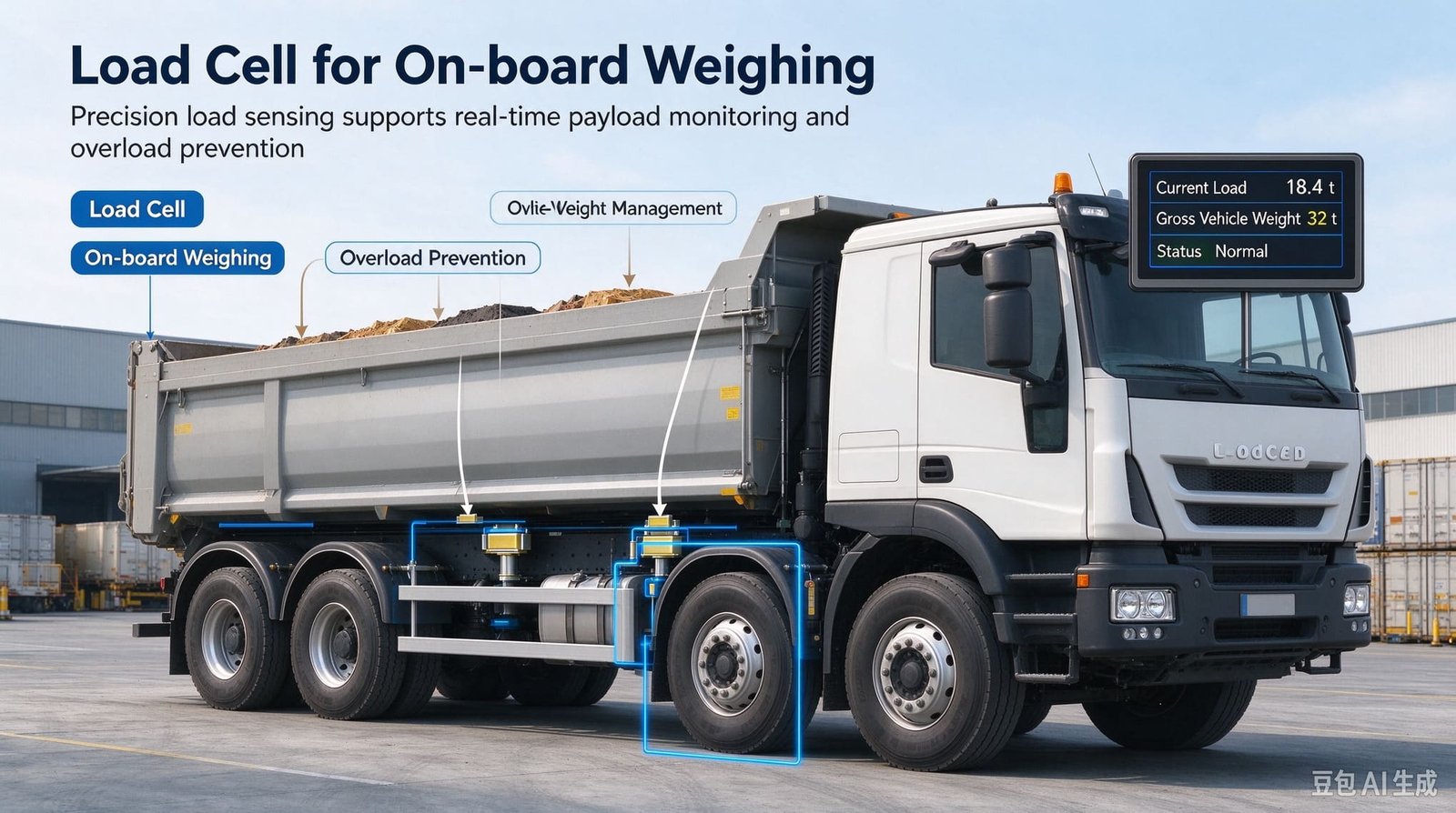
A truck weighs its payload through a suspension and chassis that are looser than any load cell.
An on-board weighing system is not a weighing instrument that happens to be fitted to a truck. It is a truck that happens to be a weighing instrument, and the truck is the weaker half. Nine out of ten inquiries about a load cell for on-board weighing arrive with the sensor’s accuracy already written down and the payload’s real error budget not written down at all. This is what I send back instead of a price.
27 October 2026
10 min read
OIML R60 · R51 · R134 · MID MI-006 · 96/53/EC
- Why the first number a customer sends me is the wrong one
- Three ceilings on a truck, and only one of them is a sensor
- What I supply, and what I do not
- Two families of on-board weighing, and four places a sensor can sit
- Project 1 — A refuse truck OEM and the 30 kg bin that vanished
- Project 2 — A tanker fleet where the suspension chose the sensor
- Project 3 — A wheel loader OEM, and why 0.02 % was the right buy
- Which rule book actually owns your truck
- Four vendors, four different definitions of “accuracy”
- Error budget and the zero-drift budget nobody writes down
- Mounting, calibration, and what a certificate really costs
- Seven mistakes I keep seeing, and the 7-step path I use now
- Who owns what: a standards map for vehicle weighing
- Where the weighing core ends
- Load cells for on-board weighing: the six parts I actually quote
- Frequently asked questions
1. Why the first number a customer sends me is the wrong one
An inquiry arrived in July from a bodybuilder in Southeast Asia. One paragraph, one drawing, one number: “We need on-board weighing for a 20 ton refuse truck. Please quote load cells with 0.02 % accuracy.”
The number was not wrong because it was too ambitious. It was wrong because of what it was a percentage of. That truck has a gross vehicle weight of 20 000 kg and a kerb weight of about 12 000 kg, so the permitted payload is 8 000 kg. Every kilogram of error is produced on the whole 20 tonnes, because that is what the sensors carry, and judged against the 8 tonnes of cargo, because that is what the customer sells.
| Vehicle type | GVW (kg) | Tare (kg) | Payload (kg) | Tare share | Amplification | 0.1 % FS on GVW, seen on the payload |
|---|---|---|---|---|---|---|
| Closed-body refuse truck | 20 000 | 12 000 | 8 000 | 60.0 % | 2.500× | 20 kg, which is 0.250 % |
| Bulk tanker, food or chemical | 22 000 | 16 000 | 6 000 | 72.7 % | 3.667× | 22 kg, which is 0.367 % |
| 5-axle articulated, at the EU limit | 40 000 | 15 000 | 25 000 | 37.5 % | 1.600× | 40 kg, which is 0.160 % |
| Empty tipper running to a tip | 26 000 | 13 000 | 13 000 | 50.0 % | 2.000× | 26 kg, which is 0.200 % |
Read the last two columns together. A specification written as “0.1 % of full scale” becomes 0.16 % to 0.37 % of the number the customer cares about, purely because of where the tare sits. Nothing about the sensor changed between those rows. Only the vehicle did.
The second half of the trap is that most on-board systems are not one sensor. A four-point superstructure system on that truck is usually four cells, and their errors do not cancel — they accumulate in the sum. With 5 t cells on a 20 t system, the error in the summed reading works out at 4 kg per cell at 0.02 % FS, 10 kg at 0.05 %, 20 kg at 0.1 %, 60 kg at 0.3 % and 100 kg at 0.5 %. In other words the ordinary 0.1 % cell already contributes 20 kg on an 8 tonne payload, which is 0.250 % — and every one of those four parts looks excellent on its own datasheet.
Look at the middle row again. Even an ordinary 0.1 % cell produces 20 kg on an 8 tonne payload — and a bin lorry lifting one 30 kg wheelie bin is being asked to resolve one and a half times the noise floor of its own sensor chain, before a single tyre has rolled. I come back to that in section 5, because it is the most common misunderstanding in this application.
Percent of full scale is a statement about a range, not about a vehicle. Two cells with identical 0.1 % FS figures behave completely differently on a truck whose tare is 37 % of GVW and one whose tare is 73 %. Before I quote load cells for on-board weighing I ask four questions: GVW, tare, the payload the customer actually sells, and the axle limits on the routes the vehicle runs. Without those, an accuracy figure is a decoration.
2. Three ceilings on a truck, and only one of them is a sensor
Every load cell for on-board weighing sits under three independent accuracy ceilings. They are set by three different parties, improved by three different budgets, and only the first is something I sell.
| Ceiling | Who sets it | Typical magnitude | How you improve it |
|---|---|---|---|
| The load cell | The sensor manufacturer | 0.02 % to 0.5 % FS | Money, and it arrives next week |
| The suspension | The vehicle, as built | 1 % to 10 % of the load at that point | A new truck, or an air conversion |
| The law | The regulator | 1 % to 16 % in service, depending on class | You do not. It is given to you |
The second row is where on-board weighing projects are won and lost, and it is the one row no sensor supplier controls. Suppliers of on-board load-sensing systems publish suspension repeatability anywhere from 1 % to 7 % of the load at the axle and 3 % to 10 % of GVW for the whole-vehicle reading. Section 9 sets those sources side by side, because they do not agree with each other and the disagreement is instructive. Using a European driven-axle limit of 11 500 kg as the reference:
| Source of error | Figure | On a 11 500 kg driven axle | Ratio to the best sensor |
|---|---|---|---|
| Load cell, best case | 0.02 % FS on 15 t | 3.00 kg | 1.0× |
| Load cell, common case | 0.05 % FS on 15 t | 7.50 kg | 2.5× |
| Load cell, workhorse | 0.1 % FS on 15 t | 15.0 kg | 5.0× |
| Air suspension repeatability | 2 % of axle load | 230 kg | 76.7× |
| Leaf spring repeatability | 5 % of axle load | 575 kg | 191.7× |
| Leaf spring, worst published | 7 % of axle load | 805 kg | 268.3× |
At whole-vehicle level the arithmetic is blunter still. At a 40 000 kg GVW a 3 % suspension figure is 1 200 kg, a 5 % figure is 2 000 kg and a 10 % figure is 4 000 kg. Against a 0.02 % sensor on a 40 t system — 8 kg — a 2 000 kg suspension error is 250×. Even the best published whole-system figure in section 9, 0.5 % to 1.0 % of maximum, gives 400 kg at 40 t: still 5× the sensor chain above it. Upgrading a cell from 0.1 % to 0.02 % on a steel-spring vehicle moves the system reading by essentially nothing.
If the vehicle’s own suspension repeats to 575 kg and the display resolves to 5 kg, the extra resolution is not information. It is a decimal place. When a customer asks for 0.02 % on a steel-spring tipper I quote it — and in the same email I quote the number the truck will actually deliver, and what the difference would buy if it went on a reference vehicle and a proper in-situ calibration instead.
3. What I supply, and what I do not
I am a weighing-component exporter. I make the sensing layer, the summing layer and the indicating layer, and I help design how they go together on your machine. I do not make the machine and I do not take responsibility for it. That table goes into every quotation for load cells for on-board weighing, because it is the fastest way to find out whether we are relevant to each other.
| I supply | I do not supply |
|---|---|
| Load cells: double-ended shear beam, single-point, pin and shaft type, micro-strain type | The finished on-board weighing product under a customer’s own brand |
| Junction boxes and summing boxes, including multi-channel with per-channel output | Vehicle-side integration: the CAN protocol implementation in your ECU, the harness, the OEM software |
| Weighing indicators, including indicators with serial or CAN output | Type approval, conformity assessment or a risk assessment for your vehicle |
| Matching test data and calibration records for the parts I ship | Safety-rated devices, performance-level claims, or a signed statement that an installation is safe |
| Sensor selection, load-path arithmetic and mounting advice on our own parts | Air-bag pressure sensing or hydraulic pressure sensing — buy those from the suspension and hydraulics people |
| Custom mechanical variants: envelope, thread, cable length, connector, output | The telematics platform, the fleet dashboard, the billing integration |
| Cabling, wiring convention and shielding practice for the weighing side | Legal-for-trade approval of the system as installed on your vehicle |
I can design the weighing solution. I cannot design your vehicle. Once a number has to survive a type-approval file, a roadside scale or an insurance claim, the party that signs it has to be the party that built the machine. What I can do is make sure the sensing layer under that signature is still telling the truth in year three, and give you the drift and overload data to prove it.
4. Two families of on-board weighing, and four places a sensor can sit
“On-board weighing” is used in the trade for two structurally different things, and the choice between them is made by the vehicle rather than by the customer. Both are installed on the vehicle and both report weight. They fail in completely different ways.
Family A — axle or frame strain (on-axle). Sensors measure the deformation of the axle or frame while the vehicle carries its load. Installation is simple, the structure is untouched, and the original safety margins survive. The limitation is equally simple: it needs a body with genuine stiffness, and most vehicles do not have one, because a chassis rail is designed to flex. The signal is also disturbed by braking, cornering, potholes and differential torque, so accuracy ends up lower and drifts with conditions rather than load. I use this family where a 3 % to 5 % payload reading is genuinely enough: overload warning, not billing.
Family B — superstructure support (on-chassis). The body is rigid by construction — a tank barrel, a closed refuse body, a tipping cradle, a mixer drum frame — so sensors go where the body rests on the chassis. Four cells under a rigid body imply two assumptions the customer must honour: the body is a rigid body, and it rests on four points that share load. When those hold, accuracy beats Family A. When they do not, you get the failure I describe in section 11: one corner high, one low, and a total that is right by accident.
Both families share one non-negotiable prerequisite, and it is why so many of these projects stall in the first email: before a design can be drawn, the mounting positions and the relevant structural drawings have to exist. I cannot pick a capacity, an envelope or a load path from a photograph of a whole truck. I need the section where the sensor will sit.
Inside Family B there are four conventional positions, plus a fifth that is a different idea altogether:
| Position | What the sensor carries | Typical vehicle | The trap |
|---|---|---|---|
| Trunnion | The pivot load of a tipping body, shared between two trunnions | Tipper, skip loader, hooklift | Load shifts rearward as the body tips; a trunnion sensor reads a changing fraction, not the payload |
| Tipping ram | Hydraulic pressure, or the ram reaction through a pin | Tipper, refuse compactor body | Only meaningful while lifting. An event sensor, not a weighing device |
| Cradle bracket | The vertical reaction of a tank or container shell on its saddle | Tanker, demountable container, roll-off | Saddle stiffness mismatch; a soft saddle sheds load onto its neighbour and the sum still looks plausible |
| Hinge bar bracket | The rear hinge reaction of a tipping body | Tipper, walking floor, ejector trailer | Cannot be loaded with the body tipped; the bracket has to be designed for the sensor, not adapted afterwards |
| Pin replacement | Whatever the original pin carried — 100 % of it, or exactly half | Any vehicle with an accessible pivot in the load path | The pin must be prevented from rotating; it needs an anti-rotation feature designed in, not added later |
A load cell does not measure the load. It measures the force at the point where you installed it. On a truck this is not philosophical. Move the mounting position from the trunnion to the cradle bracket on the same vehicle and the sensor sees a different force, at a different angle, with a different dynamic content — and the payload number changes shape with it. The first thing I ask for is never a capacity. It is a drawing with the candidate mounting points circled, and a photograph of the underside.
If you want the sensing physics underneath all of this before the application detail, that is a separate article and I will not repeat it here: start with the complete guide to load cell working principles and types. If the vehicle is a scissor lift or a work platform rather than a truck, the weighing question changes shape entirely — that one is covered in field notes from 200+ lifting platform projects. And if what you have is a stationary vessel on legs rather than a vehicle, the tank version of this problem is in load cells for tank weighing systems.
5. Project 1 — A refuse truck OEM and the 30 kg bin that vanished
In July a bodybuilder in Southeast Asia asked me for load cells for on-board weighing on a closed-body refuse truck. Their specification had two requirements, and the second was the interesting one: total payload on the display, and the weight of each individual bin as it was tipped. They wanted both from one set of load cells, and they had already written down 0.02 % for the cells.
I sent back the tare arithmetic from section 1 — 20 t GVW, 12 t tare, 8 t payload, a 2.5× amplification — and then the bin arithmetic, which is what actually settled the design.
| What the system has to resolve | Mass | Against a 5 % error at 20 t | Against a 1 % error at 20 t |
|---|---|---|---|
| One 240 litre wheelie bin | 30 kg | noise is 1 000 kg — ratio 1 : 33.3 | noise is 200 kg — ratio 1 : 6.7 |
| A full collection round | 300 bins, 9 000 kg | noise is 11.1 % of the round | noise is 2.2 % of the round |
| One bin against the sensor chain’s own error | 30 kg | the cell chain alone contributes 20 kg at 0.1 % FS | 1.5 kg of signal for every 1 kg of sensor uncertainty |
That third row is the one I asked them to read twice. A four-cell chain at 0.1 % FS produces about 20 kg of uncertainty in the summed reading, and a 30 kg bin is one and a half times that. Asking the load cell chain to weigh a single bin is asking a bathroom scale to weigh a letter. So I refused half the specification and explained why: the bin mass is not a load-cell problem. It is a differential, event-based measurement — you do not need the absolute mass on the body to know that the body got 30 kg heavier between the bin leaving the ground and coming back down. The reference is the state of the truck two seconds earlier, not zero. Mixing the two into one sensor chain makes both readings worse.
Here is what I actually quoted. Four double-ended shear beam cells under the body cradle, one per support point, and I specified our WST1406 — for reasons that were all about the vehicle rather than the accuracy number:
| Why WST1406 for a refuse body | Published figure |
|---|---|
| A bin lorry lives in a washdown regime and sees leachate | Fully welded, sealed, IP68 |
| The body is dropped and slammed thousands of times | Safe overload 200 % FS, ultimate 300 % FS |
| Cyclic loading, every working day, for the life of the vehicle | Fatigue life > 1 000 000 cycles at Emax; deflection < 0.5 mm |
| The vehicle’s own temperature envelope, not the workshop’s | Operating −40 to +65 °C; compensated −10 to +40 °C |
| It has to be a drop-in on existing vehicle electronics | 350 ± 3 Ω output, 384 ± 10 Ω input, 1.125 ± 0.005 mV/V |
| Accuracy has to be a floor, not a selling point | 0.1 %, repeatability < ±0.02 % AL, creep 30 min < ±0.020 % AL |
A four-channel junction box instead of a summing box. This is the part customers almost always try to cut, and on a vehicle it is the part that saves the project. A summing box adds four bridge outputs into one number, so a chafed cable, a waterlogged connector or one mechanically damaged cell simply drops the sum — and the display shows a smaller, entirely plausible number. A four-channel box keeps the channels separate so the indicator can compare them, and a channel that has failed or drifted away from its neighbours can be flagged instead of averaged in.
How bad is the silent case? Losing one of four channels leaves the system reading 75 % of the real mass: at a true 8 000 kg payload the display shows 6 000 kg, a silent error of 10 % of gross vehicle weight. That one failure is 25 times the operator’s own 1 % payload tolerance, 100 times the whole four-cell sensor contribution, and 3.5 times the 5 % threshold that gets a truck pulled over in Germany. One chafed cable, no warning on a summing box.
A separate channel for the bin lift. The bin mass came off the lift mechanism — hydraulic pressure on the lift cylinder during the cycle, with the body-weight signal as the reference — and the two readings were never mixed. The payload total stayed on the load cells where it belongs, with a much longer averaging window than any per-bin reading could tolerate.
They asked me to confirm, in the quotation, that the system would weigh each bin to better than ±1 kg. I said no, in writing: no four-cell on-board system on a 20 tonne vehicle can make that claim, because the sensor chain’s own uncertainty at that instant is twenty kilograms and the bin is thirty. A supplier who signs that sentence is either not measuring what they think they are measuring, or is about to hand over a system that fails its first acceptance test. I would rather lose the line item than own that argument for three years.
One more thing went into that quotation, because it is a mechanical fact customers forget once the electronics work: a four-point body is statically indeterminate. It has one more restraint than a three-point body, so the load share at each corner depends on the stiffness of the four supports, not just on where the mass is. The effect is not small:
| Stiffness ratio between opposite supports | Share taken by the stiffer side | Error if the electronics assume an equal split |
|---|---|---|
| 1 : 1 | 50.0 % | 0 % |
| 1.1 : 1 | 52.4 % | 4.8 % relative |
| 1.2 : 1 | 54.5 % | 9.1 % relative |
| 1.5 : 1 | 60.0 % | 20.0 % relative |
| 2 : 1 | 66.7 % | 33.3 % relative |
This is why I ask about body structure and not only about cells. If one cradle bracket is bolted to a crossmember and its diagonal partner sits on a shimmed pack, the four readings will never be equal, and the total will be right only because four wrong-looking numbers happen to add up. Here we specified the brackets as a matched set with a defined flatness, and the body was shimmed before the cells were installed — not after the readings looked strange.
The lesson I keep re-learning: when a customer asks for two different measurements from one sensor chain, the answer is almost never better sensors. It is to separate the measurements. The payload total and the bin weight are not the same problem at two resolutions; they are two problems that happen to occur on the same vehicle. Splitting them cost nothing and removed a claim I could not have kept.
6. Project 2 — A tanker fleet where the suspension chose the sensor
The second project was a retrofit rather than an OEM build, and that changes the brief. A liquid transport operator in Eastern Europe runs three tractor units and five trailers built between 2011 and 2019, mixed air and steel suspension, and wanted payload indication on every combination. Their first email asked for “one sensor that fits all of them”. There is no such sensor, and explaining why was most of the project.
Start with the tare question on a tanker, because it is the worst case in this application. A 22 000 kg GVW food or chemical tank typically carries 16 000 kg of vehicle and 6 000 kg of product — a tare share of 72.7 % and an amplification of 3.667×. Every kilogram of weighing error is generated on 22 tonnes and judged against 6.
Now the suspension split, which is the real engineering decision. Air-suspended axles can be weighed by measuring air-bag pressure — non-invasive, no modification, cheap, and already served by several established suppliers. Steel-suspended axles cannot: a leaf spring presents no pressure to measure, so the signal has to come from strain, taken where the structure actually deforms under load.
That distinction decided the part list, and it splits three ways. An air-suspended axle is best served by an air-bag pressure sensor, which is not our product — I told them plainly to buy it from the suspension specialists rather than push an inferior route out of ego. A steel leaf spring has no pressure to read, so the signal has to be deformation: a micro-strain sensor, and that is where our WST703 belongs. And a rigid body on supports is the one case where a direct-force part is best, which is why WST1406 sits under the cradle on this kind of trailer. Any claim that a bolted-on gauge repeats as well as a purpose-built load cell would be one I cannot support.
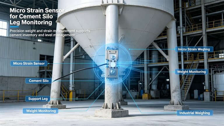
WST703 covers 300 to 1 000 με in alloy or stainless steel with an IP65 body, and measures structural deformation directly — exactly the quantity an axle- or frame-based system needs. Two honest caveats came with it. Our own product page files it under silo weighing and structural monitoring rather than under vehicles, which is a marketing gap rather than a technical one, since the device does not care whether the strain is in a silo leg or a chassis rail. And that page’s address is /product/micro-strain-sensor/, with no model number in it, so typing “WST703” into a search box will not find our page. I would rather say that than have a customer conclude we do not make the part.
Once the fleet contained two different sensor technologies, the temperature question became unavoidable, and it is where retrofit projects quietly go wrong. A European tanker sees roughly −40 to +65 °C ambient over a year, a span of 105 °C. What matters is not how wide the sensor’s operating range is, but whether the compensated range covers the temperature in which the truck actually gets loaded:
| Part | Compensated range | Span | Coverage of a 105 °C year | Operating range |
|---|---|---|---|---|
| WST1406 | −10 to +40 °C | 50 °C | 47.6 % | −40 to +65 °C, full cover |
| WST1401 | not published | — | — | −20 to +65 °C, 81.0 % |
| WST1402 | not published | — | — | −20 to +65 °C, 81.0 % |
| WST708 | −35 to +70 °C, full cover | 105 °C | 100 % | −10 to +40 °C, only 47.6 % |
| WST211 | −10 to +60 °C | 70 °C | 66.7 % | −20 to +80 °C |
Read the WST708 row carefully, because it is inverted relative to expectation: its compensated window is the widest in the group, 105 °C, but its operating window is only 50 °C, from −10 to +40. Outside that the part is outside its stated operating condition, whatever the compensation network is doing.
The second number I make customers calculate is the zero drift budget. OIML R134-1:2006 states that a change in ambient temperature of 5 °C must not move the zero or near-zero indication by more than one scale interval. On a system with a 50 kg interval that is a permitted drift of 10 kg per °C, and it is the budget the whole chain has to fit inside, not the budget for one cell.
| Part and range | Zero temperature effect | Per cell | Four cells | Share of the 10 kg/°C budget |
|---|---|---|---|---|
| WST1406 at 15 t | < ±0.002 % Emax per °C | 0.300 kg/°C | 1.200 kg/°C | 12.0 % |
| WST708 at 7.5 t | ±0.07 % FS per 10 °C | 0.525 kg/°C | 2.100 kg/°C | 21.0 % |
| WST1402 at 15 t | ±0.05 % FS per 10 °C | 0.750 kg/°C | 3.000 kg/°C | 30.0 % |
| WST211 at 2 t | ±0.017 % FS per 10 °C | 0.034 kg/°C | 0.136 kg/°C | 1.4 % |
Two things fall out of that table. All four options sit comfortably inside the legal budget, so zero coefficient is not the problem customers fear. And what matters is the swing a vehicle really sees in a day: WST1406 at 1.200 kg/°C across four cells, over a 20 °C shift between a cold morning loading and a warm afternoon weighing, is 24 kg — on a 6 000 kg product load, 0.30 %. Real, but an order of magnitude below the suspension, and it disappears if the system re-zeros with the vehicle empty and stationary, as it should.
Two gaps in our own documentation would have hit this customer within a week: the WST1401 and WST1402 pages publish neither an ingress protection rating nor an ultimate overload figure. For a retrofit under a trailer that is not a small omission — IP decides whether the part survives five winters of salt spray, and ultimate overload tells you how much abuse it forgives. I quote both from our test records rather than pointing at the page.
On this tanker fleet the tare is 72.7 % of gross. A tare error of one part in a thousand — 16 kg — lands entirely on a 6 000 kg load as 0.27 %. It does not wash out over a shift, it does not average with the previous load, and re-weighing the same vehicle twice does not halve it, because the same error is present both times. It is a fixed offset on the only number being sold. This is the one term a load cell alone cannot fix and a good calibration procedure can, which is why section 11 spends most of its length on calibration rather than on parts.
7. Project 3 — A wheel loader OEM, and why 0.02 % was the right buy
I have spent two sections telling customers that better cells buy them nothing. Then a construction equipment maker asked me for a wheel loader payload scale and I quoted the most accurate part in our range. Here is where the line actually sits.
The two parts in question are WST1401 and WST1402. On paper they are the same family: double-ended shear beam, 2.0 mV/V sensitivity, same 750 ± 15 Ω input, same 700 ± 5 Ω output, same 150 % FS safe load, same 10 V DC bridge reference. The difference is one number in the accuracy column.
| Specification | WST1401 | WST1402 |
|---|---|---|
| Rated load | 10 to 300 kN (about 1 to 30 t) | 15 to 100 kN |
| Combined error | 0.02 to 0.05 % FS | 0.3 to 0.5 % FS |
| Bridge resistances | 750 ± 15 Ω in, 700 ± 5 Ω out | 750 ± 15 Ω in, 700 ± 5 Ω out |
| Zero and output temperature effect | ±0.02 % FS per 10 °C both | ±0.05 % FS per 10 °C both |
| Creep, 30 min | ±0.02 % FS | ±0.05 % FS |
| Safe load | 150 % FS | 150 % FS |
| Ingress protection | not published | not published |
| Ultimate overload | not published | not published |
Two identical mechanical designs, one order of magnitude apart on error, and a price difference to match. On a steel-spring refuse truck I would have sent the 1402 and explained that the difference disappears into the suspension. On a wheel loader payload scale I sent the 1401 — and I want to be precise about why, because “it is more accurate” is not the reason.
A loader payload scale is not selling a mass. It is selling a repeatable count. The operator lifts the same bucket of aggregate onto the same truck, over and over, all day, and the only question the system has to answer reliably is whether the load has reached the target. Nobody bills by the loader reading. What this application needs is repeatability and stability under a cycle, which is a different specification from the absolute accuracy of any single reading — bucket geometry, lift-arm linkage and force direction do most of the damage to absoluteness, and no cell repairs that.
What the low-error element buys is narrower and more useful: with 0.02 % FS error, ±0.02 % FS per 10 °C temperature effects and 0.02 % FS creep, the same machine on the same day returns the same number for the same lift, and four matched bridges keep current sharing tight in parallel. That is what a target-based payload scale eats for breakfast, and it is worth the price. I said so in writing, and I said I would have recommended the opposite had this customer asked me to weigh a road tipper.
Then the lifecycle arithmetic, where a loader is nothing like a truck. Our double-ended shear beam range is fatigue rated at more than 1 000 000 cycles at Emax. A front loader in a quarry cycles its bucket continuously rather than rolling down a road, so let us spend that allowance honestly:
| Bucket cycles per day | Cycles per year at 300 working days | Calendar life of the 1 000 000 cycle allowance |
|---|---|---|
| 100 | 30 000 | 33.3 years |
| 200 | 60 000 | 16.7 years |
| 400 | 120 000 | 8.3 years |
Those figures only hold if the sensor actually cycles through Emax, and a payload scale spends most of its life below the bucket rating, so the real allowance is larger. What will end the part’s life first is not fatigue: it is impact. Dropping a loaded bucket into the stop, or digging into a face, produces shock loads that never appear in a nominal duty cycle, which is why the 150 % FS safe load matters more here than the 0.02 % does. I told that customer the same thing — repeatability is why I chose the accurate part, overload margin is why it will survive, and those are two different lines in the table.
One last thing I insisted on, because a loader’s turning circle is short and its wiring environment is brutal: a four-channel junction box with per-channel monitoring, not a summing box. The reasoning is the same as on the refuse truck, and here it is worth even more, because a loader that loses a wheel-load channel does not stop working. It keeps lifting, all day, showing a number that is 75 % of the truth.
A digital cell or a monitored multi-channel system has a worse immediate failure mode: it goes dark, or raises a fault, and the machine stops being trusted. On a vehicle payload scale that is not a downgrade, it is the point. A scale that fails loudly costs you a shift; a scale that fails quietly costs you the fine, and then the next one, because nobody knew the number was wrong. When a customer asks me to save 40 dollars by dropping the four-channel box, that is the trade I describe, and the trade I will not make quietly for them.
8. Which rule book actually owns your truck
Four international recommendations look like they might govern load cells for on-board weighing. One of them explicitly refuses to, and finding that out changed the advice I give. OIML R76 covers non-automatic instruments, including those mounted on a vehicle. OIML R51 covers automatic catchweighers and expressly includes instruments mounted on a vehicle that weigh automatically while it is stationary, which makes R51 the closest match that exists. OIML R106 covers trains. And OIML R134, the road-vehicle weigh-in-motion recommendation, states in its own scope that it does not apply to instruments that “are installed on-board vehicles to measure axle load”.
That sentence is what I now send to customers who say they need “an R134 system”. R134 was written for a fixed site — a weighing zone with controlled speed and approach — precisely because that is the only place where a road-surface-based dynamic measurement can be characterised. Bolt the sensor to the vehicle and you have changed the measurement, and the recommendation says so in its scope clause.
R134 defines two optional nameplate limitations. An instrument not intended to weigh vehicles carrying liquids or other products whose centre of gravity may shift with vehicle movement must be marked “not to be used to weigh vehicles carrying liquids or other products that may be subjected to fluctuations in their center of gravity by vehicle movement”. One not intended for conventional steel leaf spring suspension must be marked “not to be used to weigh vehicles with conventional steel leaf spring suspension”. A tanker is a liquid load. A tipper is a leaf spring vehicle. The two exclusions the drafters felt obliged to name are the two commonest on-board targets in the world — excluded because the load path is not repeatable, the same conclusion sections 2 and 9 reach by measurement rather than regulation.
Now the part that makes on-board weighing commercially interesting, and it has nothing to do with the sensor. The EU mass and dimension directive 96/53/EC sets the numbers every European bulk operator runs against:
| Limit | Value | What it means in practice |
|---|---|---|
| Gross vehicle weight, 5-axle articulated | 40 000 kg | The number a driver is paid to reach and fined for exceeding |
| Gross vehicle weight, intermodal / 6-axle | 44 000 kg | 10 % more, and only on qualifying combinations |
| Driven axle | 11 500 kg | The axle that fails first, and where the suspension error lives |
| Single non-driven axle | 10 000 kg | 15 % below the driven figure, so the same load raises them unequally |
| Steering axle | 7 500 kg | The easiest limit to break by loading too far forward |
| Fifth wheel coupling / kingpin | 12 000 kg | A single-point limit that a load-position change moves fast |
| Two-axle group, spacing 1.8 m or more | 19 000 kg | At less than 1.3 m spacing the allowance rises to 21 000 kg |
| Three-axle group | 24 000 kg | 2.09× the driven axle limit, so an axle group is not simply three axles |
| Width, height, articulated length | 2.55 m, 4.00 m, 16.50 m | Nothing to do with weighing, and everything to do with why the payload is what it is |
Here is the number that makes the whole product category make sense. Because a heavy vehicle is a beam on two supports, moving a load by one metre along the deck can transfer more than a thousand kilograms from one axle group to another. The gross vehicle weight has not changed at all; what changed is which axle is now illegal. A driver who loads to the same total every day can be compliant on Monday and 1 500 kg over on the drive axle on Tuesday, and a system that only reports the total will never tell them.
And the penalties are levied per axle, not per vehicle. That is the most important commercial fact in this article. A three-axle combination found over the limit on each of three axles is three offences in jurisdictions that assess axle by axle — three separate penalties, three administrative lines, and in some countries three separate towing decisions.
| Jurisdiction | Penalty shape | Practical consequence |
|---|---|---|
| Germany | Graded fines from roughly €100 into the thousands; a 5 % overload can mean the vehicle is stopped on the spot | Driver, haulier and loader can all be held responsible |
| France | Assessed per tonne over the limit | The bill scales linearly with how badly the reading was wrong |
| Netherlands | Separate rates for axle overload and for gross vehicle overload | One tonne over on three axles is roughly €1 080, before the GVW element |
| Poland | Fixed administrative penalty around PLN 15 000 | A single event can exceed the margin on an entire load |
| United Kingdom | Fixed penalty for minor cases, unlimited before a court for serious ones | The tail risk is the operator’s licence, not the fine |
| United States | Federal penalties per occurrence, commonly above $5 000 | Per event, per vehicle, and repeatable within the same week |
Enforcement has also been modernising. Since 2023 an increasing number of jurisdictions have moved type-approved weigh-in-motion systems from screening to direct enforcement, issuing fines from a roadside reading rather than using it to select vehicles for a static check, and the EU has pushed member states towards automatic detection on the core TEN-T network. Once a WIM reading is the evidence, the tolerance the roadside instrument is verified to becomes the tolerance your on-board number competes with. And that tolerance is much wider than people assume:
| Comparison | Value | Comment |
|---|---|---|
| Best class, table value at 40 t, initial verification | 40 kg | Nominal 0.10 % — impressive on a certificate |
| Same class, after the floor rule (d = 50 kg, 5 axles) | 250 kg — 0.625 % of GVW | The floor is six times the table value and it governs |
| Loosest class, table value at 40 t, in service | 4 000 kg | 10 % of the vehicle’s total mass |
| Loosest class in service versus best class after the floor | 4.0× | Same road, same truck, four times the tolerance |
| A single-axle or axle-group class in service, worst case | ±16 % of that axle group’s load | At 11 500 kg that is 1 840 kg of permitted error |
| The same class at initial verification | ±8 % — 920 kg at 11 500 kg | Still 1.6× the 5 % that stops a truck in Germany |
| An operator’s own 1 % payload target on 8 t | 80 kg | Good enough for almost every commercial purpose |
| Worst-case axle-group tolerance vs that 1 % target | 23× in service, 11.5× at initial verification | The legal allowance is an order of magnitude looser than the operator needs |
A roadside or axle-group instrument in its loosest approved class may be permitted 16 % of an axle group’s load — 1 840 kg on a laden drive axle. The overload threshold that gets a vehicle stopped and unloaded in Germany is 5 % of that same axle, 575 kg. The permitted error is 3.2 times the threshold that triggers the consequence, and the initial-verification figure is still 1.6 times it. This is not a loophole argument. It is the case for an on-board system with a known, published, repeatable error of 1 % to 2 %, because a tight honest number beats a wide legal one when the argument is whether you were 500 kg over.
9. Four vendors, four different definitions of “accuracy”
Go looking for the repeatability of a suspension under load and you will find several suppliers of on-board load-sensing systems publishing several different numbers that do not reconcile. Not because anyone is lying, but because they are quoting different denominators — and the denominator is doing more work than the product.
| Source | Published figure | Percent of what? |
|---|---|---|
| Supplier A | Leaf spring 5–7 %; air spring 2–3 % on the axle; 5–10 % and 3–5 % respectively on the GVW | Two different bases in one sentence, clearly stated |
| Supplier B | Air spring 1–5 %, leaf 5–10 % on the axle; 3–5 % and about 10 % on the load | Axle load for one figure, load for the other |
| Supplier C | “99 % or better” on air suspension, “97 % or better” on mechanical, referred to a certified axle scale | Closeness to an external reference — so 1 % and 3 % respectively |
| Supplier D | System accuracy 0.5 % of maximum; the weighing component typically 1 % repeatability; overall 0.5–1.0 % of maximum on air | Three layers, separated — the only supplier that does this |
| Supplier E | Air spring 2–3 %, leaf spring 3–5 % | Unstated, which is the actual problem |
Look at what that table really contains. “99 % or better” is 1 % error. “0.5 to 1.0 % of maximum” is 0.5 % to 1.0 % error. “2 % of axle load” on an 11 500 kg axle is 230 kg, which as a fraction of a 40 t gross weight is 0.575 %. Three completely different-looking numbers, possibly describing the same three products. The figure you are handed is chosen by the vendor’s marketing, and you cannot compare two without converting both to a common basis.
The exception is Supplier D, and it is the one I quote, because it is the only one that separates the sensor chain from the system: a system figure of 0.5 % of maximum, a weighing component — in its example the air suspension itself — that typically repeats to about 1 %, and an overall figure of 0.5 % to 1.0 % of maximum on an air-suspended vehicle. That layering is exactly the structure from section 2: the electronics are the small term, the mechanical interface is the large one, and the published overall figure is dominated by it. The same supplier publishes the conditions too, and those are the real specification: the air suspension must be in good condition and not leaking, the vehicle must stand on reasonably level ground, the brakes must be released, and the reservoir must be at normal working pressure.
If a supplier cannot tell you which quantity their percentage is a percentage of, and under what conditions the figure was established, the number is not a specification. It is a mood. Those four installation conditions are worth more than any accuracy claim: a truck on a slope, with the brakes set and an air bag sagging, will be wrong by more than the gap between the best and worst product in this market.
Now put the suspension figures next to a load cell on the same vehicle, on a common basis, using all four cells rather than one. On the refuse truck from section 5, four 0.02 % FS cells on a 15 t range contribute about 12 kg. A 2 % air suspension error on an 11 500 kg axle is 230 kg; a 5 % leaf spring error is 575 kg; a 7 % figure is 805 kg.
| Error term | Magnitude | Ratio to four 0.02 % cells |
|---|---|---|
| Four 0.02 % FS cells at 15 t | 12 kg | 1.0× |
| Four 0.1 % FS cells at 15 t | 60 kg | 5.0× |
| Air suspension, 2 % of an 11 500 kg axle | 230 kg | 19.2× |
| Leaf spring, 5 % of an 11 500 kg axle | 575 kg | 47.9× |
| Leaf spring, worst published, 7 % | 805 kg | 67.1× |
Even after giving the sensor chain the benefit of all four cells and the best accuracy available, the suspension still contributes 19 to 67 times as much uncertainty as the entire measuring chain. That is the honest hierarchy of this application, and it does not change no matter which supplier’s brochure you are reading.
10. Error budget and the zero-drift budget nobody writes down
Give a customer a single accuracy number and they will argue about it. Give them a budget and they will make a decision. Here is the budget I wrote for the refuse truck in section 5, with every term on the same basis — expressed on the 8 000 kg payload the customer actually sells.
| Term | Basis | Equivalent on 20 t gross | On the 8 t payload |
|---|---|---|---|
| Sensor combined error | 0.1 % FS, four cells summed | 20 kg | 0.250 % |
| Zero temperature drift | 1.200 kg/°C across four cells, 20 °C swing | 24 kg | 0.300 % |
| Repeatability, four cells summed | 0.02 % AL on 20 t | 4 kg | 0.050 % |
| Supply voltage variation | 0.10 % of reading | 8 kg | 0.100 % |
| Arithmetic sum | worst case, all terms aligned | 56 kg | 0.700 % |
| Root-sum-square | uncorrelated terms, realistic | 32.5 kg | 0.406 % |
That is the entire electronic and electromechanical chain, landing at 0.41 % to 0.70 % of the payload depending on whether you add the terms or combine them — either way comfortably inside the operator’s own 1 % target. Now put the installation next to it, remembering that 1 % on the load at the point of measurement becomes 2.50 % on the payload after the 2.5× amplification, 5 % becomes 12.50 %, and a 10 % leaf-spring figure becomes 25.00 %. Against the 0.41 % chain above, that is 6.2×, 30.8× and 61.6× respectively.
Same truck, same cells, and the number moves from 0.41 % to somewhere between 2.5 % and 25 % depending on one thing the customer already owns. This is the arithmetic I want a project manager to see before they negotiate the price of a load cell. Whatever we agree on the sensor, the installation term is already fixed by the vehicle.
Now the budget that genuinely gets ignored, and it is the one that ruins a payload scale in service. The vehicle-weighing recommendation sets an explicit limit on zero drift, and the metrological housekeeping around it translates directly into design decisions for the indicator:
| Zero-related requirement | Limit | On our reference case |
|---|---|---|
| Zero drift per 5 °C change | 1 scale interval | 10 kg/°C with a 50 kg interval |
| Zeroing device must be able to zero | to within ±0.25 of a scale interval | ±12.5 kg on a 50 kg interval |
| Zero-setting range, maximum | 4 % of Max | 1 600 kg on a 40 t system |
| Initial zero-setting range, maximum | 20 % of Max | 8 000 kg on a 40 t system |
| Zero tracking rate | not more than 0.5 interval per second, only at zero and stable, inside 4 % of Max | 25 kg/s, so walking the whole 4 % band takes 64 s |
Every other term in this article comes from a component, a suspension or a road. This one comes from a line of code somebody wrote to make the display look tidy. Zero tracking may move the displayed value by 25 kg every second while it decides the truck is empty, and a scale that re-zeros itself during slow loading has quietly subtracted real product from the invoice. I would rather have a visible, operator-initiated zero than an invisible automatic one, and I say so in writing: restrict automatic zeroing to a standstill condition, keep the rate low, never let it act outside the empty-vehicle band.
Then the last budget, which is electrical rather than mechanical. On-board weighing is powered by the vehicle, and vehicles are electrically filthy. A 12 V system has to work from 9 V to 16 V; a 24 V system from 16 V to 32 V. Those windows matter because of what our own parts are rated for:
| Comparison | Value | What it means for the design |
|---|---|---|
| 12 V vehicle supply window | 9 V to 16 V, a 7 V band | A 1.78× range on a rail that feeds the bridge |
| 24 V vehicle supply window | 16 V to 32 V, a 16 V band | A 2× range, and load-dump transients on top of it |
| 32 V against WST1406 maximum excitation of 15 V | 2.13× | A regulator is not optional; the cell will be destroyed without one |
| 16 V against WST1406 maximum excitation of 15 V | 1.07× | Even the 12 V case exceeds the maximum at the top of its window |
| 32 V against WST708 maximum excitation of 18 V | 1.78× | Same conclusion for the pin-type part |
| Bridge power at 10 V into 350 Ω | 28.6 mA, 286 mW | Four cells draw about 1.14 W, all of it as heat inside the cell body |
Two consequences fall straight out. First, regulate the bridge supply; do not feed it from the vehicle rail — at 24 V nominal the rail alone can exceed a 15 V maximum excitation twofold, and a load dump exceeds an 18 V maximum as well. Second, self-heating is real on a truck: 1.14 W shared among four cells in an enclosure that only sees ambient air shifts the zero between a cold morning and a warm afternoon, which is precisely the drift term in the budget table above.
11. Mounting, calibration, and what a certificate really costs
Here is the argument that finally sells an on-board system to a fleet that has spent years driving to a weighbridge, and it is a cost argument rather than an accuracy argument. Under the road-vehicle recommendation, each reference vehicle must be run through a fixed site at three different speeds, with at least five passes at each speed, in both empty and laden condition — and there must be at least three reference vehicles. That is a minimum of 90 vehicle passes per verification, on a closed road, with hired trucks and a metrology officer on site.
| Element of the verification | Minimum required | Why it is expensive |
|---|---|---|
| Reference vehicles | At least three, drawn from defined vehicle families | Each must be a known mass, loaded and unloaded to order |
| Speeds per vehicle | Three | Speed has to be controlled and recorded for every pass |
| Passes per speed | Five | Repeatability has to be demonstrated, not assumed |
| Load conditions | Empty and laden | Doubles the whole programme, and needs two load states on site |
| Total vehicle passes | 90 per verification | And the vehicle families tested have to be broad, or the approval is restricted |
There is a further constraint that matters to a builder: the reference fleet has to cover the vehicle types available in the country, and if testing is limited to a narrow family — air-suspended vehicles only, for instance — that limitation has to be stated on the type approval certificate. A certificate earned only on air suspension is a certificate for air-suspended vehicles, and the tipper your customer actually builds is not covered by it.
Move the sensing into the vehicle and the programme changes shape. The system can be calibrated against the operator’s own reference vehicle — one known mass, no closed road — and, far more importantly, it can be re-verified in service, at random, without scheduling anything. A roadside installation is verified once and then drifts in the dark until the next audit. An on-board installation can be checked every week by the person who drives it. On a mixed-age, mixed-suspension fleet that is usually the deciding commercial advantage.
The mechanical side is where the cheap decisions get made, and four of them matter more than the electronics. Deflection is not optional: a double-ended shear beam at rated load moves by a fraction of a millimetre — our WST1406 is published at under 0.5 mm at full range — so the bracket, the shim pack and the body interface must be specified to a flatness and stiffness that does not absorb that movement. I have seen a beautiful sensor installed on a bracket that flexed more than the sensor did, which converts a 0.1 % instrument into a 3 % instrument and nobody notices until the calibration is repeated.
The cable run is a measurement component. Standard lengths on our parts run about 10 m for WST1406, 5 m for WST708 and 3 m for WST211, and a long-wheelbase chassis is easily longer than that from the front bracket to the cab. Length is easy to change; routing is not. Screen the cable, earth the screen at one end only, and keep the weighing harness away from the starter and alternator. A ground loop produces exactly the intermittent, load-correlated noise that looks like a failing cell; telling those apart is covered in how to tell whether a load cell is damaged, and the summing side is in the load cell junction box wiring and adjustment guide.
The insulation figures are a vehicle specification, not a datasheet decoration. WST1406 is published above 5 000 MΩ at 50 V DC with breakdown above 500 V AC; WST211 above 5 000 MΩ at 100 V DC. On a bench those numbers are irrelevant. On a 24 V vehicle with a load dump, a welding repair next to the chassis, or a pressure-washer aimed at the wrong place, the breakdown figure is the difference between a fault and a failure — and it is where the missing ingress protection on the WST1401 and WST1402 pages actually bites.
And calibrate in five points, in both directions, on the vehicle. A factory certificate describes the cell on a press at a controlled temperature; once it is bolted through a real bracket at a real fit tolerance, the transfer function is different. Three points tell you whether the slope is wrong; five tell you whether the error is a curve — the question that matters when a customer disputes a reading at half load. Write the results into the machine file, not a notebook, and repeat them after any overload event.
Two regulatory details are worth knowing even if you never file a type approval. First, accuracy has to be maintained over at least a year of normal use and any malfunction must be automatically and clearly indicated — the legal basis for insisting on a monitored multi-channel junction box rather than a summing box. Second, the permitted operating temperature is −10 to +40 °C, and although a manufacturer may narrow that range, it may not go below a 30 °C span, and the narrower range must be marked on the nameplate. An instrument approved for a 30 °C window is legally an instrument for a mild climate, and it says so on its own face. The same recommendation also requires that all indicating and printing devices on one instrument use the same scale interval — a quiet warning about multi-display systems. A legal fixed-site installation is instrumented far beyond that, with interlocks for operating voltage, vehicle identification, wheel position, direction of travel and speed range. None of it is required of an on-board scale weighing a parked truck, which is why the two cost so differently.
12. Seven mistakes I keep seeing, and the 7-step path I use now
These seven account for nearly every on-board weighing project that goes wrong, in the order I encounter them.
| # | Mistake | What it costs |
|---|---|---|
| 1 | Buying an accuracy the suspension cannot deliver | 19× to 67× the sensor cost for a change nobody can perceive |
| 2 | Summing four channels into one number with no per-channel visibility | A lost channel reads 75 % and looks plausible — 10 % of GVW, silently |
| 3 | Asking one sensor chain for both the payload total and a per-lift weight | A 30 kg bin against a 20 kg noise floor, and a test that cannot pass |
| 4 | Letting the indicator zero itself during slow loading | Product disappears from the invoice at up to 25 kg per second |
| 5 | Displaying only the gross total, with no axle or load-position information | A compliant total with an illegal axle, and the fine is assessed per axle |
| 6 | Feeding the bridge straight from the vehicle rail | A 24 V rail can be 2.1× an excitation maximum, and a load dump is worse |
| 7 | Assuming a component certificate transfers to the vehicle | A conformity argument the customer loses at the first audit or claim |
Here is the sequence I now run every inquiry through, in this order. It is deliberately not a part-number-first process, because the part number should be the last thing decided, not the first.
| Step | Question | Why it comes here |
|---|---|---|
| 1 | What decision does the number drive — billing, overload prevention, or verification? | It decides whether you need absoluteness or only repeatability, which is a different design |
| 2 | What are the GVW, the tare, the sold payload, and the axle limits on the actual routes? | This is the amplification factor, and it converts a sensor percentage into a business number |
| 3 | What suspension is on the vehicle? | It sets the accuracy ceiling, and it may switch the whole sensing technology |
| 4 | Where would the sensor sit, and is the body stiff enough to be the reference? | Two families, four positions, and the load path is decided here rather than by the datasheet |
| 5 | What is the force at that point, including dynamic and overload margin? | This is where the range comes from, and it is usually larger than the static load suggests |
| 6 | What sits between the cell and the display? | Summing or four-channel, excitation regulation, cable route, standstill rules for zeroing |
| 7 | How will it be calibrated, by whom, and against what known mass? | Five points, both directions, on the vehicle, written into the machine file |
Step 1 is the one I added most recently, and the one that has changed the most projects. A customer who says “I need to know what I am carrying within one percent” and one who says “I need to know before I leave the yard whether I am over on the drive axle” are not asking for the same product. The first needs absoluteness: a reference mass, a calibration record, a traceable chain. The second needs repeatability, an alarm and a record — and a system built for that is smaller, cheaper and more robust, because it never has to be right, only consistent.
13. Who owns what: a standards map for vehicle weighing
One table to settle the “which standard do I need?” question, with an explicit column for what each document does not do.
| Document | Governs | What it does not do |
|---|---|---|
| OIML R60 | The load cell as a component: performance classes, temperature behaviour, test procedure | It does not describe a machine, a vehicle or an installation |
| OIML R51 | Automatic catchweighers, including instruments mounted on or integral with a vehicle that weigh automatically with the vehicle stationary | It is not a vehicle safety standard, and it does not limit axle load |
| OIML R76 | Non-automatic weighing instruments, including those mounted on a vehicle | It applies to non-automatic operation only |
| OIML R134 | Instruments weighing road vehicles in motion, at a fixed site with controlled speed | Expressly excludes instruments installed on-board a vehicle to measure axle load |
| OIML R106 | Automatic weighing of trains in motion | Nothing here applies to road vehicles |
| MID 2014/32/EU, Annex VIII (MI-006) | Automatic weighing instruments placed on the EU market; Chapter II covers catchweighers in category X and category Y with classes Y(I) to Y(b) | The text does not address vehicle mounting, and it has been extended towards EV charging and hydrogen refuelling rather than towards vehicle weighing |
| NAWID 2014/31/EU | Non-automatic weighing instruments in the EU | Not part of MI-006; a separate directive with its own scope |
| Directive 96/53/EC | Vehicle masses and dimensions: 40 t and 44 t gross, axle and axle-group limits, the 2.55 m / 4.00 m / 16.50 m envelope | It says nothing about accuracy. It sets the target the weighing system has to protect |
| National road traffic law | Penalties, impound thresholds and who is liable — often assessed per axle | No metrological content at all, and the reason the accuracy argument is a commercial one |
The pattern in the third column is the takeaway. Every document governing the instrument stops at the boundary of the vehicle; every document governing the vehicle is silent about accuracy. Load cells for on-board weighing live in the gap between the two, which is exactly why this is a system engineering problem rather than a procurement problem, and why the sensor is never the hard part.
The question that settles the labelling argument: is a price computed from this reading? On a trade weighbridge the answer is yes, and the whole legal apparatus follows. On an on-board payload scale the answer is usually no — what follows is a management decision, an alarm, or a fine avoided. That is why I will design a legal-for-trade weighing system for a customer who needs one, and talk an on-board customer out of paying for one they do not.
14. Where the weighing core ends
I want to be precise about the boundary, because blurring it is how suppliers end up owning problems they cannot fix. Everything above this point is inside my scope: the load-path arithmetic, sensor selection, the bridge and summing arrangement, the excitation and temperature budget, cable and shielding practice, the calibration plan, and an honest statement of what the system will and will not achieve. Everything outside it is the vehicle — suspension type and condition, body stiffness, bracket design, the ECU and CAN protocol, what to do when the alarm sounds, and the vehicle’s own type approval and risk assessment. I supply the sensing layer and the numbers that describe it, and I will tell you in writing where the layer stops.
One more piece of self-disclosure, because customers find these things eventually and I would rather they heard it from me. Our product pages are written by engineers and they are not perfect, and this article has already surfaced four defects that a vehicle project would hit within a week. The WST703 page has no model number in its address — it lives at /product/micro-strain-sensor/ — so a customer searching for the part number will not find it. The WST211 page has its excitation figures transposed, with the recommended value reading higher than the maximum. The WST1401 and WST1402 pages publish neither an ingress protection rating nor an ultimate overload figure, which for an underside vehicle installation is not a minor omission. And our WST1403, WST1404 and WST1405 double-ended shear beams are published in imperial units only — kilopounds and pounds, with no metric range — so a metric vehicle specification cannot be filled from those pages without a conversion and a conversation. I quote the correct figures from our test data, and I would rather tell you where my own documentation is thin than have you discover it during integration.
It is worth saying where this application sits relative to its neighbours, because there is a real risk of buying the wrong article as well as the wrong part. If your weighing happens on a container rather than a vehicle — a bin, a can, a skip weighed after it has been set down — that is a different problem class, written up at load cells for smart trash cans. If your machine holds a vessel on legs that does not move, the stationary version is load cells for tank weighing systems. For portable spot checks rather than a permanent installation, see how to choose a wireless dynamometer. And for a first custom sensor project of any kind, the generic decision order is in how to choose the right load cell for your project.
Two of the parts in the next section have home applications that are almost the opposite of a truck, and I want to be honest about that. The WST708 pin-type double-ended shear beam was developed for feed mixer wagons, where it replaces the existing hinge pin without changing the machine — the same idea that makes it interesting for a vehicle load path, arrived at from a different direction, and that story is at load cells for TMR feed mixer wagons. The WST703 micro-strain sensor is filed under silo weighing and structural monitoring on our own site, at micro-strain sensors for silo weighing and structural monitoring. Neither page mentions a vehicle. The device does not care, but the marketing department does, and you should know which one you are dealing with.
15. Load cells for on-board weighing: the six parts I actually quote
Six parts, in the order I reach for them, each with the same honesty tag: what it is good at, and what it will cost you. Every figure below is from our own published data, and every limitation is one I have had to explain to a customer.
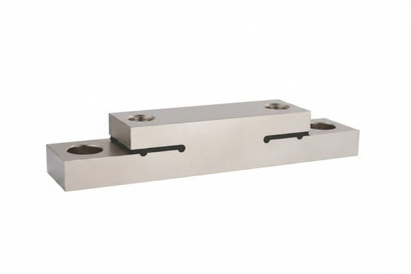
WST1406
- Emax 15 t, accuracy class 0.1 %
- Output 1.125 ± 0.005 mV/V, 384 ± 10 Ω in, 350 ± 3 Ω out
- Safe overload 200 % FS, ultimate 300 % FS
- Fully welded and sealed, IP68
- Repeatability < ±0.02 % AL, creep 30 min < ±0.020 % AL
- Fatigue life > 1 000 000 cycles at Emax, deflection < 0.5 mm
The one I reach for first on a body-on-chassis vehicle: the only IP68 part in the group, the widest overload margin, and a 350 Ω bridge that drops straight into existing vehicle electronics. The cost: its compensated window is only −10 to +40 °C even though it operates from −40 to +65 °C, so a cold-climate installation needs a disciplined empty-vehicle re-zero rather than an assumption.

WST1401
- Rated load 10 to 300 kN, about 1 to 30 t
- Combined error 0.02 to 0.05 % FS
- Sensitivity 2.0 mV/V, 750 ± 15 Ω in, 700 ± 5 Ω out
- Zero and output temperature effect ±0.02 % FS per 10 °C
- Creep ±0.02 % FS / 30 min, safe load 150 % FS
- −20 to +65 °C
The accuracy card, and the right part when the system has to return the same number for the same lift rather than an absolutely true one — loader payload scales, batching feed, target weighing. The cost: our page publishes neither an ingress protection rating nor an ultimate overload figure, so on an underside installation I quote both from the test record rather than from the datasheet.

WST1402
- Rated load 15 to 100 kN
- Combined error 0.3 to 0.5 % FS
- Sensitivity 1.5 to 2.0 mV/V, 750 ± 15 Ω in, 700 ± 5 Ω out
- Zero and output temperature effect ±0.05 % FS per 10 °C
- Creep ±0.05 % FS / 30 min, safe load 150 % FS
- −20 to +65 °C
Same mechanical family and the same bridge as the WST1401, an order of magnitude less error-sensitive, and materially cheaper. The cost: it is the wrong part the moment an application needs repeatability of a repeated lift — and it is the right part on any steel-spring vehicle, because there the suspension is already thirty times the error and paying for 0.02 % buys nothing. Same documentation gap on ingress protection and ultimate overload.

WST708
- Double-ended shear beam with gauges inside a drilled bore
- Replaces the existing hinge or shear pin without changing the machine
- 5 t at 0.77 ± 0.005 mV/V, or 7.5 t at 1.16 ± 0.005 mV/V
- Combined error ±0.5 % FS, repeatability ±0.1 % FS
- Safe overload 120 % FS, ultimate 150 % FS, IP67, all stainless
- Bidirectional, vibration and side-load resistant, 380 ± 30 Ω in
The part for a load path that already contains a pivot: put a sensor of the same envelope back into the bore and it sees exactly what the pin saw. The cost: safe overload is only 120 % FS, thin for a vehicle chassis, and its operating window is −10 to +40 °C even though its compensated range covers −35 to +70 °C — an inversion of what people expect. It also needs an anti-rotation feature designed in, not added later.
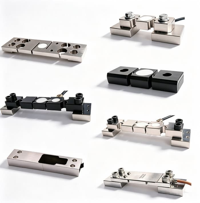
WST703
- Measures structural strain directly, 300 to 1 000 με
- Alloy steel or stainless steel body
- IP65
- For axle, chassis rail and frame deformation sensing
- Used where there is no pivot to replace and no pressure to read
- The only route to load data on a conventional leaf-spring vehicle
The device for the on-axle family: when there is nothing to pressurise and nothing to replace, deformation is the only signal available, and this is how you read it. The cost: our own page files it under silo weighing and structural monitoring and its address contains no model number at all — it lives at /product/micro-strain-sensor/ — so a search for “WST703” will not find it. IP65 is also modest for an underside position, which is why an axle-mounted version is a weather-protected installation, not a submersible one.
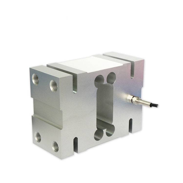
WST211
- Rated load 100 / 200 / 350 / 500 / 750 / 1 000 / 2 000 kg
- Accuracy class C3, combined error ±0.02 % FS
- Output 2.0 ± 0.2 mV/V, 406 ± 20 Ω in, 350 ± 5 Ω out
- Zero and output temperature effect ±0.017 % FS per 10 °C
- Safe overload 120 % FS, ultimate 150 % FS, IP65
- −20 to +80 °C operating, −10 to +60 °C compensated
A large parallel-beam single-point cell with excellent temperature behaviour, for light support points, access-platform weighing and maintenance positions rather than the main load path. The cost: it tops out at 2 t, so on a 20 t vehicle it is a corner or accessory part and not the weighing element; IP65 is again on the low side; and the excitation fields on our page are transposed — the labelled recommendation reads 18 V DC while the labelled maximum reads 5 to 12 V DC, which is the wrong way round.
16. Frequently asked questions
What is on-board weighing, and how is it different from a weighbridge?
A weighbridge measures the whole vehicle as a single mass, at a fixed location, usually to a legal standard, and it does so once. On-board weighing measures load where the load is carried, continuously, on the vehicle itself. The important consequence is that an on-board system can separate axle load and axle-group load, which a weighbridge reading of the gross total cannot do at all — and moving a load one metre along the deck can transfer more than a thousand kilograms between axle groups without changing the gross weight by a kilogram. That is the whole reason the category exists.
Can an on-board weighing system be legal for trade?
Sometimes, and it depends on your jurisdiction and how the weighing is performed, so I will not give a blanket answer. The lay of the land: OIML R76 covers non-automatic instruments including those mounted on a vehicle; OIML R51 covers automatic catchweighers and expressly includes instruments mounted on a vehicle that weigh automatically while it is stationary, which makes R51 the closest match that exists; OIML R134 states in its own scope that it does not apply to instruments installed on-board vehicles to measure axle load; and in the EU, MI-006 does not address vehicle mounting at all, while non-automatic instruments sit under a different directive. If legal-for-trade status is a requirement, that is a conversation with your national metrology authority, and it should happen before you buy anything.
What accuracy can I realistically expect from on-board weighing?
On the payload, somewhere between 0.4 % and 3 % depending on the vehicle, and the sensor is rarely the reason. Take a 20 t refuse truck with a 12 t tare: a four-cell chain at 0.1 % FS contributes about 0.41 % of the 8 t payload when its terms are combined root-sum-square, or 0.70 % if you add them worst case. Now add the suspension. Published repeatability figures for on-board load-sensing systems run from about 1 % of the load on air suspension to 5 % or even 7 % on steel leaf springs, which on an 11 500 kg driven axle is 230 kg to 805 kg — between nineteen and sixty-seven times the entire sensor chain. That is the number that determines your real accuracy, and no load cell purchase changes it.
Which suspension type is best for on-board weighing?
Air, by a wide margin, for two separate reasons. It repeats better — published figures put air at about 1 % to 3 % of the load at the axle against 5 % to 10 % for steel leaf springs — and it can be measured without touching the structure, because the bag already presents a pressure proportional to load. Steel leaf springs present nothing to measure, so the signal has to come from strain: a sensor replacing an existing pivot, or a micro-strain element where the structure deforms. If your fleet is all steel spring, spend the money on a reference vehicle and a proper in-situ calibration rather than on a precision cell. If it is mixed, you are buying two sensing technologies, and any supplier offering one part for both is guessing.
Should I use four load cells or a pin-type sensor?
Four cells under a rigid body give a better measurement; a pin gives a cheaper and mechanically simpler one. A pin-type sensor of the WST708 kind goes into a bore that already exists and sees exactly what the original pin saw, so there is no new load path to design and no new structural analysis. The trade is that a four-point body lets you see where the load is, and a single pin does not — and given that penalties are usually assessed per axle, seeing where the load is may be worth more than the accuracy difference. Check two things on a pin before you commit: that it cannot rotate, since a rotating pin destroys its own cable, and that its safe overload is adequate, since some pin designs publish only 120 % FS.
Why does my on-board scale drift over time?
Usually not the sensor, and usually not the electronics. Four causes dominate. First, the suspension changes as it ages — springs settle, air bags leak, dampers go off — and the system was calibrated against a vehicle that no longer exists. Second, thermal drift moves the zero: the recommendation allows one scale interval for every 5 °C, which on a 50 kg interval is 10 kg per degree for the whole chain. Third, the load path changes physically — a bracket loosens, a shim pack compresses, a crossmember cracks. Fourth, the indicator’s automatic zeroing quietly walks while the vehicle is loaded. Before buying anything, re-zero on level ground with the brakes released and the vehicle empty, run a five-point calibration in both directions, and compare it with the original record. That test tells you which of the four you have.
Can I also weigh individual bins or cans from the same load cells?
Not reliably, and this is the most common unrealistic request I receive. On a 20 t refuse truck a four-cell chain at 0.1 % FS has about 20 kg of uncertainty in the summed reading, while a wheelie bin is 30 kg — one and a half times the noise floor. The fix is not better cells; it is separating the two measurements. Take the per-bin or per-lift weight from the lift cycle itself, using hydraulic pressure or a differential reading against the body weight immediately before the lift, and keep the payload total on the load cells with a much longer averaging window. Two problems, two measurement chains, and the per-bin number becomes useful. If your weighing happens after the container has been set down rather than while it is on the vehicle, that is a different application entirely.
What do you need from me to quote load cells for on-board weighing?
Five things, and I will ask for them in this order. The gross vehicle weight, the tare, and the payload you actually sell. The axle limits on the routes the vehicle runs, because a gross-compliant truck can still be illegal on an axle. The suspension type — air, steel leaf, or something else — because that sets the accuracy ceiling before any sensor is chosen. A drawing or photograph of the mounting area with the candidate sensor positions circled, plus a note on how stiff the body is there, since a load cell measures the force where it is installed and nowhere else. And finally what decision the number drives: billing, overload prevention, or occasional verification. That last one changes the design more than any of the other four, and it is the question customers least expect to be asked.
Gross weight, tare, payload, suspension type, and a drawing of the mounting area with the candidate positions circled. I will come back with the force at that point, the range I would choose, the dynamic and overload margin that goes with it, the error budget expressed on the payload you actually sell, and a written statement of what I am not covering. If the number you sent me is the wrong one, you will hear that first.
VektorForce · load cells, force sensors, junction boxes and weighing indicators · www.vektorforce.com · Robin@vektorforce.com