
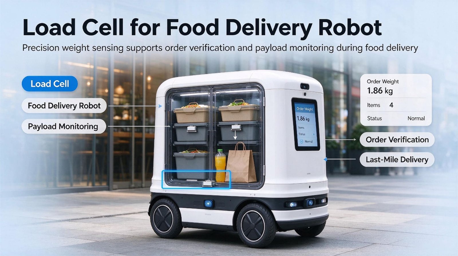
A delivery robot’s tray weighs presence, not dinner, and the door threshold sets the overload, not the meal.
A delivery robot does not need to weigh the meal. It needs to know whether the plate is still there — and the thing that decides your overload rating is not the dinner. It is the door threshold, crossed at one metre per second, with a tray full of porcelain on board.
10 kg per tray, 40 kg per robot
10 mm threshold = 3× apparent load
16 g floor vs a 3 g napkin
ISO 3691-4 · EU 2023/1230
RS485 digital cell, 2 g division
- Why a delivery robot does not need a scale
- Infrared is blind in space. Weight is blind in time.
- Four trays are not four scales
- The range is set by the door threshold
- Your guest’s hand is heavier than the plate
- You will see the plate. Not the napkin.
- The only number that matters is a difference
- The three degrees between kitchen and table
- A plausible number, or no number at all
- One cell in the middle, or four at the corners
- The datasheet promises minutes. The trip is 90 seconds.
- Nine questions that pick the cell
- Standards: what applies, what does not
- What I supply, and what I do not
- Questions I get from robot builders
- Five load cells I would shortlist
1. Why a delivery robot does not need a scale
I sell load cells for food delivery robots to the people who build the robots — not to the restaurants that rent them. My customers are the factories: the ones that weld the mast, cut the tray plates, write the navigation stack, and then discover that the last unsolved problem on the whole machine is a small metal part sitting under a tray.
Almost every enquiry starts the same way. Somebody has been burned by infrared tray sensors, or has read that they have blind spots, and has decided to “put a load cell on each tray instead.” That instinct is right. What is almost always wrong is the specification that arrives with it, because the specification is written as if the tray were a kitchen scale. It is not. A tray on a moving robot is the only weighing platform I supply that spends its entire working life on a vehicle, in public, with strangers touching it.
So let me state my side of the drawing before anything else, because it decides what you should even ask me for. I make the sensing chain: load cells, force sensors, junction boxes and weighing indicators. I do not build the robot, the mast, the tray plate, the drive train, or the navigation stack. I do not hold machine certification for your product, and I will not sign your risk assessment. What I can do is tell you, with arithmetic, which cell belongs on that tray, what it will and will not see, and where the honest limit of the measurement sits. Everything above that line — the CE marking, the safety functions, the site assessment — belongs to you and your notified body, and I will say so again in section 13.
The food delivery robot market was worth about USD 1.25 billion in 2025 and is projected to reach USD 5.81 billion by 2032, a compound growth rate of roughly 24.6 %. Indoor delivery robots accounted for 60.6 % of that in 2025, and restaurants and hotels made up 54.7 % of end use. The narrower restaurant robot market is put at USD 2 billion for 2026 growing to USD 6 billion by 2033, with meal-delivery robots taking 54 % of it.
Translated into my customers’ language: this is no longer a demo category. It is a category where somebody has to make 40,000 tray sensors a year without a returns problem. Figures are from the market studies linked at the end of this article, and they vary between sources — the direction is what matters, not the third digit.
The reason a robot factory calls me at all is that the tray is doing four different jobs at once, and they have all been given to one sensor without anybody writing the list down:
| The question the robot is really asking | What it needs from the sensor | What it costs you if you get it wrong |
|---|---|---|
| Is there anything on the tray? | A threshold that sits above the drift floor | The robot refuses to move, or drives off with a full tray |
| Did the guest take something? | A stable difference, measured at two moments | The robot returns to the kitchen, waits at the wrong table, or reports a loss that did not happen |
| Is it overloaded or leaned on? | Range and a hard mechanical stop, not accuracy | A permanent zero shift, then a stream of service calls that look like drift |
| Is the sensor still telling the truth? | A channel that can report its own failure | Silent wrong numbers for months, because nothing ever alarms |
One load cell can answer all four questions. It cannot answer all four at the same time, and it cannot answer them at the same accuracy. The rest of this article is about deciding which one you are allowed to get wrong, because that decision costs nothing and it is the difference between a tray sensor that works for three years and one that generates a support ticket every afternoon.
A tray sensor is not a measuring instrument. It is a state sensor for your state machine. Once you accept that, the specification stops being about accuracy and starts being about threshold, timing and survival — three things that are cheaper to get right than accuracy, and three things a datasheet will not tell you.
2. Infrared is blind in space. Weight is blind in time.
Here is the problem that put tray weighing on the roadmap of nearly every robot builder I work with, and I can state it from the source material my own industry circulates rather than from a customer’s complaint form.
Most delivery robots on the market detect whether something is on a tray with infrared proximity sensors. Infrared is a beam with a cone. Put a small plate down, or put the plate near the edge of the tray instead of in the middle, and the beam never crosses it. The tray is full and the robot reports empty. The robot then refuses to leave the pass, or leaves without the dish, or drives back to the kitchen to be reloaded. Either way, a human is pulled off another job to fix something a sensor got wrong. The failure is not random — it happens on exactly the objects a restaurant actually uses: a soup bowl, a sauce dish, a child’s plate, a tray of cutlery.
Weight sensing fixes that completely. Load a cell under the tray plate and it does not care where the bowl is, how small it is, or whether it is porcelain or glass. It sums. That is the whole pitch, and it is a good pitch, which is why I get asked for it.
But I have to be honest about what you have traded away, because the trade is not “bad sensor for good sensor.” It is a blind spot in space for a blind spot in time.
Infrared misses a small plate in a large tray. A load cell misses a large plate that was removed while the robot was driving, or a small plate that was removed after the zero point drifted by more than the plate weighs. And it misses them silently, with a number that looks perfectly reasonable. A robot that says “empty” when the tray is full is annoying. A robot that says “4.1 kg” when the tray actually holds 4.4 kg is dangerous, because you will build logic on top of it.
Everything in the next nine sections is a defence against that second failure mode.
| What you put on the tray | Fails on | Fails how |
|---|---|---|
| Infrared beam | Small items, items at the tray edge, glossy or transparent items | Says empty when loaded. Loud failure — someone notices within one trip. |
| Ultrasonic / ToF | Knows something is present, not what or how much; sensitive to steam and to the tray’s own geometry | Cannot tell “one plate” from “four plates.” Steam off soup is a real false trigger. |
| Camera / vision | Occlusion, lighting, and the tray’s own shadow; needs the whole stack plus a model | Right most of the time, wrong in a way that is hard to explain to a customer, and it costs compute and power. |
| Load cell under the tray | Reads nothing while the wheels are turning; cannot see anything lighter than its own drift floor | Says a number when it should say “I do not know.” Silent failure — nobody notices until the numbers are already in a dashboard. |
The row in red is the row I sell, and I have written it in the same table as the others on purpose. If you are choosing between these four because you want one of them to be obviously right, you will make a worse decision than if you choose two of them and make them disagree on purpose. The robots I see succeed use weight for quantity and a beam or a camera for identity, and they are wired so that a disagreement raises a flag instead of being silently resolved. If you want to see how that division of labour is done in unattended retail, where the same problem was solved years ago, the vending machine guide and the smart shelf guide are the two I hand out most often for this.
3. Four trays are not four scales
This is the first thing I check, and it is the thing that has cost my customers the most money. It is a mechanical question with a firmware symptom, and it arrives in my inbox described as a sensor fault.
Look at the class of machine you are building. The BellaBot carries four trays and 40 kg, so 10 kg per tray. Bear Robotics quotes the Servi Plus at 88 lb over three trays, or about 12 kg per tray. The Keenon T8 carries 20 kg across three trays, so roughly 6.7 kg per tray. Now the question that decides your entire sensor architecture:
Do the four trays sit on four independent load paths, or do they hang off one column?
On most of the robots I have been given drawings for, the trays are cantilevered off a single central mast. That is a sensible mechanical choice: it is stiff, it is cheap, it is easy to keep the trays level, and it puts the mass low. It is also a decision that means tray 3’s sensor is measuring tray 3 plus everything above it. Put a cell under each tray of that machine and you have not built four scales. You have built one scale with four windows onto the same number, and every one of those windows has a different leverage, a different cable, and a different zero.
| Tray architecture | What each sensor sees | What you get |
|---|---|---|
| A. Four independent cantilever arms each tray on its own arm, each arm on its own cell |
Its own tray, plus the small torsion its own arm transfers to the mast | Four real scales. Four channels, four cables, and a mast stiff enough not to couple them. |
| B. One column, one cell the whole tray stack on a single weighing point |
The total of all four trays | One honest number: what is on the robot. You cannot say which tray changed. |
| C. Half-separated four cells, but the trays share a mast and touch each other |
Mostly its own tray, plus a fraction of its neighbours’ load, varying with how the plates are distributed | Four numbers that all move together. Your firmware reads cross-talk as theft, and you will spend a quarter chasing a sensor problem that is in the welding drawing. |
I have watched architecture C cost a customer a full hardware revision. The symptom was described to me as “the lower sensors are noisy” and the request was for a tighter tolerance part. The request was wrong. The lower sensors were reading correctly — they were reporting a load change, because a load change really had occurred at the top of the machine, and the mast was transferring it. No tolerance I can hold on a strain gauge changes that.
Not the sensor drawing. The tray assembly drawing, with the load path marked. I want to see which part touches which part, from the plate down to the chassis, and I want to see where the mast ends and the tray begins. Nine times out of ten, that single drawing tells me whether the customer needs four cells or one, and it is a different answer from the one they wrote in the email.
If you cannot get a drawing, a phone video of one tray being loaded while you watch the other three readings is almost as good. I have diagnosed architecture C twice from video. If your electronics do not publish per-tray readings anywhere you can watch, that is itself the first thing to fix.
There is one more version of this trap that nobody expects, and it shows up when the trays are right. If your top tray is removable and docks into a bracket, then the bracket is a second load path the moment the tray is slightly twisted or the locating pin is worn. The cell underneath then measures a fraction of the tray, and the fraction changes as the dock wears. The zero-cost test for that is in section 10, and it takes about thirty seconds.
The same stacking logic governs a great many machines that are not robots at all. If you want to see it worked through on a locker bank, a shelf, or a set of drawers where each compartment has its own cell and they all share a frame, the smart locker guide covers the same failure with the same arithmetic.
4. The range is set by the door threshold
Ask a robot builder what the tray has to carry and you will get a menu. Ask them what the tray has to survive and you will get a pause. Those are two different numbers, and the second one is bigger. Here is the arithmetic I do on a call, out loud, because it is faster than waiting for a reply.
A four-cover tray in a mid-market restaurant: a 26 cm porcelain dinner plate at about 600 g, a rice bowl at 450 g including contents, a glass at 250 g, and a wrapped cutlery set at 80 g. That is 1,380 g per cover. Four covers is 5,520 g, and the tray plate itself — the aluminium or ABS panel the cups actually sit on — adds about 1,200 g. So a loaded tray in my design case is 6,720 g, which is 44.8 % of a 15 kg cell. Comfortably inside the 30–60 % working band I like, with room for a coffee pot on top.
Now the number that actually sizes the part. Your robot weighs it does not matter how much; what matters is that it rolls. A caster crossing a 10 mm threshold at walking speed is a small vehicle falling off a small kerb, and the tray experiences it as a vertical acceleration pulse. The impact speed is 0.443 m/s — that part is fixed by the height. What you control is how far the machine takes to absorb it, and that is where the cell’s fate is decided.
| Absorption distance after a 10 mm drop | Deceleration | Apparent weight of a 6.72 kg tray | Against a 15 kg cell |
|---|---|---|---|
| 20 mm — soft rubber caster, air in the tray mounts | 0.50 g | 10.1 kg | 67 % — nothing to do |
| 10 mm — hard wheel, rigid mount | 1.00 g | 13.4 kg | 90 % — still inside, no margin left |
| 5 mm — steel-on-steel, no compliance | 2.00 g | 20.2 kg | 134 % — past the 150 % safe line on a bad day |
| 2 mm — cell bolted straight to the plate | 5.00 g | 40.3 kg | 269 % — the cell is now a fuse |
Read the last column again, because it is the whole point of this section. A 15 kg cell lives comfortably at 20 mm of compliance and dies at 2 mm, on exactly the same tray, carrying exactly the same dinner. The part number did not change. The bumper did. If you want the 15 kg cell to stay inside its 150 % safe overload through a 10 mm threshold, you need at least 20 mm of absorption somewhere between the wheel and the load axis. That is a design instruction, not a sensor specification, and it costs a few euros of elastomer.
The second load case is the human one, and it is static, which makes it worse. A relaxed hand on the tray edge is about 0.4 kg — harmless. But a person who steadies themselves while standing up transfers more than they think they do. At 10 % of body weight a 70 kg adult puts 7 kg through that hand, taking a 6.72 kg tray to 13.7 kg, or 91 % of a 15 kg cell. At 25 % — a proper lean — it is 17.5 kg, taking the total to 24.2 kg, which is 161 % of the 15 kg cell and past its safe overload.
A 30 kg cell solves it arithmetically and costs you precision, as section 6 shows. A hard mechanical stop solves it for the price of two screws, by making sure the last millimetre of travel is carried by the frame and not by the beam. If you take one hardware idea from this article, take that one.
There is also a free fix, and I push it harder than any part number. Your navigation stack already knows, to the millisecond, when the robot is moving and when it has settled. Do not read the tray while it is moving, and do not act on a reading taken during the first second after it stops. That single rule removes the entire shock table above from your error budget, because the impact only exists while the wheels are turning. I have watched it turn a tray sensor that “jumps constantly” into one that never misses a plate. Nothing was purchased.
A weighing platform on a moving vehicle is not a harder version of a weighing platform on a floor. It is a different instrument with a different specification. The instrument is a weighing system: a cell, a mount, and a rule about when the number is allowed to be believed. I supply the first, I argue about the second, and the third one is free and belongs in your firmware.
5. Your guest’s hand is heavier than the plate
The question the robot is trying to answer at the table is “did something leave the tray?” The sensor does not see a departure. It sees a number go down. And there are at least three different things in a dining room that make the number go down:
Somebody took the plate. Somebody rested a hand on the tray and then took it off. Or the tray cooled by two degrees because the robot has been standing near a window. The first two produce amplitudes in the same range. The third produces a drift that is smaller than either, which sounds reassuring until you remember it accumulates over a shift.
| What actually happened | Change on the tray | How long it lasts | Visible in amplitude? | Visible in time? |
|---|---|---|---|---|
| Guest takes a full plate | −850 g | Permanent | Yes — 53× the floor | Yes — it stays |
| Guest rests a relaxed hand | ±400 g | 1–3 s | Yes — half a plate | Yes — it comes back |
| Guest steadies herself on the tray | +7 to +17.5 kg | 0.5–2 s | Yes — 8 to 21 plates’ worth | Yes — it comes back |
| Tray cools by 3 °C | −4.5 g | Minutes | No | No — looks exactly like a slow removal |
Look at rows two and three. A hand and a plate produce amplitudes that overlap: a relaxed hand is 400 g, half of what a plate weighs, and a person steadying themselves is twenty times a plate. There is no threshold you can set on amplitude that separates “took a plate” from “put a hand down,” because the hand can be lighter than the plate and heavier than the plate, depending on the guest. This is the point where a lot of builders go shopping for a better sensor, and it is the wrong shopping trip.
A hand goes on and comes off. A plate goes and stays gone. So the rule your firmware needs is not “the weight changed” but “the weight changed and stayed changed” — a persistence window of 2 to 5 seconds with the robot stationary. That single line of logic does more for your false-alarm rate than any cell I could sell you, and it costs nothing.
The price is dwell time at the table. A 2 second window on top of the 8–15 seconds the robot already spends waiting for guests is a 13–25 % increase in that stop. A 5 second window is 33–62 %, and it will also merge two fast removals into one event. Two seconds is where I would start, and I would measure it in your own dining room before I believed either of us.
One more thing about the hand, and it comes up on every single project. If your tray logic removes the hand’s weight by using a moving average or a slow filter, you will also be removing the plate, because the plate’s change is not much faster than the hand’s. Filtering is a trade, not a setting. I have seen a robot that reported a perfectly smooth tray weight all evening and never once noticed that the plates had left, because the filter time constant was longer than the guest’s visit. If your stability looks beautiful, check whether it is still telling the truth — that specific failure is written up in more detail in the fault-finding walkthrough.
6. You will see the plate. Not the napkin.
This is the most valuable calculation in the article and it takes ninety seconds. The question is never “how accurate is the sensor.” It is “how small a change can this sensor see, given everything else that is moving.” That number is a floor, and it has three parts.
| Contribution to the floor | Source | On a 15 kg WST101 | Share |
|---|---|---|---|
| Comprehensive error | 0.05 % F.S — non-linearity, hysteresis and repeatability together, as published | 7.5 g | 48 % |
| Zero thermal drift | ±0.1 % F.S / 10 °C, over the 3 °C the tray actually sees between the pass and the table | 4.5 g | 29 % |
| Creep | 0.05 % F.S / 3 min, read over the 90 seconds the tray is actually loaded | 3.75 g | 24 % |
| Floor, worst case added | What the tray can resolve on a bad afternoon | ≈ 16 g | 100 % |
Add the three rows and you get 7.5 + 4.5 + 3.75 = 15.75 g. I round that up to 16 g on purpose, because a floor is a worst case and it should never be quoted optimistically to a customer who is about to write firmware against it.
Now put the actual objects against that 16 g floor. This is the table I send back when somebody asks me for a tray sensor that can detect a napkin.
| What leaves the tray | Mass | Multiple of the floor | Verdict |
|---|---|---|---|
| Dinner plate with leftovers | 850 g | 53× | Trivial. You will never miss one. |
| Empty glass | 250 g | 16× | Comfortable, with the wheel rule applied |
| Wrapped cutlery set | 80 g | 5× | Detectable, but do not build a rule on it alone |
| Paper napkin | 3 g | 0.19× | Below the floor. You cannot see it, and no cell I sell changes that. |
I have had this exact request three times. Each time the answer was the same: the napkin is 0.19 times the floor the tray can resolve, so any “napkin detection” feature you ship will actually be detecting temperature, creep and caster vibration. It will pass your test bench and fail in a dining room. If a product requirement genuinely depends on 3 gram resolution on a moving 15 kg platform, the requirement is the problem, not the catalogue.
The mirror image of this is the one that costs real money, so it is worth stating plainly. Over-sizing the cell makes the floor worse, not better. Take the same 0.05 % F.S part and buy it in 30 kg instead of 15: the floor goes from about 16 g to about 31.5 g, and the cutlery set drops from 5× the floor to 2.5×. You paid more and bought a tray that can no longer see a spoon. This is the same trap I have written about for hopper scales and for mixer cradles, and it is the reason I keep a plain-language selection guide rather than a catalogue on my desk.
I am proposing WST103 in this article as a low-capacity option for small counter-top tray machines, because it is a genuinely good small cell. But if you build a 20 kg tray on it, its zero thermal drift is ±0.2 % F.S per 10 °C — four times looser than WST1101’s ±0.05 %. Over the 6 °C between a cold morning and a hot lunch service that is 24 g of zero movement, against 4.5 g for the tighter part. It appears on my own website marked as a hot-selling model, which is true and irrelevant. Hot-selling and well-matched are not the same sentence, and on a tray that has to see a glass, they are different products.
I would rather tell you that here than have you find it in a returns report six months after launch.
7. The only number that matters is a difference
Now I am going to give you the single largest improvement available to your tray system, and it is a change of question rather than a change of hardware. It comes from the fact that nobody pays for the meal by the kilogram. Your robot does not price anything. It is not a legal measuring instrument, it will never be inspected as one, and the absolute mass on the tray is a number that no customer, no accountant and no regulator ever asks you for.
What the robot actually needs is this: what did I leave the kitchen with, and what came back? Two readings, taken on the same tray, minutes apart. Everything interesting lives in the difference between them.
The 16 g floor I calculated in section 6 is not three independent errors that you can average away — the comprehensive error is a property of the part and it is present in both readings. Take the departure reading and the arrival reading and subtract them, and the part’s comprehensive error largely cancels, because it is the same part, the same beam, the same load direction and the same temperature band.
What does not cancel is the drift that happened between the two readings. Over a 90 second trip with a 3 °C swing, that is 4.5 g of thermal zero movement plus 3.75 g of creep, or about 8.25 g. So the difference is good to roughly 8 g while the absolute reading is only good to 16 g — a 1.9× improvement, free, from choosing the right question. Suddenly an 80 g cutlery set sits at 10× the floor instead of 5×, and you can build on it.
There is one condition on that improvement, and it is the reason this section exists.
The two readings must share the same zero. The moment your firmware performs an automatic zero-set between them, you have broken the only thing that made the subtraction good. Every product I have seen with a mysterious “weight creep” complaint has had an auto-zero somewhere in it, and every one of them had it for a defensible reason: settling after boot, saving a service call, handling a bumped tray.
| Zero-set policy | What it buys | What it costs |
|---|---|---|
| Zero at every boot | Removes the previous shift’s thermal offset | Nothing, if the tray is genuinely empty and still. This one is fine. |
| Zero whenever the reading is below a threshold | Hides slow drift from the operator | If anything is on the tray that is lighter than the threshold, you have just taught the robot a false truth — permanently, silently, and consistently. |
| Zero on a timer, at any load | Nothing at all | It deletes real removals from the difference. Your “traffic” data becomes a record of your own firmware. |
Every other error in this article is mechanical, thermal or electrical, and I can quote you a number for it from a datasheet. This one is different: it is a decision, it is invisible in the data, and it makes the result more consistent rather than noisier. A tray that has been mis-zeroed by 250 g will report every subsequent change correctly and every absolute value wrongly, forever, with no alarm. If you build reporting on it, you will publish a loss figure that never happened.
The version of this rule I now recommend by default has three conditions, and all three have to be true before the zero moves:
- The tray reads empty — below a low threshold that is comfortably above the 16 g floor, say 100 g.
- The robot reports settled — it is not moving and has not moved for at least one second.
- Nothing has changed for five seconds — no removal, no hand, no impact.
With those three conditions, the auto-zero can only fire on an empty, still, undisturbed tray, which is exactly the only state in which the reading you are overwriting is known to be meaningless. The rule is free, it is entirely yours, and it removes a whole class of customer complaint that would otherwise land on my desk.
The machines that have solved this problem most cleanly are not robots. They are refrigerated cabinets and appliance panels, which have to survive exactly the same argument — a slow thermal drift, a lid opening and closing, and a user who expects the number to be right. The connected home weighing guide and the tank weighing guide both spend most of their length on zero policy rather than on accuracy, and that is not an accident.
8. The three degrees between kitchen and table
A delivery robot has the most varied thermal life of any machine I sell into. It starts in a cold service corridor, passes through a pass where heat lamps are running at 60 °C, waits under a lift’s air conditioning, then stands next to a diner’s table in a warm room. None of that is dramatic. All of it moves the zero, because the zero moves with temperature on any strain gauge cell, and the amount is published in percent of full scale per ten degrees.
| Model and capacity | Zero drift per 10 °C | Over the 6 °C of a full service day | Versus a glass (250 g) |
|---|---|---|---|
| WST1101 @ 15 kg | ±0.05 % F.S | 4.5 g | 1.8 % of the glass |
| WST101 @ 15 kg | ±0.1 % F.S | 9 g | 3.6 % |
| WST103 @ 20 kg | ±0.2 % F.S | 24 g | 9.6 % — a tenth of a glass |
| WST1204 digital @ 60 kg | ±0.002 % F.S per °C — ±0.02 % per 10 °C | 7.2 g | 2.9 % |
Read the digital row against the WST1101 row and you will find the trap in this table, because it nearly caught me. In datasheet units the digital cell is the best part here — 0.002 % of full scale per degree is 0.02 % per ten degrees, two and a half times tighter than WST1101’s 0.05 %. In grams it is not, because the smallest WST1204 I build is a 60 kg cell and the cell it is being compared against is a 15 kg cell: 7.2 g against 4.5 g over the same six degrees. Percent of full scale is the wrong unit when the full scales differ by four. If you buy the tighter specification and keep the bigger capacity, you buy the better datasheet and the worse tray.
Then look at the ratio between WST1101 and WST103, which is the comparison that actually changes a design. WST103 looks like the cheaper, smaller, more appropriate part for a light tray, and mechanically it is. But its zero drifts 5.3× as much as WST1101’s over the same temperature change, and on a 20 kg tray that is 24 g of movement against 4.5 g. If your tray logic is looking for a glass, that difference matters more than any consideration of price. If you only ever need to know “is the tray loaded, yes or no,” it does not matter at all. This is the same trade I describe for coffee machine shot scales, where the quantity being measured is smaller than the quantity drifting.
One honest refinement, because it changes how you should use the table rather than how much you should fear it. Thermal drift has a time constant. A 12.7 mm aluminium beam plus a 1.2 kg tray plate plus a steel frame does not reach a new equilibrium in ninety seconds; it takes minutes. So within a single 90-second delivery, the tray sees only a fraction of the steady-state figure. Across a shift, from a 22 °C morning to a 28 °C lunch service, it sees all of it. That is why the zero policy in section 7 distinguishes between “zero at boot” — which removes the shift-level offset — and “zero on a timer” — which does not help and destroys your differences.
A heat lamp over a pass radiates directly onto the tray plate, and the tray plate is the thing your cell is bolted to. Radiant heating is not ambient temperature, and neither you nor I have a coefficient for it, because it depends entirely on how long the robot waits under the lamp. What I can tell you is that waiting time at the pass is the most variable number in the whole duty cycle, and it is the reason I ask for a 24-hour log of the tray reading with no food on it before I will promise anything about threshold behaviour on a specific machine.
If your robot works across floors, add the lift to that picture. Lift cars are air-conditioned to a different set point than a service corridor, so a multi-floor robot can accumulate a real thermal cycle on every trip rather than once a shift. On the machines I have helped with, this showed up exactly as you would predict: the first deliveries after a change of floor were slightly off, and then everything settled. It was never a sensor fault, and no part change would have fixed it. If your tray is holding a patient’s meal or a medicine tray instead of a restaurant order — the hospital version of this same machine — the tolerance conversation gets stricter and the medical device notes are the better starting point than this article.
9. A plausible number, or no number at all
Every tray sensor I have discussed so far is an analog strain gauge bridge. You power it, it returns a couple of millivolts, and somebody downstream has to convert that into a number. On a bench that is trivial. On a service robot it is the hardest part of the job, and it has nothing to do with the sensor.
Here is what that analog chain looks like on a real machine. Four cells, one per tray. Four sets of signal wires, each a few hundred millimetres long, routed from a tray that moves to a chassis that holds the electronics. Those four signals have to be summed, corner-matched and then digitised, and the digitiser has to live somewhere on the robot. On almost every robot I have seen, “somewhere” is the main electronics bay, which is also where the motor drives are. A brushless drive switching at 20 kHz is a radio transmitter sitting a few centimetres from a 1 mV signal. The cell is innocent. The layout is the fault. When that goes wrong, you get a reading that is plausible and wrong — and an analog cell has no way at all to tell you it is being lied to.
There is a second family of part that removes that entire problem, and it is why I am proposing WST1204 in this article even though it is a bigger, more expensive cell than the tray needs. In a digital cell, the amplifier, the analogue-to-digital converter, the calibration and the protocol stack all live inside the sensor housing. What comes out of the sensor is not millivolts. It is an RS485 or RS232 frame.
| Question | Four analog cells into the robot | One WST1204 digital cell |
|---|---|---|
| What crosses the moving joint | Four low-level analog signals, or four cables and a summing box | One 4-wire cable, one address on an existing bus |
| Where the ADC sits | Inside the robot, in the same bay and often on the same rail as the drive electronics | Inside the sensor, screened by its own housing, 1.5 m from the drive |
| Division value | Whatever your own ADC noise floor allows | 1 g below 50 kg, 2 g at 60–100 kg, from a 300,000-count converter sampling at 1,200 times per second |
| Calibration | Corner-matching in your factory or at the customer’s site, with a reference mass | Done at my factory, including eccentric-load compensation, and it survives a change of gravitational acceleration |
| How it fails | A plausible number. Lengthy debugging with a camera pointed at the cell cable. | A frame that fails its checksum. Your firmware knows in 3 milliseconds. |
On a robot, the second one is far easier to survive. A robot that knows its tray sensor is not answering can stop, park, flag itself for service and keep the fleet running. A robot that trusts a plausible wrong weight will drive a full tray back to the kitchen and log a removal that never happened, and it will do it every day for a year without telling anybody.
That is the real argument for going digital on a tray. Not precision. Diagnosability. The 2 g division is a bonus, and it is a bonus roughly the size of my entire analog error floor — but it is not the reason.
It is worth being precise about where the digital cell wins and where it does not, because I would rather you bought the right one than the impressive one.
| Choose digital (WST1204) when | Stay analog when |
|---|---|
| The whole tray stack goes on one weighing point, so 60 kg and a 400 × 400 mm platform fit the job | Each tray needs its own independent cell and the payload per tray is under 15 kg |
| Your controller already speaks MODBUS RTU and you would rather add an address than an ADC | You have a clean analog front end, a short screened run, and no drive electronics anywhere near it |
| You want the sensor to be replaceable in the field without a calibration procedure or a reference mass | You need the tail of the signal before the converter, and you have your own filtering and diagnostics |
| Diagnosability matters more than unit cost, which on a USD 10,000–16,000 robot it usually does | The unit cost is the binding constraint and the machine never ships without a service technician |
Two practical notes on the digital route, from projects rather than from the datasheet. First, the digital cell is a bigger part — a 60 kg platform cell is not something you tuck under a single dinner tray, so this is a whole-machine decision, not a per-tray one. Second, because it outputs a number rather than a voltage, your acceptance test changes: you can no longer put a scope on it, so you want the sensor’s own diagnostics and a documented protocol from day one. If you are building the sort of machine where sensors are read over a bus and logged centrally, the same architecture appears in warehouse and AMR weighing systems and in packaging lines, and both of those write-ups deal with the wiring discipline in more depth than I can here.
10. One cell in the middle, or four at the corners
Section 3 was about the tray stack. This one is about a single tray, and it is the question asked immediately after the stack question is settled. There are only two sane answers, and a great many machines are built with an accidental third one.
| One cell, centre-mounted | Four cells, one per corner | |
|---|---|---|
| What it demands mechanically | A tray plate stiff enough to carry an off-centre plate without deflecting into a second contact point | A rigid plate and a frame that distributes load predictably to all four corners |
| Channels into your controller | One | Four, or one after a summing junction |
| Cables across the moving joint | One | Four, or four plus a run back from the summing box |
| Corner matching | Handled inside the cell, including eccentric-load compensation on the digital parts | Your problem. Four readings must be made to agree at one reference mass, and the frame’s stiffness has to cooperate. |
| Platform size limit | Real. A single-point cell has a platform it can carry without corner error. Beyond it, you need the four-corner route. | Effectively unlimited — this is exactly what planar-beam cells are for |
| The accident | Four cells, but the tray plate also rests on the frame at the middle or at one edge. The plate is now partly carried by the structure, every corner reads low, the numbers move when the plate is nudged, and the whole system stays beautifully repeatable while being wrong. This is the failure I find most often, and it is invisible in any single reading. | |
Load the tray with a realistic weight — two or three full plates is better than a neat reference mass here. Then take a strip of paper, or a thin feeler gauge, and work it into every gap between the tray plate and the structure underneath: the centre boss, the four corners, the locating pin, the cable grommet.
If the paper slides in and out freely, the cell is carrying the load. If it is pinched, the structure is carrying part of it. Slide one sheet under, then add a second plate to the tray and check the paper again — a second path frequently appears only when the plate deflects under load, which is why an empty test passes and a loaded machine misbehaves.
I have used this on mixer cradles, on appliance panels and on robot trays, and it has found a real problem in roughly half of the cases where somebody had already decided to buy a new sensor.
There is a slower version of the same fault, and it is specific to robots because a robot tray gets removed and refitted constantly. If the tray docks into a bracket with a locating pin, the pin and its hole wear. Over a few thousand cycles the tray sits a fraction of a millimetre differently, which means the fraction of the load going through the bracket versus through the cell changes, which means your zero moves a little every week and your sensitivity moves with it. The symptom is a machine that needed recalibration every service visit and nobody could say why. The fix is to make the bracket idempotent — a taper, a positive stop, a dowel rather than a slot — or to stop having a removable tray in the load path at all.
And the cable. It is the part of a tray system that fails first, it is never in the datasheet, and it is worth a paragraph because it is entirely within your control:
| Duty | Flex cycles in three years | What it means |
|---|---|---|
| Hotel room service, 40 trips a day | ≈ 44,000 | Comfortably inside the life of a good flexible cable |
| Busy restaurant, 300 deliveries a day | ≈ 270,000 | Still survivable, but only with a defined bend radius, a strain-relieved fixed point, and a service loop that flexes rather than pulls |
| Any duty, if the cable is cable-tied to the tray | Fewer, then open circuit | The cable is now carrying load. That is a second load path made of copper, and it will also break. |
A hundred thousand to a million cycles is the order of magnitude a properly routed multi-strand cable handles at ten times its diameter bend radius, so 270,000 cycles is a design you can ship — but not one you can ship with the cable hanging loose. Everything about tray weighing that goes wrong after eighteen months goes wrong at the cable or at the bracket, and both are cheap to fix on the drawing and expensive to fix in the field.
11. The datasheet promises minutes. The trip is 90 seconds.
Every cell I sell publishes a creep figure, and every one of those figures is quoted over a time base. When I first started quoting these parts to robot builders, I would put the creep numbers in a table and rank them, and I was wrong to do it. Look at what the three analog models in this article actually promise:
| Model | Creep, as published | In grams, on its own capacity | Over the 90 s the tray is loaded |
|---|---|---|---|
| WST101 @ 15 kg | 0.05 % F.S / 3 min | 7.5 g / 3 min | 3.75 g |
| WST1101 @ 15 kg | ±0.02 % F.S / 5 min | 3 g / 5 min | 0.9 g |
| WST201 @ 15 kg | ±0.02 % F.S / 30 min | 3 g / 30 min | 0.15 g |
| WST1204 @ 60 kg | 0.018 % F.S / 30 min | 10.8 g / 30 min | 0.54 g |
Four parts, three different time bases — three minutes, five minutes, thirty minutes. The percentage figures cannot be ranked against each other, because creep is not linear and a part measured over thirty minutes is not being held to a looser standard, it is being described over a longer window. A 0.018 % over thirty minutes is not the same promise as a 0.02 % over thirty minutes in the same way that 0.05 % over three minutes is a tighter restraint per minute. This is the third time in this series that I have had to warn a customer about comparing numbers across my own pages, and it is the reason I now convert everything to grams at the actual dwell time before I let anybody look at a table.
Once you convert, creep is between 0.15 g and 3.75 g over a real trip — a fifth of the floor in the worst case and a hundredth in the best. Meanwhile the thermal zero drift over the same 90 seconds is 4.5 g, and the comprehensive error is 7.5 g. Creep is the third-smallest term in the budget. If a supplier is selling you a tray load cell on the strength of its creep figure, he is selling you the term that was never going to be your problem. Spend the same money on the mount and the zero policy.
The one place creep does appear on a robot is the case that looks like creep and is not. A tray that reads a few grams heavy for the first ten minutes after a shift change, and then settles, is usually not creeping — it is the tray plate warming up, or the caster suspension taking a set after being parked overnight, or the pass heat lamp doing what heat lamps do. This is why the diagnostic I keep asking for is a tray log with nothing on the tray. Twenty-four hours of an empty tray tells you the entire zero behaviour of the machine: the thermal cycle, the settle time after boot, the effect of the robot going outside, and whether anything is genuinely creeping. I have never seen a customer produce that log and still disagree with me about the cause.
12. Nine questions that pick the cell
These are the questions I ask, in the order I ask them, because the earlier answers change the later ones. The first four decide about eighty percent of the specification. If you can answer them, I can quote you a part and an overload case in the same reply.
| # | Question | What it changes |
|---|---|---|
| 1 | Do the trays sit on independent load paths, or on one column? | The whole architecture. Four cells or one; four channels or one number. |
| 2 | Is the tray reading used anywhere in a safety decision — stopping the machine, locking a lid, allowing a door to close? | Whether I can help you at all. If yes, that function needs a rated architecture and a risk assessment, and that is yours, not mine. See section 13. |
| 3 | What is the smallest removal you must detect, and how sure must you be? | The threshold, which is the only specification that matters. A glass is a different product from a napkin. |
| 4 | What does the controller do with a tray reading while the robot is moving? | Whether most of your overload cases exist at all. Gating on motion is free and removes the shock problem. |
| 5 | What is the largest thing a human being will do to that tray — a hand, a lean, a child? | Capacity and the hard stop. Usually sets the range, not the menu. |
| 6 | What temperature does the tray see across a shift, and is there a lit pass or a heat lamp in the route? | Which zero-drift grade you need, and therefore which model. |
| 7 | Analog signal into your own converter, or a bus with an address? | Where the ADC lives, and whether the sensor can report its own failure. |
| 8 | When the tray reading is wrong, what should the robot do — stop, or carry on? | The failure direction you design for. This decides your threshold and your persistence window. |
| 9 | Has any decision in the product been built on this weight — billing, theft reporting, staff scheduling? | Whether the whole exercise has quietly become legal metrology. If money is derived from the number, the answer is yes and the rules change completely. See section 13. |
Question 9 is the one I will not let go, because it turns the honest frame of this whole article upside down. Everywhere else I have told you the absolute value does not matter. If a robot is weighing food that a customer pays for by weight — a buffet robot that charges for what you took, a self-service machine that bills per hundred grams — then the number is the price, an error in it is a trade dispute, and none of the “threshold and timing” logic in sections 5 to 11 is a defence. That is a different machine with a different legal framework, and I would rather you found that out during specification than during certification.
13. Standards: what applies, what does not
Food delivery robots are machinery, and in Europe the machinery rules changed recently. This section is what the framework looks like from where I sit — which is at the component level, supplying a sensing element. I am not your compliance route and I will not pretend to be, but I do want you to know which documents you are going to be asked for, because the conversation almost always starts with the wrong one.
| Instrument | What it is | Who owns it |
|---|---|---|
| Regulation (EU) 2023/1230 | The new Machinery Regulation, applying from 20 January 2027 and replacing Directive 2006/42/EC. It pays explicit attention to autonomous mobile machinery. | You, the machine manufacturer. Nobody downstream can take this over. |
| ISO 3691-4:2023 | Industrial trucks — safety requirements and verification, Part 4: driverless industrial trucks and their systems. This is the C-type standard that covers AGVs, AMRs, delivery bots and automated cart systems, and it is the one buyers actually ask about. | You, plus your integrator for site-specific routing and zones |
| ISO 13482 | Service robot safety, covering mobile servant robots that work in contact with people. A revised edition is in draft, extending the scope toward professional and commercial service robots. | You |
| EN ISO 12100 / EN 60204-1 / EN ISO 13849-1 | Risk assessment principles, electrical equipment of machines, and the performance-level rules for safety-related control functions. Together these are what a lid interlock or a tray-based stop has to satisfy. | You |
| EMC Directive 2014/30/EU with IEC 61326-1 | The emissions and immunity rules that apply to your robot as a whole. My cells are passive components; they neither emit nor are required to be marked. | You, on the assembled machine |
| RED 2014/53/EU and FCC Part 15 Subpart B | Radio equipment, because your machine carries Wi-Fi, LTE or a wireless link for fleet management. Nothing to do with the tray. | You |
| UL 3100 | The North American counterpart for automated guided vehicles, increasingly requested by US buyers alongside the ISO route. | You |
| LVD 2014/35/EU | Not applicable to my part. The cells in this article run on 3–15 VDC. The low-voltage directive starts well above that, so nobody should be asking me for a declaration under it. | Correctly, nobody for the cell itself |
| NAWI 2014/32/EU, MID, OIML R76, EN 45501 | Not applicable to a robot that does not charge by weight. The moment a robot bills a customer for the mass it carried, that changes, and it changes completely — the readings become a price and the machine becomes a regulated instrument. | You, and only if you go there |
| OIML R60 | A component-level standard for load cell metrology. It describes what a cell does; it certifies nothing about your machine. Every cell in this article is specified against it, and that is the whole of the claim. | Me, at the component level, and I keep it there |
I supply load cells, force sensors, junction boxes and weighing indicators, with the matching test data for each batch. That is the sense of “weighing solution” I can stand behind: the part, the electrical interface, the overload case and the arithmetic that goes with them.
I do not supply the robot, the mast, the tray plate, the mount, the drive system, the navigation stack or the firmware; I do not hold machine certification for your product; and I do not sign risk assessments. If the tray reading ever becomes part of a safety function, that function belongs to your design and your notified body, and the honest thing for me to do is hand you the repeatability figure and get out of the way.
One practical note for those of you exporting into the EU from Asia: the regulatory chain begins with the person or company established in the Union who takes responsibility for the machine on the market. Buyers are now asking for that before they ask for a specification. It is worth having an answer ready, and it is not something I can provide for you.
Two things about ISO 3691-4 that catch people out. First, it is a floor and not a ceiling — it names a list of hazards it does not cover, noise and vibration and explosive atmospheres among them, and your integrator is expected to layer the rest on top. Second, the machine’s CE marking does not cover the site. As soon as your robot calls a lift or drives through an automatic door, that interface becomes a safety question about the building, and somebody has to own it. Neither of those is a load cell problem, and both of them are the reason a tray sensing project can be perfectly specified and still stall for a quarter at the handover.
14. What I supply, and what I do not
The right-hand column is not a list of things I am apologising for. It is the reason the left-hand column is worth anything.
| What I supply | What I do not |
|---|---|
| Load cells and force sensors — analog strain gauge, and digital with RS485 / RS232 output | The robot chassis, the mast, the tray plates and the drive system |
| Junction boxes, summing and corner-matching for multi-cell trays, where you want analog | Navigation, obstacle avoidance, SLAM, fleet management or the app |
| Weighing indicators for bench, kit and service work | Firmware, thresholds, persistence windows or zero policy — I will argue about them, but I will not write them |
| Capacity, overload and working-point selection, with the arithmetic shown | The mechanical design of your mount, your bump stop or your tray docking |
| Batch test data, matched output sets for multi-cell designs, and screening bands on request | Machine CE marking, ISO 3691-4 verification, ISO 13482 assessment, or the EU authorised-representative role |
| Customised mounting holes, load holes and cable lengths on the miniature cells | Safety-rated components, safety functions, or a signature on your risk assessment |
| A candid answer about which of my own models is the wrong one for your job | Food-contact compliance for your tray surfaces, and hygiene approval for your machine |
That last row on the right matters more than it looks, because trays and food are in contact for eight hours a day and somebody will eventually ask you about cleanability. A load cell sits behind the tray plate; it is not a food-contact surface and it never should be. If your tray surface has to meet a food-contact requirement, that is a question for the plate material and the supplier of the plate, not for the cell under it. What I can do is tell you what protection the cell itself has, so that washdown and steam cleaning do not quietly destroy the sensing element. Which brings me to something I would rather say here than have you find in a returns report.
Two of the models I am proposing here have gaps on my own product pages that matter to a kitchen environment. WST101 publishes no ingress protection rating at all, and neither does WST103. They are alloy-steel and aluminium miniature cells built for dry, enclosed applications, and I would not put either of them on a machine that gets wiped down with a wet cloth every evening without agreeing a protection arrangement with you first. WST1101, WST201 and WST1204 all publish IP65, which is the minimum I would want anywhere near a service route.
And on the highest-accuracy single-point cell in this article: the WST201 product page still opens with the wrong model number in its first line — it reads WST204 — a leftover from a page template. The specifications below it are correct and I have checked every figure in this article against the live data, but I would rather flag the typo myself than have you wonder what else on that page is stale. It is on the list.
15. Questions I get from robot builders
Can a load cell replace the infrared tray sensors completely?
Mechanically yes, and it removes the blind spot that made you look at this in the first place: a cell under the tray plate does not care where the bowl is or how small it is. But I would not remove the infrared or the camera, because the two sensors fail in different directions. Infrared tells you what kind of thing is on the tray and answers instantly; weight tells you how much and cannot be fooled by position. Run both and let them disagree loudly. The robots I see working best treat a disagreement as an event to log, not as something for the firmware to resolve silently.
How accurate does a tray load cell actually need to be?
Almost certainly less accurate than you are about to ask for. Work out the smallest removal you must detect, then work out the floor the tray can resolve — on a 15 kg cell at 0.05 % F.S with a 3 °C swing and a 90-second dwell, that floor is about 16 g. A dinner plate is 53 times the floor and a glass is 16 times it, so a standard-grade cell is already generous. The specification you should be arguing about is the threshold as a fraction of that floor, not the accuracy class.
Can the tray tell when a customer takes a plate?
Yes, with one condition: you have to discriminate on time, not on weight. A relaxed hand is about 400 g, which is half a plate, and a person steadying themselves puts 7 to 17.5 kg through the tray. So amplitude cannot separate a hand from a plate. What separates them is that the hand goes back and the plate does not. A persistence window of 2 to 5 seconds, applied only when the robot is stationary, is the whole solution. It costs you dwell time at the table and nothing else.
One load cell per tray, or one for the whole robot?
It is decided by your mast, not by your preference. If each tray hangs on its own cantilever arm with its own load path, four cells give you four real scales and you can say which tray changed. If the trays are cantilevered off one column, four cells give you four windows onto the same number — and worse, they will all move together, so your firmware will read a change on the top tray as theft on the bottom three. In that case buy one cell and treat the tray stack as a single load. The half-separated version is the one that costs a hardware revision.
Do I need a digital load cell, or is analog enough?
Analog is enough on a bench and frequently not enough on a robot, for a reason that has nothing to do with precision: your analog-to-digital converter usually ends up in the same bay as the motor drives, next to a signal measured in millivolts. A digital cell — WST1204 is the one I propose here — puts the converter, the calibration and the protocol inside the housing and sends an RS485 frame instead of a voltage. You get a 300,000-count conversion, a 2 g division, factory calibration and, most importantly, a checksum. The argument is diagnosability, not accuracy.
How do I stop the reading jumping while the robot drives?
Do not read while it drives. A caster crossing a 10 mm threshold at walking speed makes a 6.72 kg tray look like 13.4 kg if the impact is absorbed over 10 mm, and 20.2 kg if it is absorbed over 5 mm — which is 134 % of a 15 kg cell. Your navigation stack already knows when the machine is moving and when it has settled, so gate the reading on that and wait about a second after settling before you believe anything. If you need more headroom, add compliance between the wheel and the load axis: 20 mm of absorption brings the same event down to 67 % of the cell.
Does a tray load cell need OIML, MID or NAWI approval?
Not for a robot that does not charge by weight. There is no legal metrology requirement on a tray that only decides whether the robot may move. My cells are specified against the component-level OIML R60 standard, and that describes the part — it certifies nothing about your machine. The moment a robot starts billing a customer for the mass it carried, or a staff-monitoring function reports shortages by weight as evidence, everything changes: those readings are now a price or a finding, and NAWI, MID and OIML R76 territory opens up. If that is anywhere in your roadmap, tell me at specification stage rather than at certification stage.
What do you need from me to quote?
Four things. The tray assembly drawing with the load path marked, so I can see whether your trays are independent or share a column. The heaviest thing a person will do to the tray, so I can size the overload case. The smallest removal you must detect, so I can tell you honestly whether it is above or below the floor. And whether the tray reading is used in any safety or billing decision, so I know which conversation we are having. With those four I will come back with a capacity, an overload check, a threshold and a working point in one reply, usually inside twelve hours. Small trial quantities are welcome, and yes, I will argue with your specification if the arithmetic does.
16. Five load cells for food delivery robots I would shortlist
These are the parts I would actually put in front of a food delivery robot builder, with the limitation each one carries stated next to it. When I am quoting load cells for food delivery robots the spread below is what I am choosing between, and if you want a single load cell for food delivery robots rather than four per machine, the digital one is what I would send first. They are not five alternatives to the same question — two of them belong to different architectures, and one of them is a whole-machine decision rather than a tray decision.
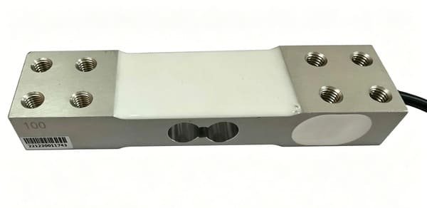
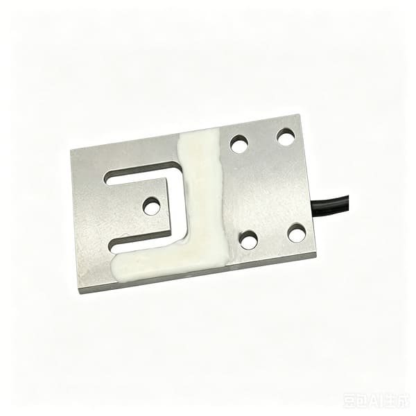
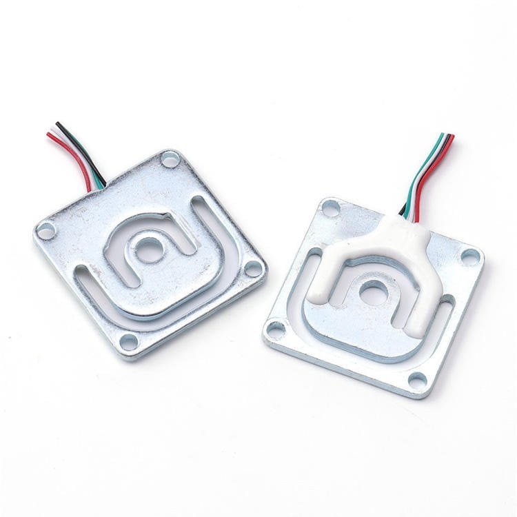
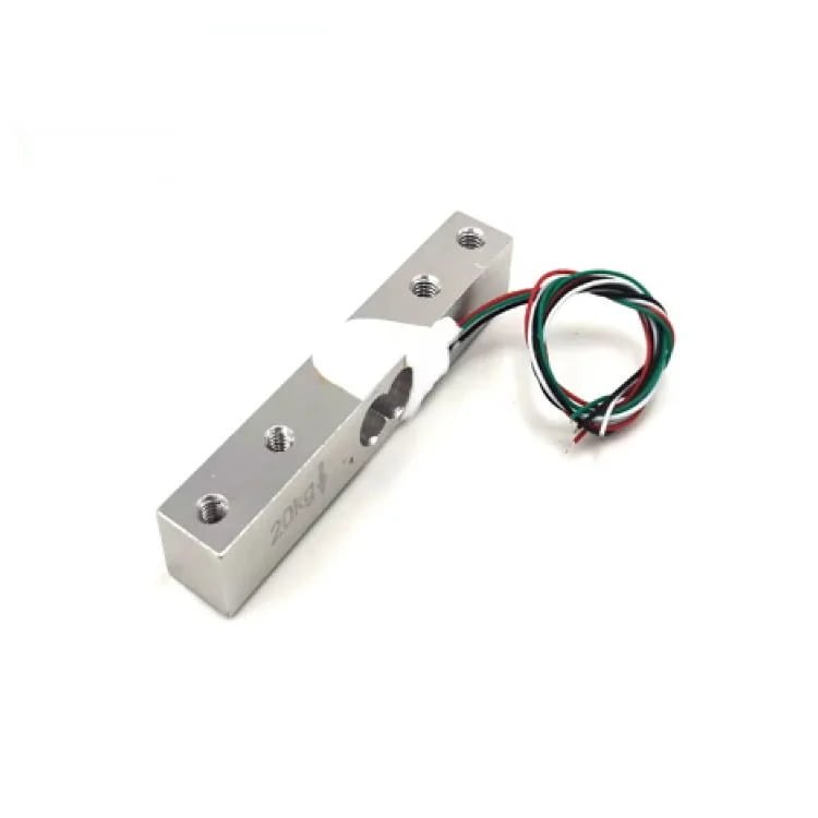
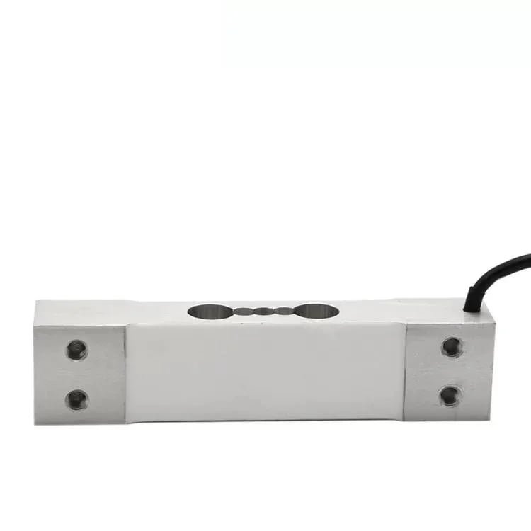
One note on that last point, because it applies to the whole list. I can compute the bridge current for WST1101 (1090 Ω, so about 4.6 mA at 5 V) and for WST201 (406 Ω, about 12.3 mA at 5 V) — a factor of 2.7× between two parts that look almost identical on a specification table, and a real consideration on a battery-powered machine. For WST101 and WST103 I cannot, because neither of my own product pages publishes bridge resistance. If you need a defensible power budget for a tray design, ask me for it and I will get it from the factory in writing rather than estimate it for you.
If you want more background before you choose, three of my other pages go deeper on the parts of this problem I have only sketched here: the working-principles guide covers strain gauge construction and why creep and zero drift behave the way they do; the reverse vending guide deals with machines that must decide what arrived, which is the same judgement problem as a tray; and the drone payload guide works through a weighing platform on a vehicle that is far more violent than yours. If your tray is on a street-side machine instead of a dining-room one, the smart bin notes cover the public-interaction overload cases in more detail, and if the machine is portable and gets recalibrated on site, the refrigerant scale selection guide is the closest analogue to a tray that lives on a trolley.
Market figures in this article are drawn from the Worldwide Food Delivery Robots Market study and the restaurant robots market analysis; the Machinery Regulation that the table in section 13 refers to is set out by the European Commission’s machinery pages. Sources differ on market size; the direction is consistent.
With those four I will come back with a capacity, an overload check, a threshold and a working point in one reply — usually inside twelve hours. I make the sensing chain: cells, force sensors, junction boxes and indicators. The robot, the mount and the firmware are yours, and I will tell you plainly where that line is.
Load cells, force sensors, junction boxes and weighing indicators